Table of Contents
Advertisement
Quick Links
Advertisement
Table of Contents

Subscribe to Our Youtube Channel
Related Manuals for HiBoost F27-5S


Summary of Contents for HiBoost F27-5S
- Page 1 User' s M anual F27-5S MADE IN HUAPTEC...
-
Page 2: Table Of Contents
Table of Contents Table of Contents ....................2 Operation ......................3 Package Contents .................... 3 Key Features ..................... 5 Key Components ....................5 LCD Features ....................6 Manual Gain Control Operation ..............8 Manual Gain Control (MGC) ................9 System Installation ................... 9 Before You Install .................. -
Page 3: Operation
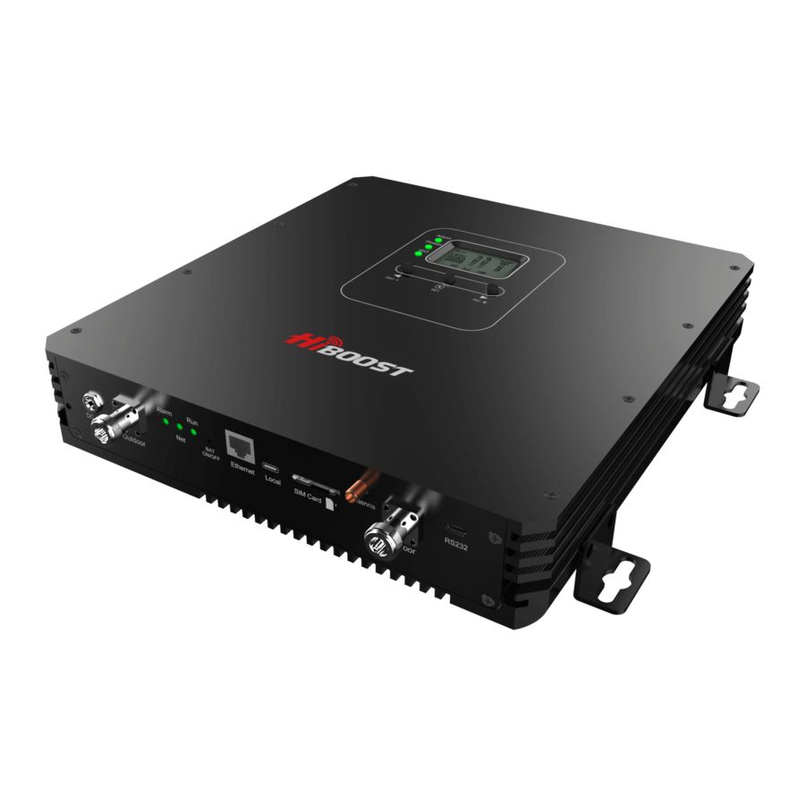
This manual covers operation, installation and troubleshooting procedures for the bi-directional amplifier Model: F27-5S. The F27-5S amplifier is designed to help wireless device users amplify weak signals of all the major carriers in the 2G, 3G and 4G bands. This bi-directional... - Page 4 Multiple Antenna Installation Sample 1.Outdoor Antenna 2. Booster 3.Indoor Panel Antenna Coupler 5. Splitter 6. Omni Ceiling Antenna Optional Accessories Recommended RF Cables Wide Band Yagi Antenna Outdoor Panel Antenna Outdoor Ceiling Mount Dome Antenna Indoor Panel Antenna Omni Ceiling Antenna Whip Antenna Lightning Protector Directional Coupler...
-
Page 5: Key Features
Cavity Splitter (2,3,4 way) Wilkinson Splitter (2,3,4 way) Key Features • Self-adaptive Smart Level Control (ALC): Enables convenient ‘plug and play’ installation and optimum coverage in complex and dynamically changing RF signal environments. • ISO: Smart isolation gain processing to avoid self-oscillation between antennas and avoid interference to the carrier network. -
Page 6: Lcd Features
LCD Features After the booster is powered on, uplink (UL) and downlink(DL) gain and DL output power are displayed. “Band”– Shows the working frequency. Below is a list of the frequencies displayed corresponding to the Band display shown on the screen. Frequency Band display 700MHz Lower A/B/C blocks... - Page 7 “Power dBm”– Power Indication. The displayed value shows real-time downlink power that the amplifier is delivering to the indoor antenna port. When the amplifier DL output power is lower than -10dBm, the value will display ”---”. “ISO” – Isolation Alarm Indication. When the system does not have enough isolation between the outdoor and indoor antennas, the “ISO”...
-
Page 8: Manual Gain Control Operation
Manual Gain Control Operation There are 4 operation modes relative to the control buttons: a long press for more than 3 seconds on the “SET” button, short press on the “SET” button, short press on “DEC-” button and short press on “INC+” button. When the LCD is in the fixed display mode, press the “SET”... -
Page 9: Manual Gain Control (Mgc)
Manual Gain Control (MGC) Since the booster has a very good self-adaptive smart automatic level control (ALC) and isolation gain processing (ISO) , most of the time manual adjustments are not required to achieve good coverage. However, in some cases where the ALC or ISO is working at a very high rate to adjust the gain and the Alarm or ISO LED is flashing more than once a second a manual adjustment might be desired. -
Page 10: Installation Overview
Installation Overview This amplifier has an LCD display and smart self-adaptive Automatic Level Control (ALC) and Isolation gain processing (ISO) system. The LCD displays real time working status and the ALC and ISO can automatically calculate and adjust the booster gain to obtain its optimum performance. So it is very easy to install. General installation steps: 1. - Page 11 • LCD Display Method Connect the outdoor antenna to the booster’s outdoor port. Fix the outdoor antenna on the roof of the building and point it to the nearest cell tower. Then have a look at gain and output power value displayed on the amplifier’s LCD. The outdoor antenna receives the strongest signal when the booster’s downlink output power reaches its highest level in each band.
- Page 12 Note: Please try to receive a signal from cell towers that are not overloaded with multiple users. This can be estimated by the population density in the area served by the tower. For example, it is recommended to avoid cell towers near supermarkets, shopping malls, stadiums or any other public places visited by many people regularly.
-
Page 13: Installation Of Indoor Antenna
Note: Wrap waterproof tape around the connectors between outdoor antenna and feeder line to avoid moisture ingress. Installation of Indoor Antenna Select indoor panel antenna or omni-ceiling antenna as an indoor antenna according to your needs to provide indoor coverage. Install the indoor panel antenna as shown on the graph below. -
Page 14: Install The Signal Booster
Install the signal booster 1. Select an indoor location near a power outlet on a wall. Please use a surge protector rated at a minimum of 1000 Joules between the amplifier’s power adaptor and the AC power outlet on the wall. 2. - Page 15 Check the downlink output power displayed by the LCD. It may vary dynamically at times between 1-3 dB which is normal due to outdoor signal conditions. It would be optimum that the output power reaches its maximum rated levels for the largest coverage; but you can always leave it set at lower levels if the coverage is adequate.
- Page 16 • Reduce the booster’s downlink gain with the manual gain control buttons. Keep the uplink gain value and downlink gain values the same then restart the booster. • If the indoor antennas are connected through a splitter network locate the antenna that is causing the ISO alarm by disconnecting each indoor antenna one at a time and insert an inline attenuator to reduce the signal power going to that particular antenna.
- Page 17 More about "ALC" indication: ALC indicates the strength of received signal level from the tower. Flashing ALC means that the booster is receiving a signal larger than required to drive the output to full power Status Meaning Solution Methods Check coverage, leave it as is if it’s good;...
- Page 18 More about LCD indication: Status Meaning Solution Methods Check coverage, leave it as it is if it’s good; take the actions below to increase received signal level if coverage is not good. Adjust the outdoor antenna “---” Downlink power Output power is status lower than - 10dBm direction or location to get a...
- Page 19 Status Meaning Solution methods No loop back or no Green NO action is needed self-oscillation Slow Slight loop back or NO action is needed Flashing self-oscillation Green Not working properly. Check coverage. Leave it as is if Deep loop back or Quick Flashing it’s good.
- Page 20 Alarm LED: Indicates the strength of received signal from the tower. Flashing Alarm means that the booster is receiving a strong signal in one or more of the bands. Alarm LED shall remain "Green" or "Slow Flashing Green". Slow flashing green indicates that everything is working well and the booster is working at nearly the optimum output power to achieve the best possible coverage.
-
Page 21: Trouble Shooting
1)If the signals in most areas have not been improved, please check below: • The weak downlink signal leads to the low output signal level. Change the direction of outdoor antenna or its installation position or replace the outdoor antenna with a higher gain antenna to increase the received signal level. -
Page 22: Specifications
Returned Material Authorization (RMA) number supplied by HiBoost. HiBoost will supply two options, repair or replace. HiBoost will cover the cost of delivery for the consumers located within the continental U.S. -
Page 23: Fcc Rf Exposure Statement
FCC RF Exposure Statement This equipment complies with FCC radiation exposure limits set forth for an uncontrolled environment. This equipment should be installed and operated with minimum distance 30cm between the radiator & your body. This transmitter must not be co-located or operating in conjunction with any other antenna or transmitter. -
Page 24: Warnings
Warnings Users of this product are cautioned to comply with following: Booster should be installed with good grounding and lightning protection. The power supply AC input voltage shall not exceed 240 VAC. Any maintenance operation shall be carried out only after cutting off power in advance.
Need help?
Do you have a question about the F27-5S and is the answer not in the manual?
Questions and answers