ABB Endura AZ20 series Maintenance Manual
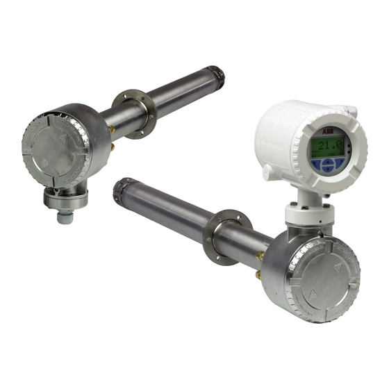
Probe combustion oxygen monitor
Hide thumbs
Also See for Endura AZ20 series:
- User manual (40 pages) ,
- Manual (16 pages) ,
- Instruction (8 pages)

Related Manuals for ABB Endura AZ20 series


Summary of Contents for ABB Endura AZ20 series
- Page 1 Maintenance Guide IM/AZ20M–EN Rev. B Endura AZ20 series probe Combustion oxygen monitor...
- Page 2 We are an established world force in the design and manufacture of measurement products for industrial process control, flow measurement, gas and liquid analysis and environmental applications. As a part of ABB, a world leader in process automation technology, we offer customers application expertise, service and support worldwide.
-
Page 3: Table Of Contents
Combustion Oxygen Monitor Endura AZ20 Series Probe Contents Contents 1 Safety ................3 5 Dismantling and Reassembly – Probe ......13 Health & Safety ............3 Before Removing / Replacing the Probe ....13 Symbols – CEI / IEC 61010-1:2001-2 ...... 3 Before Dismantling a Probe ........ - Page 4 Combustion Oxygen Monitor Endura AZ20 Series Probe Contents 7 Illustrated Parts List – Probe ........42 Cell Assembly ............43 Diffuser Flame Arrestor ...........43 C-ring Kit ..............43 AutoCal Assembly ..........43 7.4.1 AutoCal Upgrade Assembly ......43 7.4.2 AutoCal Refurbishment Kit ......43 AZ20 and AZ20/ZFG2 End Cap Replacement Kit ...43 Heater Assembly ...........44...
-
Page 5: Safety
Combustion Oxygen Monitor Endura AZ20 Series Probe 1 Safety 1 Safety Information in this manual is intended only to assist our This symbol, when noted on a product enclosure or customers in the efficient operation of our equipment. Use of... -
Page 6: Product Recycling Information
To ensure the protection provided by this equipment is not ABB is committed to ensuring that the risk of impaired, do not use or install this equipment in any manner any environmental damage or pollution caused other than that specified in this manual. -
Page 7: Safety Recommendations
Combustion Oxygen Monitor Endura AZ20 Series Probe 2 Introduction 1.9 Safety Recommendations 2 Introduction For safe operation, it is imperative that these service instructions This Maintenance Guide provides dismantling and reassembly be read before use and that the safety recommendations procedures for AZ20 probes (both integral and remote versions) mentioned herein be scrupulously respected. -
Page 8: Troubleshooting - Quick Checks
Combustion Oxygen Monitor Endura AZ20 Series Probe 3 Troubleshooting – Quick Checks 3 Troubleshooting – Quick Checks Troubleshooting diagnostics are displayed on the transmitter – Referring to Fig.3.2: refer to the transmitter User Guide (IM/AZ20E–EN). Where a 3. At the probe, unscrew and remove the end cap... -
Page 9: Checking The Heater Resistance
Combustion Oxygen Monitor Endura AZ20 Series Probe 3 Troubleshooting – Quick Checks 3.3 Checking the Heater Resistance 3.4 Checking the Thermocouple / Electrode Assembly Resistance Referring to Fig. 3.3: Referring to Fig. 3.4: 1. At the 9-way terminal block , measure the resistance 1. -
Page 10: Checking The Acjc Resistance (Az20 Probe Only)
Combustion Oxygen Monitor Endura AZ20 Series Probe 3 Troubleshooting – Quick Checks 3.5 Checking the Cell Isolation 3.6 Checking the ACJC Resistance (AZ20 Probe Only) Referring to Fig. 3.5: Referring to Fig. 3.6: 1. At the 9-way terminal block , check the resistance from 1. -
Page 11: Troubleshooting - Functional Checks
Combustion Oxygen Monitor Endura AZ20 Series Probe 4 Troubleshooting – Functional Checks 4 Troubleshooting – Functional Checks 4.1 Equipment Required Warning. Due to the presence of high voltage heater AZ20 User Guides (transmitter User Guide IM/AZ20E–EN, terminals / wires (85 to 265 V) in the probe head the probe’s and the probe User Guide IM/AZ20P–EN) -
Page 12: Checking Cell Output Voltage
Combustion Oxygen Monitor Endura AZ20 Series Probe 4 Troubleshooting – Functional Checks Ambient Temp. Millivolts Ambient Temp. Millivolts Ambient Temp. Millivolts Ambient Temp. Millivolts °C (°F) °C (°F) °C (°F) °C (°F) 50 (122) 27.106 24 (75.2) 28.168 37 (98.6) 27.639... -
Page 13: Cell Function Check
Combustion Oxygen Monitor Endura AZ20 Series Probe 4 Troubleshooting – Functional Checks 4.3.1 Cell Function Check 4.3.2 Detailed Cell Accuracy Check Note. This check uses 1 test gas. Note. This detailed check uses 2 test gases – checking the isolated cell output voltage using 2 test gases provides the most accurate result. -
Page 14: System Functional Check
Combustion Oxygen Monitor Endura AZ20 Series Probe 4 Troubleshooting – Functional Checks The following examples show calculations for process 4.4 System Functional Check temperatures <700 °C and >700 °C: This section checks the AZ20 probe and associated transmitter for system functionality and accuracy. -
Page 15: Dismantling And Reassembly - Probe
Combustion Oxygen Monitor Endura AZ20 Series Probe 5 Dismantling and Reassembly – Probe 5 Dismantling and Reassembly – Probe 5.1 Before Removing / Replacing the Probe 5.3 Preparation following equipment working conditions recommended to ensure the probe is maintained in a suitable Warning. -
Page 16: Removing / Refitting An Integral Probe
Combustion Oxygen Monitor Endura AZ20 Series Probe 5 Dismantling and Reassembly – Probe 5.4 Removing / Refitting an Integral Probe 5.5 Removing / Refitting a Remote Probe Referring to Fig. 5.1: 1. Isolate the remote transmitter from mains power supplies and label the isolator to prevent power being reconnected 1. -
Page 17: Replacing The End Cap And Seal
Combustion Oxygen Monitor Endura AZ20 Series Probe 5 Dismantling and Reassembly – Probe 5.6 Replacing the End Cap and Seal Warning. If the end cap is replaced with the probe in situ, ensure the system it is used in has been shut down and isolated to prevent the risk of electrical shocks. -
Page 18: Replacing The Diffuser Flame Arrestor And / Or Cell
Combustion Oxygen Monitor Endura AZ20 Series Probe 5 Dismantling and Reassembly – Probe 5.7 Replacing the Diffuser Flame Arrestor and / or Cell 5. Carefully withdraw the diffuser flame arrestor while supporting the cell . If necessary, use a solvent, for example lighter fluid (petroleum ether) or alcohol (surgical Warning. - Page 19 Combustion Oxygen Monitor Endura AZ20 Series Probe 5 Dismantling and Reassembly – Probe Red (Cell +) Green (TC +) White (TC –) AZ20 Probe with AutoCal AZ20 (Non- AutoCal) or AZ20/ZFG2 Replacement Probe Fig. 5.4 Removing the Cell and C-ring...
-
Page 20: Fitting A New C-Ring And Cell
Combustion Oxygen Monitor Endura AZ20 Series Probe 5 Dismantling and Reassembly – Probe 5.7.3 Fitting a New C-ring and Cell 5.7.4 Fitting the Diffuser Flame Arrestor Referring to Fig. 5.5: Referring to Fig. 5.6: 1. Transfer alteration details onto 1. Locate the diffuser flame arrestor... - Page 21 Combustion Oxygen Monitor Endura AZ20 Series Probe 5 Dismantling and Reassembly – Probe Red (Cell +) Green (TC +) 1000 White (TC –) AZ20 Probe with AutoCal AZ20 (Non- AutoCal) or AZ20/ZFG2 Replacement Probe Fig. 5.6 Fitting a New C-ring and Cell...
-
Page 22: Replacing The Thermocouple / Electrode Assembly
Combustion Oxygen Monitor Endura AZ20 Series Probe 5 Dismantling and Reassembly – Probe 5.8 Replacing the Thermocouple / 5.8.1 Removing the Thermocouple / Electrode Assembly Electrode Assembly Referring to Fig. 5.7: 1. At the probe head, disconnect the red (Cell +), green (TC+) Note. - Page 23 Combustion Oxygen Monitor Endura AZ20 Series Probe 5 Dismantling and Reassembly – Probe Red (Cell +) Green (TC +) 1000 White (TC –) Fig. 5.7 Removing the Thermocouple / Electrode Assembly IM/AZ20M–EN Rev. B...
-
Page 24: Fitting A New Thermocouple / Electrode Assembly
Combustion Oxygen Monitor Endura AZ20 Series Probe 5 Dismantling and Reassembly – Probe 5.8.2 Fitting a New Thermocouple / Electrode Assembly Referring to Fig. 5.8: 1. Remove the existing spring locator from the old assembly. 2. Lay the new assembly... - Page 25 Combustion Oxygen Monitor Endura AZ20 Series Probe 5 Dismantling and Reassembly – Probe Referring to Fig. 5.9: 8. Slide the 2 electrode contact springs and the new spring locator over the sleeved wires and slide them along until the springs butt up to the insulator.
-
Page 26: Replacing The Heater Assembly
Combustion Oxygen Monitor Endura AZ20 Series Probe 5 Dismantling and Reassembly – Probe Heater 5.9 Replacing the Heater Assembly 5.9.1 Removing the Assembly Referring to Fig. 5.10: Note. Check all items for damage as they are removed. 1. Disconnect the internal earth connection Keep items for reuse in a clean safe place. - Page 27 Combustion Oxygen Monitor Endura AZ20 Series Probe 5 Dismantling and Reassembly – Probe Test Gas Tube to Sensor Location Test Gas Tube to Sensor Location on Probes Fitted with AutoCal on Non-AutoCal AZ20 and AZ20/ZFG2 Probes Fig. 5.10 Removing the Heater Assembly...
-
Page 28: Dismantling The Heater Assembly
Combustion Oxygen Monitor Endura AZ20 Series Probe 5 Dismantling and Reassembly – Probe 5.9.2 Dismantling the Heater Assembly Referring to Fig. 5.11: 1. Remove the red tube and pull the sleeved heater wires 4. Remove each insulator by sliding it over the heater through the internal structure mounting plate / end wires. -
Page 29: Assembling The New Heater Assembly
Combustion Oxygen Monitor Endura AZ20 Series Probe 5 Dismantling and Reassembly – Probe 5.9.3 Assembling the New Heater Assembly Referring to Fig. 5.12: 1. Join the heater assembly end plate and the inner Secure each insulator by folding alternate insulator... -
Page 30: Fitting The New Heater Assembly
Combustion Oxygen Monitor Endura AZ20 Series Probe 5 Dismantling and Reassembly – Probe 5.9.4 Fitting the New Heater Assembly Referring to Fig. 5.13: 1. Ensure the test gas tube is clean and free of 3. Ensure the inner assembly is supported along its entire blockages. - Page 31 Combustion Oxygen Monitor Endura AZ20 Series Probe 5 Dismantling and Reassembly – Probe Referring to Fig. 5.14: AZ20/ZFG2 Replacement Probes only – disconnect the internal Reference Air tube (connected to the internal 5. Fit and tighten the 3 internal structure mounting plate M4 conduit) from the connection on the probe body.
-
Page 32: Fitting Autocal As An Upgrade
Combustion Oxygen Monitor Endura AZ20 Series Probe 5 Dismantling and Reassembly – Probe 5.10 Fitting AutoCal as an Upgrade Note. This procedure upgrades a standard AZ20 probe to provide AutoCal capability (not applicable to AZ20/ZFG2 replacement probes). Refer to Appendix B.3 to B.5, pages 49 to 50 for further information. -
Page 33: Fitting An Autocal Assembly
Combustion Oxygen Monitor Endura AZ20 Series Probe 5 Dismantling and Reassembly – Probe 5.10.2 Fitting an AutoCal Assembly Note. Refer to Appendix B.4, page 50 for AutoCal manifold block orientation details. Referring to Fig. 5.16: 1. Locate the AutoCal manifold... - Page 34 Combustion Oxygen Monitor Endura AZ20 Series Probe 5 Dismantling and Reassembly – Probe Referring to Fig. 5.17: 8. Withdraw the thermocouple / electrode assembly out of the inner assembly by approximately 50 to 70 mm (2 to 2.8 in.). 9. Carefully slide the inner assembly into position.
- Page 35 Combustion Oxygen Monitor Endura AZ20 Series Probe 5 Dismantling and Reassembly – Probe Referring to Fig. 5.18: 16. Fit test gas to sensor tube and reference air tube 17. Fit test gas 1 and 2 tubes 18. Push the 2 terminal plugs...
-
Page 36: Replacing / Fitting Restrictors
Combustion Oxygen Monitor Endura AZ20 Series Probe 5 Dismantling and Reassembly – Probe 5.11 Replacing / Fitting Restrictors 10. Mark the Commissioning label on the probe to show that restrictors are fitted. Note. The restrictors have extremely small orifices so 11. -
Page 37: Replacing The Pt1000 Temperature Sensor
Combustion Oxygen Monitor Endura AZ20 Series Probe 5 Dismantling and Reassembly – Probe 5.12 Replacing the PT1000 Temperature Sensor Before fitting the PT1000 sensor: Ensure a PT1000 sensor is available – refer to Section 7.8, page 44. Remove the probe from its mounting as detailed in Section 5.4, page 14 (integral probe) or Section 5.5, page... -
Page 38: Dismantling And Reassembly - Transmitter
Combustion Oxygen Monitor Endura AZ20 Series Probe 6 Dismantling and Reassembly – Transmitter 6 Dismantling and Reassembly – Transmitter Warning. Before dismantling the transmitter, clean the outer surfaces of the transmitter thoroughly. Handle internal components carefully, keep them clean and ensure mating surfaces are not damaged during maintenance procedures. -
Page 39: Replacing The Integral Transmitter Cartridge
Combustion Oxygen Monitor Endura AZ20 Series Probe 6 Dismantling and Reassembly – Transmitter 6.1.2 Replacing the Integral Transmitter Cartridge Warning. Isolate the transmitter from power supplies before removing the cover and label the isolator to prevent accidental switch on. 1. Ensure a replacement cartridge of the correct type is available –... -
Page 40: Replacing The Integral Transmitter Backplane
Combustion Oxygen Monitor Endura AZ20 Series Probe 6 Dismantling and Reassembly – Transmitter 6.2 Replacing the Integral Transmitter Backplane 6.2.1 Removing the Backplane 6.2.2 Fitting a New Backplane Referring to Fig. 6.4: Warning. Isolate the transmitter from power supplies before 1. -
Page 41: Replacing The Remote Transmitter Backplane
Combustion Oxygen Monitor Endura AZ20 Series Probe 6 Dismantling and Reassembly – Transmitter 6.3 Replacing the Remote Transmitter Backplane 6.3.1 Removing the Backplane 6.3.2 Fitting a New Backplane Referring to Fig. 6.6: Warning. Isolate the transmitter from power supplies before 1. -
Page 42: Probe Cable Connections To Remote Transmitter
Combustion Oxygen Monitor Endura AZ20 Series Probe 6 Dismantling and Reassembly – Transmitter 6.3.3 Probe Cable Connections to Remote Transmitter Referring to Fig. 6.7: 1. Feed the probe cable through cable gland and tighten the gland. 2. Make probe cable connections at the probe as detailed in Appendix B, page 48. -
Page 43: Power Supply And Output Connections To Remote Transmitter
Combustion Oxygen Monitor Endura AZ20 Series Probe 6 Dismantling and Reassembly – Transmitter 6.3.4 Power Supply and Output Connections to Remote Transmitter To make power supply and output connections: Warning. 1. Feed the incoming AC power supply cable through cable ... -
Page 44: Illustrated Parts List – Probe
Combustion Oxygen Monitor Endura AZ20 Series Probe 7 Illustrated Parts List – Probe 7 Illustrated Parts List – Probe Item Description Kit Components Replacement Procedure Cell assembly Table 7.1, page 43 Refer to Section 5.7, page 16 Diffuser flame arrestor Table 7.2, page 43... -
Page 45: Cell Assembly
Combustion Oxygen Monitor Endura AZ20 Series Probe 7 Illustrated Parts List – Probe 7.1 Cell Assembly BSP Version Item Quantity Cell Item Quantity M4 x 50 cap head screws AutoCal manifold block assembly M4 nuts AutoCal connection loom C-ring 6-Way terminal block with plug... -
Page 46: Thermocouple / Electrode Assembly
Combustion Oxygen Monitor Endura AZ20 Series Probe 7 Illustrated Parts List – Probe 7.6 Heater Assembly 7.7 Thermocouple / Electrode Assembly Note. The heater and heater support column is supplied as Note. Kits for probe lengths 0.5 to 2.0 m (1.64 to 6.56 ft.) an assembled unit for all kits. -
Page 47: Illustrated Parts List - Transmitter
Combustion Oxygen Monitor Endura AZ20 Series Probe 8 Illustrated Parts List – Transmitter 8 Illustrated Parts List – Transmitter Item Description Kit Components Replacement Procedure Cartridge Table 8.1 Refer to Section 6.1, page 36 Integral (Type 3) probe backplane Table 8.2 Refer to Section 6.2, page 38... -
Page 48: Appendix A - Connection Diagrams
Combustion Oxygen Monitor Endura AZ20 Series Probe Appendix A – Connection Diagrams Appendix A – Connection Diagrams A.1 AZ20 Integral Probe Fig. A.1 AZ20 Integral Probe – Connection Diagram IM/AZ20M–EN Rev. B... -
Page 49: Az20 Remote Probe
Combustion Oxygen Monitor Endura AZ20 Series Probe Appendix A – Connection Diagrams A.2 AZ20 Remote Probe Fig. A.2 AZ20 Remote Probe – Connection Diagram IM/AZ20M–EN Rev. B... -
Page 50: Appendix B - Probe Electrical Connections
Combustion Oxygen Monitor Endura AZ20 Series Probe Appendix B – Probe Electrical Connections Appendix B – Probe Electrical Connections B.1 AZ20 Probe Transmitter Cable Connections Transmitter terminal Note. Non-AutoCal probes are not fitted with the 6-way plug connected AutoCal terminal block or pressure switch / solenoid valve to transmitter option. -
Page 51: Autocal Connections At Az20 Probe
Combustion Oxygen Monitor Endura AZ20 Series Probe Appendix B – Probe Electrical Connections B.3 AutoCal Connections at AZ20 Probe Terminal / Cable Tag ID AutoCal Connection Color Pressure Switch White / Yellow Gas 2 White / Black PS COM Pressure Switch Common... -
Page 52: Autocal Pressure Switch Connections
Combustion Oxygen Monitor Endura AZ20 Series Probe Appendix B – Probe Electrical Connections B.4 AutoCal Pressure Switch Connections B.5 AutoCal Solenoid Valve Terminal Connections Notes. Notes. Refer to Table B.3, page 49 for pressure switch Refer to Table B.3, page 49 for solenoid valve terminal terminal connections. - Page 53 Combustion Oxygen Monitor Endura AZ20 Series Probe Notes Notes IM/AZ20M–EN Rev. B...
- Page 54 Combustion Oxygen Monitor Endura AZ20 Series Probe Notes IM/AZ20M–EN Rev. B...
- Page 55 Repair Centre. — Metals and Minerals — Oil, Gas & Petrochemical — Pulp and Paper ABB Limited Drives and Motors Tel: +44 (0)1453 826661 — AC and DC Drives, AC and DC Machines, AC Motors to Fax: +44 (0)1453 829671 —...
- Page 56 With regard to purchase orders, the agreed For more product information visit: particulars shall prevail. ABB does not accept any www.abb.com responsibility whatsoever for potential errors or possible lack of information in this document.
Need help?
Do you have a question about the Endura AZ20 series and is the answer not in the manual?
Questions and answers