Table of Contents
Advertisement
Quick Links
Advertisement
Table of Contents

Related Manuals for ABB 9438


Summary of Contents for ABB 9438
- Page 1 User Guide Low and High Level IM/9438_6 Dissolved Oxygen Monitor 9438...
-
Page 2: Electrical Safety
Cert. No. Q 05907 As a part of ABB, a world leader in process automation technology, we offer customers application expertise, service and support worldwide. EN 29001 (ISO 9001) We are committed to teamwork, high quality manufacturing, advanced technology and unrivalled service and support. -
Page 3: Table Of Contents
Flowcell Solenoid Valve Connections ....11 11.1 Strategic Spares ..........32 SETTING UP ............... 12 APPENDIX A – 9438 080 24 V DC Fitting the Dissolved Oxygen Sensor ....12 POWER SUPPLY UNIT (OPTIONAL) ......34 Connecting the Flowcell ........13 Description ............ -
Page 4: Introduction
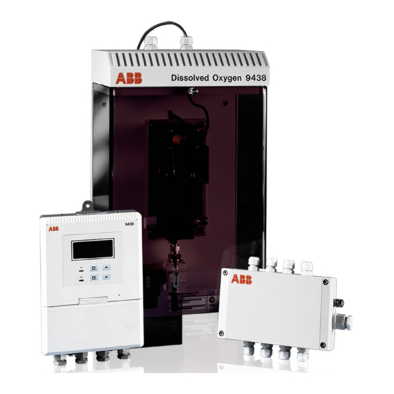
1 INTRODUCTION This manual describes how to install and operate the 9438 Low Level Dissolved Oxygen Monitoring system. Fig. 1.1 shows the Model 9438 Wall-Mounted Transmitter main elements of the system. Mechanical and electrical installation details of the optional power supply unit are in Appendix A. -
Page 5: Mechanical Installation
2 MECHANICAL INSTALLATION 2.1 Siting Requirements 2.1.2 Dissolved Oxygen Flowcell – Fig 2.7 Allow sufficient clearance (200 mm all around) for easy removal 2.1.1 Instruments – Fig. 2.1 of the flowcell assembly for maintenance when not installed in the optional enclosure – see Section 2.3.1 for overall dimensions of units. -
Page 6: Panel-Mounted Instrument
…2 MECHANICAL INSTALLATION …2.2.1 Wall-mounted Instrument – Fig 2.4 2.2.2 Panel-mounted Instrument – Figs 2.5 and 2.6 Dimensions in mm (in) Position ‘U’ bolts on pipe Position plates over ‘U’ bolts 191 (7.52) 96 (3.78) 12 (0.47) (3.78) +0.8 +0.03 (3.62 –0 –0... -
Page 7: Installing The Dissolved Oxygen Flowcell
M8 fastener in rubber tubing fixing holes and suitable four positions screws/bolts. Sample drain during Sample Dissolved Oxygen 9438 automatic calibration Outlet Drain – see Note Note. Drain tubes must be straight and vertical to allow the sample to flow freely. -
Page 8: Electrical Connections
3 ELECTRICAL CONNECTIONS Warning. • Before making any connections, ensure that the power supply, any high voltage-operated control circuits and high common mode voltage are switched off. • Although certain instruments are fitted with internal fuse protection, a suitably rated external protection device, e.g. fuse or miniature circuit breaker (m.c.b.), must also be fitted by the installer. -
Page 9: Connections, General
3 ELECTRICAL CONNECTIONS… 3.2 Connections, General Information. • Earthing (grounding) – stud terminals are fitted to the transmitter case for bus-bar earth (ground) connection – see Fig. 3.1 or 3.2. • Cable lengths – The cable length between the flowcell and the electronics unit is provided as ordered, and suitably terminated at both ends. -
Page 10: System Wiring Schematic
9438 Transmitter supplied 24 V DC supply is shown in Fig. 3.4. Relay 2 C NO If the 9438 080 power supply unit is employed, refer to Appendix A for wiring details. Solenoid Valve Customer 24 V DC supply –ve... -
Page 11: Panel-Mounted Instrument Connections
3 ELECTRICAL CONNECTIONS… 3.4 Panel-mounted Instrument Connections – Fig. 3.6 Note. Refer to Fig. 3.2 for Access to Terminals. Caution. Slacken terminal screws fully before making connections. Earth Stud Retransmission Retrans 2 Output RS422/RS485 Rx– – Output (if fitted) Serial Interface (if fitted) Tx–... -
Page 12: Selecting The Mains Voltage
…3 ELECTRICAL CONNECTIONS 3.5 Selecting the Mains Voltage 3.5.1 Wall-mounted Instrument – Fig. 3.7 3.5.2 Panel-mounted Instrument – Fig. 3.8 Note. Some versions are fitted with a switch in place of links. The Slide instrument applied voltage should be as out of case indicated on the switch, when positioned. -
Page 13: Flowcell Solenoid Valve Connections
Nominal diameter = 5.4 mm (minimum 5.0 mm) Note. Use 2 core cable with 9438 080 PSU (ABB part number 0233 731). Use 3 core cable with customer supplied 24 V DC supply. +24 V DC via N/O of relay... -
Page 14: Setting Up
4 SETTING UP 4.1 Fitting the Dissolved Oxygen Sensor – Fig. 4.1 Caution. • Only install the oxygen sensor immediately prior to use, otherwise leave it stored in its protective container. The sensor has a limited shelf life and should NOT be stored longer than about 6 months. -
Page 15: Connecting The Flowcell
4 SETTING UP 4.2 Connecting the Flowcell – Fig. 4.2 Push the sensor connector on firmly and tighten ONE TURN clockwise. Line up the red spots and push the plug on firmly until the locking ring engages. Note. • The plug is a latching type to prevent it's accidental removal. -
Page 16: Controls And Displays
5 CONTROLS AND DISPLAYS 5.1 Displays – Fig. 5.1 The display comprises a 5-digit, 7-segment digital upper display Advance to line and a 16-character dot-matrix lower display line. The upper next page display line shows numerical values of dissolved oxygen Page 1 Page 2 concentration, temperature, alarm set points or programmable... -
Page 17: Start Up And Operation
6 START UP AND OPERATION... -
Page 18: Instrument Start-Up
…6 START UP AND OPERATION 6.1 Instrument Start-up – Fig. 6.1 Ensure all electrical connections have been made and switch on the power supply. If the instrument is being commissioned for the first time, calibration and programming of parameters is required. The overall operating and programming chart is shown in Fig. -
Page 19: Calibration Page
6 START UP AND OPERATION 6.2.2 Calibration Page Calibration involves standardizing the instrument and the sensor by exposing the sensor to air. During a calibration, retransmission and alarm outputs are automatically held to prevent inadvertent operation of ancillary equipment. Press to advance to next parameter –... -
Page 20: Programming And Electrical Calibration
7 PROGRAMMING AND ELECTRICAL CALIBRATION 7.1 Access to Secure Parameters A 5-digit security code is used to prevent tampering with the secure parameters. Security Code 0 0 0 0 0 Enter the required code number between 00000 and 19999 to gain access to the secure parameters. -
Page 21: Set Up Alarm Page
7 PROGRAMMING AND ELECTRICAL CALIBRATION… 7.4 Set Up Alarm Page Press to advance to next parameter – – – – – Press to advance to , Section 7.5. Set Up Retrans Page SET UP ALARM Alarm Type – – – – – Select the type of alarm required. - Page 22 …7 PROGRAMMING AND ELECTRICAL CALIBRATION …7.4 Set Up Alarm Page ...Continued from A1 Action High Set Point 1 5 0 . set point can be set to any value within the full measurement range, with the High units automatically changing. High Spt ug/kg The set point value is subject to hysteresis as detailed above.
-
Page 23: Set Up Retransmission Page
7 PROGRAMMING AND ELECTRICAL CALIBRATION… 7.5 Set Up Retransmission Page In this section the actual values denoted by 'xxxxx' are unimportant and are used to determine display reading stability when carrying out the electrical calibration procedure. Press to advance to next parameter –... - Page 24 Fail S.time See Appendix B. Set Up Retransmission 2 – see also Table 7.1. – – – – – Note. Available only on 9438 800 series instruments. SET UP RETRANS Retransmission 2 Output Range – – – – – The retransmission 2 output can be selected from three mA current ranges to ensure compatibility with the peripheral device connected.
- Page 25 7 PROGRAMMING AND ELECTRICAL CALIBRATION… …7.5 Set Up Retransmission Page Bi-linear Linear Enter Input % 1 0 0 . Set the percentage of the display span at which the breakpoint occurs: 1.0 to 100% in 0.1% increments. This is point A on Fig. 7.1. Enter Input Enter Output % 5 0 0 .
-
Page 26: Electrical Calibration
…7 PROGRAMMING AND ELECTRICAL CALIBRATION 7.6 Electrical Calibration Note. The instrument is calibrated by the company prior to despatch and an electrical calibration should be carried out only if the accuracy of the instrument is suspect and suitably calibrated test equipment is available. 7.6.1 Equipment Required a) Current source: 0 to +100 µA. -
Page 27: Factory Settings Page
7 PROGRAMMING AND ELECTRICAL CALIBRATION… 7.7 Factory Settings Page xxxxx When carrying out the electrical calibration procedure, the actual values denoted by are unimportant and are used only to determine display reading stability. Press to advance to next parameter – – – – – Press to return to , Section 6.2.1. - Page 28 …7 PROGRAMMING AND ELECTRICAL CALIBRATION …7.7 Factory Settings Page Adjust Retransmission Span – – – – – Set the milliammeter reading to 20.00 mA. Adjust RTX Span Note. Retransmission signal span is calibrated using 20.00 mA. The correct value transmitted depends on the range selected in the Set Up Outputs Page Adjust Retransmission Zero 2 –...
- Page 29 7 PROGRAMMING AND ELECTRICAL CALIBRATION Dissolved Oxygen Measurement – shown as % of Display Span Fig. 7.1 Bi-Linear Scaling 100% Dissolved Oxygen Measurement – shown as % of Display Span Fig. 7.2 Logarithmic Scaling (two decades example)
-
Page 30: Maintenance
8 MAINTENANCE 8.1 Introduction 3) Inspect the sensor. If the membrane is clean, refit the sensor as in 5) below. No routine maintenance is required for this instrument other than periodic calibration – see Section 6.2.2. However, if following a If deposits are visible on the membrane, remove by gently calibration the sensor output shows one flashing bar, the sensor wiping the membrane with a moist paper tissue;... -
Page 31: Simple Fault Finding
9 SIMPLE FAULT FINDING 9.1 Diagnostic Messages If erroneous or unexpected results are obtained the fault may be indicated by an error message. If Alarm A1 has been selected as a STATUS alarm, then the LED and relay operation can be seen in Table 9.1. The STATUS alarm operates as a FAILSAFE alarm (during an alarm condition the relay state is the same as the power-down state, i.e. -
Page 32: Low Sensor Efficiency/Slow Sensor Cal. Or No Response To D.o. Changes
…9 SIMPLE FAULT FINDING 9.2 Low Sensor Efficiency/Slow Sensor Cal. or no 9.3 Checking the Temperature Input Response to D.O. Changes Check that the instrument responds to a temperature input. Disconnect the PT1000 leads and connect a suitable resistance a) Check that the sample drains fully from flowcell. If the sample box directly to the transmitter inputs –... -
Page 33: Specification
10 SPECIFICATION System Power Requirements Measuring ranges System –1 Programmable within the ranges 0 to 20.0 µg kg and 0 to Power consumption, <21 VA 20 mg kg –1 Transmitter Scaling Power supply, 100 to 130 V or 200 to 260 V 50/60 Hz µg kg –1 , mg kg... -
Page 34: Spares
11.1 Strategic Spares 5-digit x 7-segment back-lit l.c.d. Part No. Description ..........Qty Information 16-character, single line, dot matrix, back-lit l.c.d. 9438 080 24V Power Supply Unit ........1 0234 037 Solenoid Valve assembly ......... 1 Insulation, contacts to earth 0216 574 Flow Gauge assembly ........ - Page 35 11 SPARES Note. Ensure that the correct O-rings are fitted in the appropriate positions as shown. Fit new O-rings when a new sensor is fitted. O-ring Replacement Seals Pack (9437016) comprising: End Cap 2 x large O-rings 2 x small O-rings 2 x nylon seals 2 x end caps* 1 x protective cover...
-
Page 36: Appendix A - 9438 080 24 V Dc Power Supply Unit (Optional)
APPENDIX A – 9438 080 24 V DC POWER SUPPLY UNIT (OPTIONAL) A.1 Description A.3 Accessing PSU Terminals – Fig. A.2 The 24 V DC switch mode power supply unit is capable of powering up to four separate 9438 dissolved oxygen system Slacken solenoids. -
Page 37: Psu Connections
APPENDIX A – 9438 080 24 V DC POWER SUPPLY UNIT (OPTIONAL) A.4 PSU Connections – Fig. A.3 To solenoid valve on flowcell assembly (maximum: 4 valves) Pre-wired to terminal block SWITCHED OUTPUT TO SOL VALVE 110/115 V AC SOL 4... -
Page 38: Appendix B - Calibration Diagnostics
APPENDIX B – CALIBRATION DIAGNOSTICS The transmitter can be configured to enable the current output signal to indicate certain calibration diagnostic information. If the option for diagnostics is selected within the Set Up Retransmission scrolls, then the current output will indicate when a calibration is taking place, and also will indicate if the sensor is giving Low Sensor Efficiency. - Page 39 – Manufacturing United Kingdom – Metals and Minerals – Oil, Gas & Petrochemical ABB Limited – Pulp and Paper Tel: +44 (0)1453 826661 Fax: +44 (0)1453 829671 Drives and Motors United States of America • AC and DC Drives, AC and DC Machines, AC motors to 1kV ABB Inc.
- Page 40 ABB has Sales & Customer Support The Company’s policy is one of continuous product improvement and the right is reserved to modify the expertise in over 100 countries worldwide information contained herein without notice. Printed in UK (05.05) www.abb.com © ABB 2005 ABB Limited ABB Inc.
Need help?
Do you have a question about the 9438 and is the answer not in the manual?
Questions and answers