
Subscribe to Our Youtube Channel
Related Manuals for FMT Swiss AG 23 829


Summary of Contents for FMT Swiss AG 23 829
-
Page 1: Operating Instructions
OPERATING INSTRUCTIONS AND SAFETY NOTES NUMERIxx oval gear meter 2 - 100 l/min Pulse meter IPG... - Page 2 Operating instructions - digital oval gear meter and pulse meter FMT Swiss AG This documentation is exclusively intended for the operating company and their staff. Without our written consent, the content of this documentation (textes, figures, drawings, charts, diagrams etc. ), must not be duplicated or distributed, neither in full or in part, utilized for the purpose of competition or passed on/made availabe to third parties.
-
Page 3: Table Of Contents
Operating instructions - digital oval gear meter and pulse meter Table of Contents Introduction ________________________________________________________________________4 Preface ____________________________________________________________________________4 Obligations of the personnel ___________________________________________________________4 Symbols in this manual _______________________________________________________________4 1.3.1 Structure of the warning notes _________________________________________________________4 1.3.2 Hazard warning symbols ______________________________________________________________5 1.3.3 General symbols _____________________________________________________________________5 Safety notes ________________________________________________________________________5 Authorized personnel_________________________________________________________________6... -
Page 4: Introduction
Please carefully read these operating instructions and observe in particular all safety notes! Our staff will be pleased to provide support if you have any questions about the product. Yours sincerely, FMT Swiss AG Obligations of the personnel Before they start to work, all persons who are entrusted with work with the oval gear meter, are obliged: –... -
Page 5: Hazard Warning Symbols
Operating instructions - digital oval gear meter and pulse meter NOTE Indicates further information or tips which facilitate work. 1.3.2 Hazard warning symbols Symbol Meaning General hazard symbol. The warning note marked in this way contains supplementary information on the type of hazard. This symbol warns of dangerous electrical voltages. -
Page 6: Authorized Personnel
Operating instructions - digital oval gear meter and pulse meter Authorized personnel Only qualified and authorized persons are allowed to operate and to work on the oval gear meter. Persons are qualified if they are, due to their training, experience, instruction and knowledge of the relevant standards, able to assess assigned tasks and to identify potentially hazardous situations. -
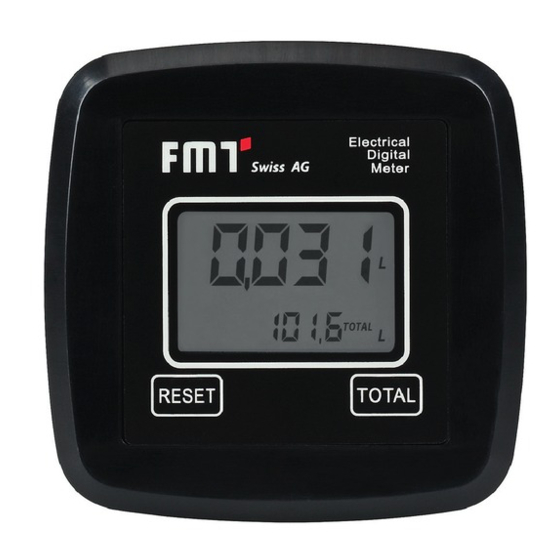
Page 7: Lcd Display
Operating instructions - digital oval gear meter and pulse meter LCD DISPLAY MEASURING CHAMBER RESET BUTTON TOTAL BUTTON The electronic components and LCD display sit at the top of the oval gear meter, well insulated against the wet measuring chamber. There is a cover to protect them against the working environment. 3.1.1 LCD display The meter‘s LCD display is equipped with two numeric registers and different types of display modes showing information to the user only when it is actually needed with the operation / function going on... -
Page 8: User Controls
Operating instructions - digital oval gear meter and pulse meter 5. Total volume multiplication factor (x10/x100) 6. Type of total volume display (TOTAL/RESET TOTAL) 7. Units for total volume; L=litres; GAL=gallons 8. Flow rate display 9. Display of measuring unit for partial volumes: QTS=quarters;... -
Page 9: Technical Data
Pulse meter Pulse meter Diesel Oval gear meter Oval gear meter 23 190 with display without display Diesel Diesel 23 829 23 820 Measuring system oval gear oval gear oval gear Distance in-/out flange (inch) 3.74 3.74 3.74 Connection on both ends G 1‘‘... -
Page 10: Assembly
NUMERIxx³ Pulse meter Pulse meter Oval gear meter Oval gear meter 23 190 870 with display without display 23 829 870 23 823 006 23 823 066 Measuring system oval gear oval gear oval gear Distance in-/out flange (inch) 3.74 3.74... -
Page 11: Routine Operation
Operating instructions - digital oval gear meter and pulse meter Routine operation The turbine flow meter comes pre-assembled and ready to go. Even after periods of prolonged storage, it will be ready for operation without any lengthy preparations. The only action that may be necessary from time to time during normal operation is to reset the registers of partial and/or resettable total volumes. -
Page 12: Resetting Partial Volumes
Operating instructions - digital oval gear meter and pulse meter A few seconds after fluid discharge, the display of the lower register will change from resettable total to absolute total: The word RESET above the word TOTAL will disappear, and the value of the resettable total will be replaced by the absolute total. -
Page 13: Output Of Liquid With Display Of Current Flow Rate (Flow Rate Mode)
Operating instructions - digital oval gear meter and pulse meter 5. The display will show all the segments again. Only then follows the phase where all segments are switched off. Finally, there will be a display showing the total that has been reset (RESET TOTAL). -
Page 14: Calibration
Operating instructions - digital oval gear meter and pulse meter The effect is different from what you would have if you press Reset in default standby mode. There is no phase where all the segments are first switched on and then off again. Instead, the register will display the reset partial volume immediately. -
Page 15: Displaying The Valid Calibration Factor - Resetting The Factory Calibration Factor (If Necessary)
Operating instructions - digital oval gear meter and pulse meter During calibration, the registers on the LCD display - that normally show partial and total volumes of liquid output - will take on new meanings. During calibration, the meter cannot carry out normal output operation. During calibration, the count of the absolute total volume of liquid having been output (non-resettable total) will not increase. - Page 16 Operating instructions - digital oval gear meter and pulse meter RESET long RESET short Standby TOTAL long TOTAL short Time OL 1 Standby Standby NOTE When you confirm restoration of the Factory K Factor, the old user factor will be deleted from memory.
-
Page 17: Calibration During Simulated Operation
Operating instructions - digital oval gear meter and pulse meter 8.3.2 Calibration during simulated operation This procedure is basically a simulated output of liquid into a calibration vessel under actual operating conditions (flow, rate, viscosity etc.). The procedure must be carried out with utmost care. NOTE Absolutely bear in mind the following points in order to guarantee proper calibration: Have your equipment properly vented before calibration. - Page 18 Operating instructions - digital oval gear meter and pulse meter FILL LIQUID INTO CAL VESSEL Start simulated operation, but do not press any buttons yet. Simulated operation may be interrupted and continued as necessary. Continue filling the vessel until full mark is reached.
- Page 19 Operating instructions - digital oval gear meter and pulse meter PRESS RESET SEVERAL SECS This is how the meter ‚knows‘ that calibration is now complete. Before you press the button, be absolutely sure the display shows the correct value (volume of vessel). Set value Actual value The meter will now calculate the new USER K FACTOR: This...
-
Page 20: Changing The K Factor Directly
Operating instructions - digital oval gear meter and pulse meter 8.3.4 Changing the K FACTOR directly This procedure is helpful for the correction of a mean error that may occur as a result of many output operations. In the event you observe a mean percentage error during normal meter operation you may carry out a correction by changing the valid User K Factor by that percentage. -
Page 21: Configuration Of The Meter
Operating instructions - digital oval gear meter and pulse meter PRESS RESET SHORTLY / SEVERAL SECS Value indicated will change as indicated by arrow.: One increment per each time TOTAL is pressed.. ■ ■ Continuously if TOTAL is held down. Display will ‚roll‘ ■... -
Page 22: Maintenance
Operating instructions - digital oval gear meter and pulse meter Every time you (shortly) press RESET, one of the other combinations of units will be displayed one after the other (see figs.): Press TOTAL for several seconds to store the new combination. The meter will re- start and is then ready for operation using the newly selected combination of units. -
Page 23: Cleaning
Operating instructions - digital oval gear meter and pulse meter NOTE Do not throw batteries in the dustbin. Be sure to know and respect local regulations concerning proper disposal. Proceed as follows (items correspond to spare parts list): Press RESET in order to update total volume. ■... -
Page 24: Troubleshooting
Operating instructions - digital oval gear meter and pulse meter 11. Troubleshooting Malfunction Cause Solution Loose battery contacts Check batteries for good LCD display: No display contact K FACTOR wrong Check K FACTOR, Accuracy of measurements is insufficient see chapter 8.3 Meter operates below Increase flow rate to admissible min. -
Page 25: Ec Declaration Of Conformity
6330 Cham / Schweiz Declares under his sole responsibility that the machine: Model type Oval gear meter /Pulse meter 23 190; 23 829; 23820 Diesel 23 190 870; 23829 870; 23 823 DEF Function Precise measurement and registration of volumes of various... -
Page 26: Exploded View And Mounting Dimensions Pulse Meter And Digital Oval Gear Meter Without Display
Operating instructions - digital oval gear meter and pulse meter 15. Exploded view and mounting dimensions pulse meter and digital oval gear meter without display Fig. 15-1: Exploded view pulse meter and digital oval gear meter without display Fig. 15-2: Mounting dimensions pulse meter and digital oval gear meter without display (in mm) - Page 27 Operating instructions - digital oval gear meter and pulse meter Item Quantity Designation Straight pin 6x6 DIN7 A1 Protective display film, FMT - closed Housing cover Clamping plate screw 5x20 Countersunk screw M 5x12 Disc magnet 5x3 mm Oval gear Fillister head screw M 3x6 Sensor carrier board Intermediate cover...
-
Page 28: Exploded View And Mounting Dimensions Pulse Meter And Digital Oval Gear Meter With Display
Operating instructions - digital oval gear meter and pulse meter 16. Exploded view and mounting dimensions pulse meter and digital oval gear meter - with display Fig. 16-1: Exploded view pulse meter and digital oval gear meter - with display Fig. - Page 29 Operating instructions - digital oval gear meter and pulse meter Item Quantity Designation Straight pin 6x6 DIN7 A1 Protective display film, FMT Housing cover Clamping plate screw 5x20 Countersunk screw M 5x12 Disc magnet 5x3 mm Oval gear Fillister head screw M 3x6 Sensor carrier board Intermediate cover Straight pin 8x36...
- Page 30 Operating instructions - digital oval gear meter and pulse meter...
- Page 31 Operating instructions - digital oval gear meter and pulse meter...
- Page 32 FMT Swiss AG Fluid Management Technologies Swiss AG Gewerbestraße 6 6330 Cham / Schweiz Tel. +41 41 712 05 37 Fax +41 41 720 26 21 info@fmtag.com www.fmtag.com...
Need help?
Do you have a question about the 23 829 and is the answer not in the manual?
Questions and answers