Table of Contents
Advertisement
Quick Links
Advertisement
Table of Contents

Related Manuals for Matrix Vision mvBlueFOX


Summary of Contents for Matrix Vision mvBlueFOX
- Page 1 Technical Manual...
-
Page 2: Table Of Contents
........ - Page 3 Power supply ..........Standard version (mvBlueFOX-xxx) ........
- Page 4 12.2 How to use the HRTC ......... 124 13 C developers 14 C++ developers 15 .NET developers MATRIX VISION GmbH...
- Page 5 18.1.2 Linux ..........138 MATRIX VISION GmbH...
- Page 6 19.8 Working with several cameras simultaneously ......173 19.8.1 Using 2 mvBlueFOX-MLC cameras in Master-Slave mode ....173 19.8.2 Synchronize the cameras to expose at the same time .
- Page 7 20 Appendix A.1 CCD specific camera / sensor data 20.1 mvBlueFOX-[Model]220 (0.3 Mpix [640 x 480]) ......190 20.1.1 Introduction .
- Page 8 21 Appendix A.3 CMOS specific camera / sensor data 21.1 mvBlueFOX-[Model]200w (0.4 Mpix [752 x 480]) ......231 21.1.1 Introduction .
-
Page 9: About This Manual
Hardware Real-Time Controller (short: HRTC). • DirectShow developers (p. 133) – This is the documentation of the MATRIX VISION DirectShow_acquire interface. • Use cases (p. 139) – This book offers solutions and explanations for standard use cases. -
Page 10: Installation
* e.g. make a white balance (p. 102) (color sensors). 1.2.2 Driver concept The driver supplied with the MATRIX VISION product represents the port between the programmer and the hardware. The driver concept of MATRIX VISION provides a standardized programming interface to all image processing products (excluding mvBlueLYNX) made by MATRIX VISION GmbH. - Page 11 • 2 Separately available for 32 bit and 64 bit. Requires at least one installed driver package. • 3 See 2, but requires an installed version of the mvBlueFOX driver. • 4 Part of the NeuroCheck installer but requires at least one installed frame grabber driver.
- Page 12 Acquire device. No additional steps are needed. MATRIX VISION devices that also comply with the GigE Vision or USB3 Vision standard don't need any software at all, but can also use VisionPro's built-in GigE Vision or USB3 Vision support.
-
Page 13: Image Acquisition Concept
MATRIX VISION as a separate installation ( "mvLabVIEW Acquire" MATRIX VISION devices that also comply with the GigE Vision or USB3 Vision standard don't need any additional software at all, but can also be operated through LabVIEW's GigE Vision or USB3 Vision driver packages. -
Page 14: Imprint
MATRIX VISION website. MATRIX VISION cannot guarantee that the data is free of errors or is accurate and complete and, therefore, as- sumes no liability for loss or damage of any kind incurred directly or indirectly through the use of the information of this document. -
Page 15: Revisions
(p. 19). 09. January 2015 Extended sample Using 2 mvBlueFOX-MLC cameras in Master-Slave mode (p. 173). Corrected Order code nomenclature (p. 19) : mvBlueFOX cameras without filter have 10. December 2014 the order code 9 (excluding mvBlueFOX-MLC). 01. December 2014 Extended use case Using 2 mvBlueFOX-MLC cameras in Master-Slave mode (p. - Page 16 09. November 2011 Added Settings behaviour during startup (p. 42) in chapter Quickstart (p. 24). 21. September 2011 Added SXGA sensor (p. 241) -202d. Added mvBlueFOX-IGC (p. 67) information. 26. July 2011 Removed chapter EventHandling. See "Porting existing code written with versions earlier then 2.
- Page 17 Added chapter Single-board version (mvBlueFOX-MLC2xx) (p. 59). 19. Apr. 2010 Added new example ContinuousCaptureDirectX. Added Use cases (p. 139) about high dynamic range (p. 161) of sensor mvBlueFOX- 01. Apr. 2010 [Model]200w (0.4 Mpix [752 x 480]) (p. 231). 10. Feb. 2010 Added note about Windows XP Embedded in System Requirements (p.
- Page 18 Updated the chm index. 18. May 2006 Sensor description: Changed black/white to gray scale (see: Sensor overview (p. 70)). Added CCD 640 x 480 (1/3") (see: mvBlueFOX-[Model]220a (0.3 Mpix [640 x 480]) 14. Feb. 2006 (p. 198)). 13. Feb. 2006 Corrected the image of the "4-pin circular plug-in connector"...
-
Page 19: Graphic Symbols
In the context of the applicable statutory regulations, we shall accept no liability for direct damage, indirect damage or third-party damage resulting from the acquisition or operation of a MATRIX VISION product. Our liability for intent and gross negligence is unaffected. In any case, the extend of our liability shall be limited to the purchase price. -
Page 20: Important Information
5 Important information We cannot and do not take any responsibility for the damage caused to you or to any other equipment connected to the mvBlueFOX. Similarly, warranty will be void, if a damage is caused by not following the manual. -
Page 21: High-Speed Usb Design Guidelines
• 2014/30/EU (EMC directive) • 2014/35/EU (LVD - low voltage directive) • For EN 61000-6-3:2007, mvBlueFOX-IGC with digital I/O needs the Steward snap-on ferrite 28A0350-0B2 on I/O cable. • For EN 61000-6-3:2007, mvBlueFOX-MLC with digital I/O needs the Würth Elektronik snap-on ferrite WE74271142 on I/O cable and copper foil on USB. - Page 22 5.2 European Union Declaration of Conformity statement MATRIX VISION GmbH...
- Page 23 CONTENTS MATRIX VISION GmbH...
-
Page 24: Legal Notice
5.3 Legal notice 5.3 Legal notice 5.3.1 For customers in the U.S.A. MATRIX VISION GmbH... -
Page 25: For Customers In Canada
Subpart B of Part 15 of FCC Rules. • To be compliant to FCC Class B, mvBlueFOX-IGC requires an I/O cable with an retrofittable ferrite to be used such as –... -
Page 26: Introduction
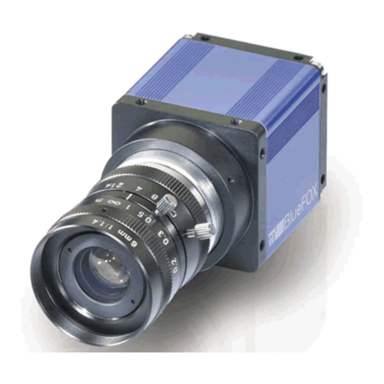
6 Introduction 6 Introduction The mvBlueFOX is a compact industrial CCD & CMOS camera solution for any PC with a Hi-Speed USB (USB 2.0) port. A superior image quality makes it suited for most applications. Integrated preprocessing like binning reduces the PC load to a minimum. The standard Hi-Speed USB interface guarantees an easy integration without any additional interface board. -
Page 27: Mvbluefox-M
2: Glass 3: Daylight cut 9: None - (3): Case 1: Color blue (standard) 2: Color black, no logo, no label MATRIX VISION 3: Color blue, no logo, no label MATRIX VISION 9: None - (4): Misc 1: None (standard) 6.3 mvBlueFOX-M... -
Page 28: Mvbluefox-Mlc
1: None (standard) 2: With I/O #08727 6.5 mvBlueFOX-MLC The mvBlueFOX-MLC nomenclature scheme is as follows: mvBlueFOX-MLC A B - C D E - (1) (2) (3) (4) - A: Sensor model 200w: 0.4 Mpix, 752 x 480, 1/3", CMOS 202b: 1.2 Mpix, 1280 x 960,... -
Page 29: What's Inside And Accessories
• mvBlueFOX • mvIMPACT CD-ROM or DVD-ROM with example application and manual • instruction leaflet For the first use of the mvBlueFOX we recommend the following accessories to get the camera up and running: • A USB 2.0 cable Attention According to the customer and if the mvBlueFOX-MLC is shipped without lensholder, the mvBlueFOX-MLC will be shipped with a protective foil on the sensor. - Page 30 6.6 What's inside and accessories KS-MLC-IO-W mvBlueFOX-MLC board-to-wire I/O data cable, Molex 0510211200 with crimp terminal 50058. Length: up to 1m KS-MLC-USB2-IO-W mvBlueFOX-MLC board-to-wire I/O data and USB 2.0 cable, Molex 0510211200 with crimp terminal 50058 to USB2-A. Length: up to 1m MV-Lensholder BFM-C C-mount lensholder for mvBlueFOX-M,incl.
-
Page 31: Quickstart
"a required section in the INF file could not be found". The camera will not be accessible then. The mvBlueFOX is a USB 2.0 compliant camera device and needs therefore a functioning USB 2.0 port. If you are not sure about this, please follow these steps: 1. -
Page 32: Installing The Mvimpact Acquire Driver
7.1.2 Installing the mvIMPACT Acquire driver Warning Before connecting the mvBlueFOX, please install the software and driver first! To install the software and driver insert the mvIMPACT CD-ROM or DVD-ROM into your CD drive or download the latest driver from our website: https://www.matrix-vision.com "Products -... - Page 33 • "mvBlueFOX driver" This is also not selectable. • "Tools" This feature contains tools for the mvBlueFOX (e.g. to configure MATRIX VISION devices (mvDevice Configure) or to acquire images (wxPropView)). • "Developer API" The Developer API" contains the header for own programming. Additionally you can choose the examples, which installs the sources of wxPropView and three mini samples.
-
Page 34: Installing The Hardware
7.1.3 Installing the hardware Warning Before connecting the mvBlueFOX, please install the software and driver first! It is not necessary to shutdown your system. On an USB port, it is possible to hot plug any USB device (hot plug lets you plug in new devices and use them immediately). - Page 35 If using the Binder connector first connect the cable to the camera, then connect the camera to the PC. Plug the mvBlueFOX to an USB 2.0 Port. After plugging the mvBlueFOX Windows® shows "Found New Hardware" and starts the Windows Hardware Wizard.
- Page 36 Microsoft. You have to select 'Continue anyway' otherwise, the driver can't be installed. If you don't want to install a driver that is not signed you must stop the installation but can't work with the mvBlueFOX camera then.
- Page 37 After the Windows® Logo testing, you have to click "Finish" to complete the installation. Figure 11: Windows Hardware Wizard - Complete the installation Now, you can find the installed mvBlueFOX in the Windows® "Device Manager" under image devices. MATRIX VISION GmbH...
-
Page 38: Linux
7.2 Linux Figure 12: Windows Device Manager - Installed mvBlueFOX After this installation, you can acquire images with the mvBlueFOX. Simply start the application wxPropView (p. 77) (wxPropView.exe) from mvBlueFOX/bin. See also wxPropView (p. 77) 7.2 Linux 7.2.1 System Requirements Kernel requirements Kernel 2.6.x .. - Page 39 • Install the wxWidgets "wxGTK" and "wxGTK-develop" RPMs. Others that will be automatically installed due to dependencies include "wxGTK-compat" and "wxGTK-gl". Although the MATRIX VISION software does not use the ODBC database API the SuSE version of wxWidgets has been compiled with ODBC support and the RPM does not contain a dependency to automatically install ODBC.
-
Page 40: Installing The Mvimpact Acquire Driver
7.2.2 Installing the mvIMPACT Acquire driver To use the mvBlueFOX camera within Linux (grab images from it and change its settings), a driver is needed, consisting of several libraries and several configuration files. These files are required during run time. - Page 41 Note If you want to install the mvBlueFOX Linux driver without installer script manually, please have a look at the following chapter: 7.2.2.1 Installing the mvIMPACT Acquire driver manually Note We recommend to use the installer script to install the mvBlueFOX driver (p.
- Page 42 3. You can now install the mvBlueFOX libraries as follows: • create a new directory somewhere on your system. • copy the correct mvbluefox package file to this directory and change into this directory with "cd" The mvBlueFOX libraries are supplied as a "tgz"...
- Page 43 Current Gentoo systems support udev with a minimal, legacy hotplug system. It is usually sufficient to add any usernames that are to be used for the mvBlueFOX to the group because there is already a udev rule giving "usb" write permission to all USB devices to members of this group. If this does not work then try the other alternatives described here.
- Page 44 Note This is considered a security risk by some experts. If you have been using the mvBlueFOX with one user (e.g. root) and want to try it as another user you should remove the complete directory "/tmp/mv/" , which may contain several files of zero length. These files are used to control mutexes within the software and will be owned by the first user.
- Page 45 CONTENTS 7.2.2.6.2 Power Down Mode To try out the new power down mode you will need to update the firmware on the mvBlueFOX to at least version 39. There is a simple text-based utility to do this in "apps/FirmwareUpgrade" . Just build the application and start on the platform of your choice giving the serial number of the connected mvBlueFOX as a parameter.
-
Page 46: Installing The Hardware
The driver for Linux does not include hot-plugging support at the application level. I.e. a running application will not be informed of new mvBlueFOX devices that have been plugged in and will probably crash if an mvBlueFOX camera is unplugged whilst it is being used. You need to stop the application, plug in the new camera and then restart the application. -
Page 47: Fpga
FPGA file will be the one used by an application. Before using custom FPGA files, please check with MATRIX VISION about why and if this makes sense for your application. -
Page 48: Firmware
Figure 18: Firmware file will be downloaded during an firmware update... When then re-attaching the device to the host system, the new firmware version will become active: Figure 19: ... after repowering the device it will be active MATRIX VISION GmbH... -
Page 49: Settings Behaviour During Startup
A setting e.g. might contain • the gain to be applied to the analogue to digital conversion process for analogue video sources or • the AOI to be captured from the incoming image data. MATRIX VISION GmbH... - Page 50 XML file with the product string as the filename, the device family specific setting will be an XML file with the device family name as the file name. All other XML files containing settings will be ignored! MATRIX VISION GmbH...
- Page 51 One version of the tool will always be delivered in source so it can be used as a reference to find out how to get the desired information from the device driver. MATRIX VISION GmbH...
-
Page 52: Technical Data
8.2 Standard version (mvBlueFOX-xxx) 8 Technical data 8.1 Power supply Symbol Comment Unit mvBlueFOX power supply via USB 4.75 5.25 USBPOWER_IN (@ 5V / 40MHz) USBPOWER_IN (Power Off Mode - only with USBPOWER_IN mvBlueFOX-IGC / mvBlueFOX-MLC) 8.2 Standard version (mvBlueFOX-xxx) 8.2.1 Dimensions and connectors... - Page 53 CONTENTS Figure 3: D-Sub 9-pin (male), digital I/O MATRIX VISION GmbH...
- Page 54 8.2 Standard version (mvBlueFOX-xxx) Signal Description IN0- Negative terminal of opto-isolated input OUT0- Negative terminal of opto-isolated output (emitter of npn-phototransistor) OUT1- Negative terminal of opto-isolated output (emitter of npn-phototransistor) IN1- Negative terminal of opto-isolated input IN0+ Positive terminal of opto-isolated input...
- Page 55 [mA] Output 100 (on state current) Figure 6: DigOut mvBlueFOX-xxx 8.2.1.1.3 Connecting flash to digital output You can connect a flash in series to the digital outputs as shown in the following figure, however, you should only use LEDs together with a current limiter:...
- Page 56 Signal USBPOWER_IN Shell shield Note The mvBlueFOX is an USB device! Attention Do not connect both USB ports at the same time. 8.2.1.3 4-pin circular plug-in connector with lock (USB 2.0) Figure 9: 4-pin circular plug-in connector (female) MATRIX VISION GmbH...
-
Page 57: Led States
USB). The pin assignment corresponds to the description of 'R' version. While mvBlueFOX is connected and powered via standard USB, it is possible to connect additional power via circular connector (only power; the data lines must be disconnected!). Only in this case, the power switch will change the power supply, if the current entry via standard USB is equal to or under the power supply of "circular connector". -
Page 58: Board-Level Version (Mvbluefox-Mxxx)
• ambient temperature storage: -20..60 deg C / 20..90 RH Additional features of mvBlueFOX-2xx: • 8 Mega-pixel image memory (FiFo) • new ADC • 10 Bit mode 8.3 Board-level version (mvBlueFOX-Mxxx) 8.3.1 Dimensions and connectors Figure 10: mvBlueFOX-M12x (CCD) with C-mount MATRIX VISION GmbH... - Page 59 Type "FB" C-Mount 17.526 CS-Mount 12.526 Figure 12: Backside view of the board Note The mvBlueFOX-M has a serial I²C bus EEPROM with 64 KBit of which 512 Bytes can be used to store custom arbitrary data. MATRIX VISION GmbH...
- Page 60 24 V output (10mA) Ground Manufacturer: JST Part number: B12B-PH-K Attention Do not connect Dig I/O signals to the FPGA pins until the mvBlueFOX-M has been started and configured. Otherwise, you will risk damaging the mvBlueFOX-M hardware! MATRIX VISION GmbH...
- Page 61 9.8 (.386) 1.000 22.0 (.866) 25.8 (1.016) 1.000 Material and finish: nylon 66, UL94V-0, natural (white) Manufacturer: JST Part number: PHR-4 / PHR-12 See also Suitable assembled cable accessories for mvBlueFOX-M: What's inside and accessories (p. 22) MATRIX VISION GmbH...
- Page 62 8.3 Board-level version (mvBlueFOX-Mxxx) 8.3.1.5 Characteristics of the mvBlueFOX-Mxxx digital I/Os 8.3.1.5.1 Dig I/O max. values Symbol Comment Unit Input voltage DIG_IN 8.3.1.5.2 Characteristics of the digital inputs Symbol Comment Unit low level input voltage (I = 1.67mA) DIG_IN_LOW high level input voltage (I = 1.67mA)
-
Page 63: Led States
The Dig I/O are connected directly via a resistor to the FPGA pins and therefore they are not protected. For this reason, an application has to provide a protection circuit to the digital I/O of mvBlueFOX-M. Note The Dig I/O characteristics of the mvBlueFOX-M are not compatible to the Dig I/O of the mvBlueFOX standard version. 8.3.2 LED states... - Page 64 8.3 Board-level version (mvBlueFOX-Mxxx) Figure 17: Model 1 with CON5 connector Figure 18: Model 2 with CON1 connector 8.3.4.1.1 CON2 - Flash connector Signal Comment Flash + Flash power MATRIX VISION GmbH Flash - Switched to ground (low side switch)
- Page 65 Voltage (open contact) Flash output capacitance Flash + Internal capacitance storage energy 0.190 Flash capacitance charge current / output DC current Flash On voltage at I 0.15 Off voltage Depends on mvBlueFOX-M power supply Attention: No over-current protection! MATRIX VISION GmbH...
-
Page 66: Single-Board Version (Mvbluefox-Mlc2Xx)
8.4.2 Dimensions and connectors Figure 20: mvBlueFOX-MLC (without S-mount) Note The mvBlueFOX-MLC has a serial I²C bus EEPROM with 16 KByte of which 8 KByte are reserved for the firmware and 8 KByte can be used to store custom arbitrary data. See also... - Page 67 Figure 21: Sensor's optical midpoint and orientation 8.4.2.2 Mini-B USB (USB 2.0) Figure 22: Mini-B USB Signal Comment USBPOWER_IN Supply voltage USB_DATA- Data USB_DATA+ Data Not connected Ground 8.4.2.3 12-pin Wire-to-Board header (USB 2.0 / Dig I/O) MATRIX VISION GmbH...
- Page 68 8.4 Single-board version (mvBlueFOX-MLC2xx) Note If you have the mvBlueFOX-MLC variant which uses the standard Mini-B USB connector, pin 2 and 3 (USB _DATA+ / USB_DATA-) of the header won't be connected! MATRIX VISION GmbH...
- Page 69 CONTENTS Opto-isolated variant TTL compliant variant LVTTL compliant Cable KS- Cable variant (only available MLC-U KS-MLC- for mvBlueFOX-ML SB2-IO-W IO-W C202aG) Signal Comment Signal Comment Signal Comment Ground Ground Ground USB_D Data USB_D Data USB_D Data USB_D ATA+ ATA+ ATA+...
- Page 70 Note I2C bus uses 3.3 Volts. Signals have a 2kOhm pull-up resistor. Access to the I2C bus from an application is possible for mvBlueFOX-MLC devices using an mvBlueFOX driver with version 1.12.44 or newer. Manufacturer (suitable board-to-wire connector): Molex Part number: 0510211200 1.25mm Housing Link: http://www.molex.com/molex/products/datasheet.jsp?part=active/0510211200...
- Page 71 TTL input low level / high level time: Typ. 210ns Digital outputs TTL Figure 24: TTL digital outputs block diagram Comment Unit Dig_out power +-32 =32mA) 5.25 =32mA) 0.55 TTL output low level / high level time: Typ. 40ns Opto-isolated digital inputs MATRIX VISION GmbH...
- Page 72 8.4 Single-board version (mvBlueFOX-MLC2xx) Figure 25: Opto-isolated digital inputs block diagram with example circuit Delay Characteristics Symbol Typ. Unit Turn-On time The inputs can be connected directly to +3.3 V and 5 V systems. If a higher voltage is used, an external resistor must be placed in series (Figure 25).
-
Page 73: Led States
Camera is connected and active Green light on 8.4.4 Assembly variants The mvBlueFOX-MLC is available with following differences: • Mini-B USB connector and digital I/O pin header – 1/1 opto-isolated or 2/2 TTL compliant digital I/O • USB via header without Mini-B USB connector •... -
Page 74: Single-Board Version With Housing (Mvbluefox-Igc2Xx)
8 mm (9.5 mm with max. Ø 20 mm) Note The mvBlueFOX-IGC has a serial I²C bus EEPROM with 16 KByte of which 8 KByte are reserved for the firmware and 8 KByte can be used to store custom arbitrary data. -
Page 75: Led States
Manufacturer: Binder Part number: 79-3107-52-04 8.5.1.2.1 Electrical characteristic Please have a look at the mvBlueFOX-MLC digital I/O characteristics (opto-isolated model) of the 12-pin Wire-to- Board Header (USB / Dig I/O) (p. 59). 8.5.2 LED states State Camera is not connected or defect LED off Camera is connected but not initialized or in "Power off"... -
Page 76: Positioning Tolerances Of Sensor Chip
± 0.1 mm is valid (Figure 32; 1 in the Y-direction ± 0.1 mm; 3 in the Z-direction ± 0.1 mm) There are further sensor specific tolerances, e.g. for model mvBlueFOX-IGC200wG: • Tolerance between sensor chip MT9V034 (die) and its package (connection pad) –... -
Page 77: Sensor Overview
1600 x 1200 gray scale or gray scale or gray scale or gray scale or gray scale or RGB Bayer mo- RGB Bayer mo- RGB Bayer mo- RGB Bayer mo- RGB Bayer mo- saic saic saic saic saic MATRIX VISION GmbH... - Page 78 Trigger (Hard- X / X ware Soft- ware) Pipelined X / - X / - X / - X / - X / - continuous triggered mode Flash con- trol output, synchronous exposure period MATRIX VISION GmbH...
-
Page 79: Cmos Sensors
DR (normal / 55 dB / 61 dB / - 61 dB / 61 dB / 65 dB / HDR (p. 161)) 110 dB (with gray scale version) Progressive scan sensor interlaced problems!) Rolling shutter Global shutter MATRIX VISION GmbH... -
Page 80: Output Sequence Of Color Sensors (Rgb Bayer)
For further information about image errors of image sensors, please have a look at For further information about image errors of image sensors, please have a look at Correcting image errors of a sensor (p. 143). 9.3 Output sequence of color sensors (RGB Bayer) MATRIX VISION GmbH... -
Page 81: Bilinear Interpolation Of Color Sensors (Rgb Bayer)
= --------------- ; = --------------- Any colored edge which might appear is due to Bayer false color artifacts. Note There are more advanced and adaptive methods (like edge sensitive ones) available if the host is doing this debayering. MATRIX VISION GmbH... -
Page 82: Filters
10.2 Cold mirror filter 10 Filters MATRIX VISION offers two filters for the mvBlueFOX camera. The IR filter (p. 75) is part of the standard delivery condition. 10.1 Hot mirror filter The hot mirror filter FILTER IR-CUT 15,5X1,75 FE has great transmission in the visible spectrum and blocks out a significant portion of the IR energy. -
Page 83: Glass Filter
It is also possible to choose the glass filter "FILTER GLASS 15,5X1,75" with following characteristics: Technical data Glass thickness 1.75 mm Material Borofloat without coating ground with protection chamfer Surface quality polished on both sides P4 Surface irregularity 5/3x0.06 on both sides MATRIX VISION GmbH... -
Page 84: Application Usage
11.1 wxPropView wxPropView (p. 77) is an interactive GUI tool to acquire images and to configure the device and to display and modify the device properties of MATRIX VISION GmbH hardware. After the installation you can find wxPropView (p. 77) •... - Page 85 • a host (PC) based sensor specific "Color Correction Matrix" and use the respective "sRGB display matrix". These settings will also be applied whenever the "Color Preset" button is pressed. It is herewith assumed that color camera image is optimized for best human visual feedback. MATRIX VISION GmbH...
- Page 86 Use OK to use the values and settings of the Quick Setup Wizard and go back to the tree mode of wxPropView. Use Cancel to discard the Quick Setup Wizard values and settings and go back to wxPropView and use the former (or default) settings. MATRIX VISION GmbH...
- Page 87 – Europe: 50 Hz; Set frame rate to 100, 50, 25 12.5 fps or appropriate. – In countries with 60 Hz use 120, 60, 30 or 15. . . accordingly. 11.1.1.2 First View of wxPropView wxPropView (p. 77) consists of several areas: Figure 2:wxPropView started MATRIX VISION GmbH...
- Page 88 Therefore, certain properties might appear or disappear when modifying another properties. To permanently commit a modification made with the keyboard the ENTER must be pressed. If leaving the editor before pressing ENTER will restore the old value. MATRIX VISION GmbH...
- Page 89 When the device has been opened successfully, the remaining buttons of the dialog will be enabled: Note Following screenshots are representative and where made using a mvBlueFOX camera as the capturing device. For color sensors, it is recommended to perform a white balance (p. 102) calibration before acquiring images. This will improve the quality of the resulting images significantly.
- Page 90 If you switched on the request info overlay (righ-click on the display area and select the entry to activate this feature), these information will be displayed on the image, too. With the timestamp you can see the interval of the single frames in microseconds. MATRIX VISION GmbH...
- Page 91 Modified properties (even if the value is the same as the default) will be displayed in black. Figure 5: wxPropView - Storing settings MATRIX VISION GmbH...
- Page 92 • explicitly load device family specific settings from a XML file previously created ("From A File") Note With "Action - Capture Settings - Manage..." you can delete the settings which were saved on the system. Figure 6: wxPropView - Restoring settings MATRIX VISION GmbH...
- Page 93 • right click on the name of a list and • select "Restore Default". In this case a popup window will be opened and you have to confirm again. Figure 7: wxPropView - Restore the default value of a property MATRIX VISION GmbH...
- Page 94 Also the user might want to set all (or a certain range of) values for properties that store multiple values with a single operation. If supported by the property, this can also be achieved by right clicking on the PARENT grid element. If the property allows this modification the pop up menu will again contain additional entries: MATRIX VISION GmbH...
- Page 95 It's possible to either set all (or a range of) elements of the property to a certain value OR to define a value range, that then will be applied to the range of property elements selected by the user. The following example will explain how this works: Figure 11: wxPropView - Setting multiple property values within a certain value range MATRIX VISION GmbH...
- Page 96 The return value (in almost every case an error code as an integer) will be displayed in the lower right corner of the tree control. The values displayed here directly correspond the error codes defined in the interface reference and therefore will be of type TDMR_ERROR or TPROPHANDLING_ERROR. MATRIX VISION GmbH...
- Page 97 • by dragging an image file into an image display within wxPropView (p. 77) • by starting wxPropView (p. 77) from the command line passing the file to open as a command line param- eter (p. 115) (under Windows® e.g. "wxPropView.exe MyImage.png" followed by [ENTER]) MATRIX VISION GmbH...
- Page 98 This will result in 1 display in horizontal direction and 2 in vertical direction. Since mvIMPACT Acquire 2.18.1 Is is also possible to change the amount of display at runtime via "Settings - Image Displays - Configure Image Display Count": MATRIX VISION GmbH...
- Page 99 1. Various additional capture setting can be created. In order to understand what a capture setting actually is please refer to • "Working with settings" chapter of the "mvIMPACT Acquire API" manuals. Creating a capture setting is done via "Capture - Capture Settings - Create Capture Setting". Figure 17: wxPropView - Create capture setting MATRIX VISION GmbH...
- Page 100 Figure 19: wxPropView - Create capture setting - Choosing base Afterwards, in this example we end up having 2 capture settings: • a "Base" setting, which is always available • a "NewSetting1", which has been derived from "Base". MATRIX VISION GmbH...
- Page 101 Now, to set up wxPropView (p. 77) to display all images taken using capture setting "Base" in one display and all image taken using capture setting "NewSetting1" in another display the capture settings need to be assigned to image displays via "Capture - Capture Settings - Assign To Display(s)". MATRIX VISION GmbH...
- Page 102 The minimum number of requests needed is 2 times the amount of images displays. The number of requests used by the driver can be set up in the drivers property tree: MATRIX VISION GmbH...
- Page 103 Finally, wxPropView (p. 77) must be configured in order to use all available capture settings in a round-robin scheme. This can be done by setting the capture setting usage mode to "Automatic" via "Capture - Capture Settings - Usage Mode": MATRIX VISION GmbH...
- Page 104 When only one setting shall be used at a given time, this can be achieved by setting the capture setting usage mode back to "Manual" via "Capture - Capture Settings - Usage Mode". Then the setting that shall be used can be manually selected in the request control list: MATRIX VISION GmbH...
- Page 105 (p. 77) shows snapped or live images in the display area of the GUI. The area, however, shows the most significant bits (msb) of the image in the 8 bit display. The following image shows how a mid-grey 12 bit pixel of an image is displayed with 8 bit. Additionally, two shifts are shown. MATRIX VISION GmbH...
- Page 106 View". While the first (default) view will display the device drivers feature tree in a way that might be suitable for most users of a GUI application it might present the features in a slightly different order as they actually are implemented MATRIX VISION GmbH...
- Page 107 Figure 28: Developers View 11.1.1.12 Accessing log files Since mvIMPACT Acquire 2.11.9 Using Windows, it is possible to access the log files generated by MATRIX VISION via the Help menu. Sending us the log files will speed up support cases. MATRIX VISION GmbH...
-
Page 108: How To Configure A Device
Devices belonging to this family only support the Device Specific interface layout which is the common interface layout supported by most MATRIX VISION devices. GenICam compliant devices can be operated in different interface layouts. Have a look at a GenICam compliant device for additional information. - Page 109 11.1.2.2 White balance of a camera device (color version) Start the wxPropView (p. 77) and initialize the device by clicking "Use" and start a "Continuous" acquisition. Figure 30: wxPropView - Starting window Figure 31: wxPropView - Selecting WhiteBalance profile MATRIX VISION GmbH...
- Page 110 11.1 wxPropView Figure 32: wxPropView - WhiteBalanceCalibration Figure 33: wxPropView - White balance summary MATRIX VISION GmbH...
- Page 111 (Analysis tabs). Whenever an event is send by the device that updates one of the properties a callback has been attached to, the output window will print a message with some information about the detected change. MATRIX VISION GmbH...
- Page 112 Figure 34: wxPropView - Call refresh 11.1.2.5 Setting up external trigger and flash control To set up external trigger and flash control, following things are required: • mvBlueFOX with CCD sensor • Host PC with USB 2.0 interface • USB 2.0 cable with max. 5m •...
- Page 113 External trigger signal Signal for triggering image acquisition must be connected to digital input on backside of mvBlueFOX on D-Sub 9-pin connector (p. 45). You can choose either input IN0 (pin 6 and 1) or IN1 (pin 9 and 4) for triggering.
- Page 114 6 (+) As long as the power supply is connected, you can see a live preview. If you disconnect the power supply the live preview should stop. If this is working the trigger input works. MATRIX VISION GmbH...
- Page 115 Figure 37: Settings to test the general trigger functionality External flash signal For supplying flash with control signal use any digital output Out0 (pin 7 and 2) or Out1 (pin 8 and 3) on 9 pin D-Sub connector. MATRIX VISION GmbH...
- Page 116 By default camera is running free. This means, it uses its own timing depending on set pixel clock, exposure time and shutter mode. Trigger To let the camera acquire images only with an external trigger signal you must change the "TriggerMode" to the mode suitable to your application: Figure 39: TriggerMode MATRIX VISION GmbH...
- Page 117 CONTENTS MATRIX VISION GmbH...
- Page 118 OnAnyEdge Start the exposure of a frame when the trigger input level changes from high to low or from low to high. Now, define on which pin the trigger signal is connected to. Figure 40: TriggerSource MATRIX VISION GmbH...
- Page 119 You can set this value in "ImageRequestTimeout" property: Figure 42: ImageRequestTimeout Trigger To activate flash control signal set "FlashMode" to the output you connected flash or flash driver to: MATRIX VISION GmbH...
- Page 120 If both formats are set to "Auto", 8 bit will be used. If you set "LUTImplementation" to "Software" in "Setting - ImageProcessing - LUTOperations", the hardware Look-Up-Table (LUT) will work with 8 bit data ("LUTMappingSoftware = 8To8"). Using Gamma functions you will see gaps in the histogram: MATRIX VISION GmbH...
- Page 121 ImageProcessing - LUTOperations", the hardware Look-Up-Table (LUT) will work with 10 bit data inside the camera and converts the data to 8 bit for output ("LUT MappingHardware = 10To8"). Now, there will be no gaps in the histogram: MATRIX VISION GmbH...
-
Page 122: Command-Line Options
11.1 wxPropView Figure 45: 10to8 hardware LUT shows no in the histogram (screenshot: mvBlueFOX-MLC) 11.1.3 Command-line options It is possible to start wxPropView via command line and controlling the starting behavior using parameters. The supported parameter are as follows: Parameter... -
Page 123: Mvdeviceconfigure
This will start the first available device, will hide the Quick Setup Wizard, and will display the complete property tree. 11.2 mvDeviceConfigure mvDeviceConfigure (p. 116) is an interactive GUI tool to configure MATRIX VISION devices. It shows all connected devices. - Page 124 11.2.1.2 Step 2: Open dialog to set the ID With the device selected, select the menu item Action and click on Set ID. Note It is also possible to select the action with a right click on the device. Figure 48: mvDeviceConfigure - Select action MATRIX VISION GmbH...
-
Page 125: How To Update The Firmware
11.2.2 How to update the firmware With the mvDeviceConfigure tool it is also possible to update the firmware. These steps are necessary: 11.2.2.1 Step 1: Device selection Select the device you want to update from the list box. MATRIX VISION GmbH... - Page 126 It is also possible to select the action with a right click on the device. Figure 51: mvDeviceConfigure - Select action 11.2.2.3 Step 3: Confirm the firmware update You have to confirm the update. Figure 52: mvDeviceConfigure - Confirm update MATRIX VISION GmbH...
-
Page 127: How To Disable Cpu Sleep States A.k.a. C States ( Windows 8)
ACPI standard. The standard defines several power states. For example, if processor load is not needed the processor changes to a power saving (sleep) state automatically and vice versa. Every state change will stop the processor for microseconds. This time is enough to cause image error counts! MATRIX VISION GmbH... - Page 128 Thus in order to permanently disable the sleep states, this needs to be done for all power schemes that will be used when operating devices. 1. Start mvDeviceConfigure. 2. Go to tab "Settings" and unselect "CPU Idle States Enabled" MATRIX VISION GmbH...
-
Page 129: Command-Line Options
AND by product. The application will first try to locate a device with a serial number matching the specified string and then (if no suitable device is found) a device with a MATRIX VISION GmbH matching product string. - Page 130 This will update the firmware of ALL mvBlueFOX devices in the current system. mvDeviceConfigure update_fw=mvBlueFOX-2 * lf=output.txt quit This will update the firmware of ALL mvBlueFOX-2 devices in the current system, then will store a log file of the executed operations and afterwards will terminate the application.
-
Page 131: Hrtc - Hardware Real-Time Controller
(C++ syntax): CameraSettings->triggerMode = ctmOnRisingEdge CameraSettings->triggerSource = ctsRTCtrl When working with wxPropView (p. 77) this are the properties to modify in order to activate the evaluation of the HRTC program: MATRIX VISION GmbH... - Page 132 – Take two images after one external trigger (HRTC) (p. 183) – Take two images with different expose times after an external trigger (HRTC) (p. 184) • "Using multiple cameras" : – Delay the expose start of the following camera (HRTC) (p. 188) MATRIX VISION GmbH...
-
Page 133: C Developers
The description for the mvIMPACT Acquire SDK for C developers is available as a separate file: mvIMPACT_ Acquire_API_C_manual.chm which is • either part of the installed package or • online from https://www.matrix-vision.com Here an online version of the documentation is available as well. MATRIX VISION GmbH... -
Page 134: C++ Developers
The description for the mvIMPACT Acquire SDK for C++ developers is available as a separate file: mvIMPACT_ Acquire_API_CPP_manual.chm which is • either part of the installed package or • online from https://www.matrix-vision.com Here an online version of the documentation is available as well. MATRIX VISION GmbH... -
Page 135: Net Developers
The description for the mvIMPACT Acquire SDK for .NET developers is available as a separate file: mvIMPACT _Acquire_API_NET_manual.chm which is • either part of the installed package or • online from https://www.matrix-vision.com Here an online version of the documentation is available as well. MATRIX VISION GmbH... -
Page 136: Python Developers
'mvIMPACT Acquire for python' for Python versions 2.7 to 3.2: https://www.microsoft.com/en-us/download/details.aspx?id=44266 The use of this compiler packet has been tested by MATRIX VISION and it is is highly recommended. When installing the mvIMPACT Acquire Python API on a target system all files needed for building the actual extension module can be found in /mvIMPACT_Python. -
Page 137: Linux
# If you want to use this module in your code feel free to do so but make sure the ’Common’ folder resides in a sub-folder of your project then from Common import # For systems with NO mvDisplay library support #import ctypes #import Image MATRIX VISION GmbH... - Page 138 #else: img = Image.fromarray(arr, ’RGBA’ if alpha else ’RGB’) pPreviousRequest != None: pPreviousRequest.unlock() pPreviousRequest = pRequest fi.imageRequestSingle() else: print("imageRequestWaitFor failed (" + str(requestNr) + ", " + ImpactAcquireException. getErrorCodeAsString(requestNr) + ")") manuallyStopAcquisitionIfNeeded(pDev, fi) raw_input("Press Enter to continue...") MATRIX VISION GmbH...
- Page 139 The above code uses the Python 3 style print. Because of the line from __future__ import print_function This will also work with Python versions starting with version 2.6. For smaller versions of Python the code needs to be changed! MATRIX VISION GmbH...
-
Page 140: Directshow Interface
17.1.6 ISpecifyPropertyPages 17.2 Logging The DirectShow_acquire logging procedure is equal to the logging of the MATRIX VISION products which uses mvIMPACT Acquire. The log output itself is based on XML. If you want more information about the logging please have a look at the Logging chapter of the respective "mvI MPACT Acquire API"... -
Page 141: Registering And Renaming Devices For Directshow Usage
. I.e. if you have installed the 32 bit version of the VLC Media Player, Virtual Dub, etc., you have to register the MV device with the 32 bit version of mvDeviceConfigure (p. 116) ("C:\Program Files\MATRIX VISION\mvI MPACT Acquire\bin") ! 17.3.1 Registering devices... - Page 142 17.3 Registering and renaming devices for DirectShow usage Figure 2: mvDeviceConfigure - register all devices 3. After a successful registration the column "registered for DirectShow" will display 'yes' for every device and the devices will be registered with a default DirectShow friendly name. MATRIX VISION GmbH...
-
Page 143: Renaming Devices
2. Now, select the device you want to rename, click the right mouse button and select "Set DirectShow friendly name": Figure 4: mvDeviceConfigure - set DirectShow friendly name 3. Then, a dialog will appear. Please enter the new name and confirm it with "OK". MATRIX VISION GmbH... -
Page 144: Make Silent Registration
The following command line options are available an can be passed during the silent registration: EXAMPLES: Register ALL devices that are recognized by mvIMPACT Acquire (this will only register devices which have drivers installed). regsvr32 <path> DirectShow_acquire.ax /s MATRIX VISION GmbH... -
Page 145: Troubleshooting
// <- Change the directory user@linux-desktop:/home/workspace/apps/mvPropView/x86/$ ./wxPropView // <- Start the executable Afterwards, several log files are generated which are listed in files.mvloglist . The log files have the file extension .mvlog. Please send these files to our support team. MATRIX VISION GmbH... -
Page 146: Use Cases
19.1.1 Generating very long exposure times Since mvIMPACT Acquire 1.10.65 Very long exposure times are possible with mvBlueFOX. For this purpose a special trigger/IO mode is used. You can do this as follows (pseudo code): TriggerMode = OnHighExpose TriggerSource = DigOUT0 - DigOUT3... -
Page 147: Using Vlc Media Player
CONTENTS 19.1.2 Using VLC Media Player With the DirectShow Interface (p. 133) MATRIX VISION devices become a (acquisition) video device for the VLC Media Player. Figure 1: VLC Media Player with a connected device via DirectShow 19.1.2.1 System requirements It is necessary that following drivers and programs are installed on the host device (laptop or PC): •... - Page 148 I.e. if you have installed the 32 bit version of the VLC Media Player, you have to register the MV device with the 32 bit version of mvDeviceConfigure (p. 116) ("C:/Program Files/MATRIX VISION/mvIMPACT Acquire/bin") 1. Connect the MV device to the host device directly or via GigE switch using an Ethernet cable.
-
Page 149: Improving The Acquisition / Image Quality
5. Finally, click on "Play" . After a short delay you will see the live image of the camera. 19.2 Improving the acquisition / image quality There are several use cases concerning the acquisition / image quality of the camera: MATRIX VISION GmbH... -
Page 150: Correcting Image Errors Of A Sensor
19.2.1 Correcting image errors of a sensor Due to random process deviations, technical limitations of the sensors, etc. there are different reasons that image sensors have image errors. MATRIX VISION provides several procedures to correct these errors, by default these are host-based calculations. - Page 151 (Settings can be saved in the Windows registry or in a file) Note After having re-started the camera you have to reload the capture settings vice versa. The filter checks: Pixel > LeakyPixelDeviation_ADCLimit // (default value: 50) All pixels above this value are considered as leaky pixel. MATRIX VISION GmbH...
- Page 152 After having re-started the camera you have to reload the capture settings vice versa. The filter checks: Pixel < T[cold] // (default value: 15 %) // T[cold] = deviation of the average gray value (ColdPixelDeviation_pc) All pixels below this value have a dynamic below normal behavior. MATRIX VISION GmbH...
- Page 153 The longer the exposure, the greater the dark current part. I.e. using long exposure times, the dark current itself could lead to an overexposed sensor chip 2. Temperature By cooling the sensor chips the dark current production can be highly dropped (approx. every 6 °C the dark current is cut in half) MATRIX VISION GmbH...
- Page 154 "Action - Capture Settings - Save Active Device Settings" (Settings can be saved in the Windows registry or in a file) The filter snaps a number of images and averages the dark current images to one correction image. MATRIX VISION GmbH...
- Page 155 CONTENTS Note After having re-started the camera you have to reload the capture settings vice versa. Figure 3: Image corrections (screenshot mvBlueFOX): OffsetAutoCalibration = Off MATRIX VISION GmbH...
- Page 156 Between flat-field correction and the future application you must not change the optic. To reduce errors while doing the flat-field correction, a saturation between 50 % and 75 % of the flat-field in the histogram is convenient. MATRIX VISION GmbH...
- Page 157 After having re-started the camera you have to reload the capture settings vice versa. The filter snaps a number of images (according to the value of the CalibrationImageCount , e.g. ) and averages the flat-field images to one correction image. MATRIX VISION GmbH...
-
Page 158: Optimizing The Color Fidelity Of The Camera
RAW data to the host can be recom- mended. Of course host based settings can be used with all families of cameras (e.g. also mvBlueFOX). Host based settings are: •... - Page 159 Figure 2: SingleFrame snap without color optimization Figure 3: Corresponding histogram of the horizontal white to black profile As you can see, • saturation is missing, • white is more light gray, • black is more dark gray, • etc. MATRIX VISION GmbH...
- Page 160 First of all, a Gamma correction (Luminance) can be performed to change the image in a way how humans perceive light and color. For this, you can change either • the exposure time, • the aperture or • the gain. MATRIX VISION GmbH...
- Page 161 Base - Camera You can turn them "On" or "Off". Using the auto controls you can set limits of the auto control; without you can set the exact value. After gamma correction, the image will look like this: MATRIX VISION GmbH...
- Page 162 19.2 Improving the acquisition / image quality Figure 6: After gamma correction Figure 7: Corresponding histogram after gamma correction MATRIX VISION GmbH...
- Page 163 Please have a look at White balance of a camera device (color version) (p. 102) for more information for an automatic white balance. To adapt the single colors you can use the "WhiteBalanceSettings-1". After optimizing white balance, the image will look like this: MATRIX VISION GmbH...
- Page 164 Still, black is more a darker gray. To optimize the contrast you can use "Setting - Base - ImageProcessing - LUTControl" as shown in Figure 8. The image will look like this now: Figure 11: After adapting contrast MATRIX VISION GmbH...
- Page 165 2. click on "Wizard" to start the saturation via "Color Transformation Control" wizard tool (since firmware version 1.4.57). Figure 13: Selected Color Twist Enable and click on wizard will start wizard tool 3. Now, you can adjust the saturation e.g. "1.1". MATRIX VISION GmbH...
- Page 166 8. As you can see, the correction is done by the host ("Host Color Correction Controls"). Note It is not possible to save the settings of the "Host Color Correction Controls" in the mvBlueFOX. Unlike in the case of Figure 14, the buttons to write the "Device Color Correction Controls" to the mvBlueFOX are not active.
-
Page 167: Working With Triggers
Figure 16: Corresponding histogram after adapting saturation 19.3 Working with triggers There are several use cases concerning trigger: 19.3.1 Using external trigger with CMOS sensors 19.3.1.1 Scenario The CMOS sensors used in mvBlueFOX cameras support the following trigger modes: • Continuous • OnDemand (software trigger) •... -
Page 168: Working With Hdr (High Dynamic Range Control)
19.3.1.2.1 External synchronized image acquisition (high active) Note Using mvBlueFOX-MLC or mvBlueFOX-IGC, you have to select DigIn0 as the trigger source, because the camera has only one opto-coupled input. Only the TTL model of the mvBlueFOX-MLC has two I/O's. • Trigger modes –... - Page 169 For this reason, darker pixels can be integrated during the complete integration time and the sensor reaches its full sensitivity. Pixels, which are limited at each Knee Points, lose a part of their integration time - even more, if they are brighter. MATRIX VISION GmbH...
- Page 170 S2 = 2 x S1 and S3 = 3 x S1, a hundredfold brightness of one pixel's step from S2 to S3, compared to the step from 0 and S1 is needed. 19.4.1.3 Using HDR with mvBlueFOX-x00w Figure 3 is showing the usage of the HDR mode. Here, an image sequence was created with the integration time between 10us and 100ms.
- Page 171 CONTENTS 19.4.1.3.1 Notes about the usage of the HDR mode with mvBlueFOX-x00w • In the HDR mode, the basic amplification is reduced by approx. 0.7, to utilize a huge, dynamic area of the sensor. • If the manual gain is raised, this effect will be reversed.
-
Page 172: Adjusting Sensor -X02D (-1012D)
The longest exposure time (T1) represents the Exposure_us parameter you can set in wxPropView. Afterwards, the signal is fully linearized before going through a compander to be output as a piece-wise linear signal. the next figure shows this. MATRIX VISION GmbH... - Page 173 Increasing R1 and R2 will increase the dynamic range of the sensor at the cost of lower signal-to-noise ratio (and vice versa). 19.4.2.2.2 Possible settings Possible settings of the mvBlueFOX-x02d in HDR mode are: • "HDREnable": – "Off": Standard mode –...
-
Page 174: Working With Luts
19.5 Working with LUTs Figure 3: wxPropView - Working with the HDR mode 19.5 Working with LUTs There are several use cases concerning LUTs (Look-Up-Tables): MATRIX VISION GmbH... -
Page 175: Introducing Luts
LUTOperations"). Here, the changes will affect the 8 bit image data and the processing needs the CPU of the host system. The mvBlueFOX cameras also feature a hardware based LUT. Although, you have to set the LUT via "Setting - Base - ImageProcessing - LUTOperations", you can set where the processing takes place. - Page 176 This is one way to get an inverted result. It is also possible to use the "LUTMode" - "Interpolated". 4. Now you can set the range from 0 to 255 and the values from 255 to 0 as shown in Figure 2. MATRIX VISION GmbH...
-
Page 177: Saving Data On The Device
You can find further information about for example the XML compati- bilities of the different driver versions in the mvIMPACT Acquire SDK manuals and the according set- ting classes: https://www.matrix-vision.com/manuals/SDK_CPP/classmvIMPACT_1_ 1acquire_1_1FunctionInterface.html (C++) There are several use cases concerning device memory: MATRIX VISION GmbH... -
Page 178: Creating User Data Entries
It is possible to save arbitrary user specific data on the hardware's non-volatile memory. The amount of possible entries depends on the length of the individual entries as well as the size of the devices non-volatile memory reserved for storing: • mvBlueFOX, • mvBlueFOX-M, • mvBlueFOX-MLC, •... - Page 179 Figure 2, to see if the write process returned with no errors. If an error occurs a message box will pop up. Figure 2: wxPropView - analysis tool "Output" MATRIX VISION GmbH...
-
Page 180: Working With Device Features
19.8.1 Using 2 mvBlueFOX-MLC cameras in Master-Slave mode 19.8.1.1 Scenario If you want to have a synchronized stereo camera array (e.g. mvBlueFOX-MLC-202dG) with a rolling shutter master camera (e.g. mvBlueFOX-MLC-202dC), you can solve this task as follows: 1. Please check, if all mvBlueFOX cameras are using firmware version 1.12.16 or newer. - Page 181 HRTC program which sets the trigger signal and the digital output. The sample will lead to a constant frame rate of 16 fps (50000 us + 10000 us = 60000 us for one cycle. 1 / 60000 us 1000000 = 16.67 Hz). MATRIX VISION GmbH...
- Page 182 19.8 Working with several cameras simultaneously Figure 2: wxPropView - HRTC program sets the trigger signal and the digital output Do not forget to set HRTC as the trigger source for the master camera. MATRIX VISION GmbH...
- Page 183 3. Then, set the slave with wxPropView (p. 77) : Figure 4: wxPropView - Slave camera with TriggerMode "OnHighLevel" at DigIn 0 19.8.1.1.1 Connection using -UOW versions (opto-isolated inputs and outputs) The connection of the mvBlueFOX cameras should be like this: MATRIX VISION GmbH...
- Page 184 You can add further slaves. 19.8.1.1.2 Connection using -UTW versions (TTL inputs and outputs) The connection of the mvBlueFOX cameras should be like this: Figure 6: Connection with TTL digital inputs and outputs For this case we offer a synchronization cable called "KS-MLC-IO-TTL 00.5".
-
Page 185: Synchronize The Cameras To Expose At The Same Time
This can be achieved by connecting the same external trigger signal to one of the digital inputs of each camera like it's shown in the following figure: Figure 1: Electrical setup for sync. cameras Each camera then has to be configured for external trigger somehow like in the image below: MATRIX VISION GmbH... -
Page 186: Working With The Hardware Real-Time Controller (Hrtc)
19.9 Working with the Hardware Real-Time Controller (HRTC) Note Please have a look at the Hardware Real-Time Controller (HRTC) (p. 124) chapter for basic information. There are several use cases concerning the Hardware Real-Time Controller (HRTC): • "Using single camera": • "Using multiple cameras": MATRIX VISION GmbH... -
Page 187: Single Camera Samples (Hrtc)
So to get e.g. exactly 10 images per second from the camera the program would somehow look like this(of course the expose time then must be smaller or equal then the frame time in normal shutter mode): 0. WaitClocks 99000 1. TriggerSet 1 2. WaitClocks 1000 3. TriggerReset 4. Jump 0 MATRIX VISION GmbH... - Page 188 Please note the max. frame rate of the corresponding sensor! To see a code sample (in C++) how this can be implemented in an application see the description of the class mvIMPACT::acquire::RTCtrProgram (C++ developers) 19.9.1.2 Delay the external trigger signal (HRTC) MATRIX VISION GmbH...
- Page 189 Between TriggerSet and TriggerReset has to be a waiting period. If you are waiting for an external edge in a HRTC sequence like WaitDigIn[On,Ignore] WaitDigIn[Off,Ignore] the minimum pulse width which can be detected by HRTC has to be at least 5 us. MATRIX VISION GmbH...
- Page 190 2. WaitClocks <trigger pulse width> 3. TriggerReset 4. WaitClocks <time between 2 acquisitions - 10us> (= WC1) 5. TriggerSet 2 6. WaitClocks <trigger pulse width> 7. TriggerReset 8. Jump 0 <trigger pulse width> should not less than 100us. MATRIX VISION GmbH...
- Page 191 WaitClocks <time between 2 acquisitions - expose time image1 - 10us> (= WC2) ExposeSet WaitClocks <expose time image2 - 10us> (= WC3) 10. TriggerSet 2 11. WaitClocks <trigger pulse width> 12. TriggerReset 13. ExposeReset 14. Jump 0 <trigger pulse width> should not less than 100us. MATRIX VISION GmbH...
- Page 192 "int Load( )" to load the HRTC program. There are timeouts added in line 4 and line 14 to illustrate the different exposure times. Using a CMOS model (e.g. the mvBlueFOX-MLC205), a sample with four consecutive exposure times (10ms / 20ms / 40ms / 80ms) triggered just by one hardware input signal would look like this: WaitDigin DigIn0->On...
- Page 193 4. the trigger will be reset (step 4). 5. Now, the HRTC program waits for a falling edge at the digital input 0 (step 5). 6. If there is a falling edge, the trigger will jump to step 0 (step 6). MATRIX VISION GmbH...
- Page 194 . How you can work with capture settings is described in the following chapter EdgeControl.xml (p. 84). To see a code sample (in C++) how this can be implemented in an application see the description of the class mvIMPACT::acquire::RTCtrProgram (C++ developers) MATRIX VISION GmbH...
-
Page 195: Multiple Camera Samples (Hrtc)
0. WaitDigin DigIn0->On 1. TriggerSet 0 2. WaitClocks <trigger pulse width> 3. TriggerReset 4. WaitClocks <delay time> 5. SetDigout DigOut0->On 6. WaitClocks 100us 7. SetDigout DigOut0->Off 8. Jump 0 <trigger pulse width> should not less than 100us. MATRIX VISION GmbH... - Page 196 If more than two cameras shall be connected like this, every camera except the last one must run a program like the one discussed above. The delay times of course can vary. Figure 2: Delay the expose start of the following camera MATRIX VISION GmbH...
-
Page 197: Appendix A.1 Ccd Specific Camera / Sensor Data
CONTENTS 20 Appendix A.1 CCD specific camera / sensor data 20.1 mvBlueFOX-[Model]220 (0.3 Mpix [640 x 480]) 20.1.1 Introduction The CCD sensor is a highly programmable imaging module which will, for example, enable the following type of applications Industrial applications: •... -
Page 198: Ccd Timing
20.1 mvBlueFOX-[Model]220 (0.3 Mpix [640 x 480]) See also For detailed description about the trigger modes ( https://www.matrix-vision/manuals/ [mvI MPACT Acquire API]) • C: TCameraTriggerMode • C++: mvIMPACT::acquire::TCameraTriggerMode 20.1.2.2 Exposure aka Integration After an active trigger, the exposure phase starts with a maximum jitter of t . -
Page 199: Reprogramming Ccd Timing
2. Time to initialize (erase) the CCD chip after reprogramming this is fixed, abt 4.5 ms So for example when reprogramming the capture window you will need (average values) = change_window + init_ccd regprog = 5ms + 4.5ms regprog = 9.5ms regprog MATRIX VISION GmbH... -
Page 200: Ccd Sensor Data
20.1 mvBlueFOX-[Model]220 (0.3 Mpix [640 x 480]) 20.1.5 CCD Sensor Data Device Structure • Interline CCD image sensor • Image size: Diagonal 4.5mm (Type 1/4) • Number of effective pixels: 659 (H) x 494 (V) approx. 330K pixels • Total number of pixels: 692 (H) x 504 (V) approx. 350K pixels •... - Page 201 CONTENTS 20.1.5.2 Color version MATRIX VISION GmbH...
- Page 202 20.1 mvBlueFOX-[Model]220 (0.3 Mpix [640 x 480]) 20.1.5.3 Gray scale version MATRIX VISION GmbH...
- Page 203 CONTENTS MATRIX VISION GmbH...
-
Page 204: Ccd Signal Processing
20.1 mvBlueFOX-[Model]220 (0.3 Mpix [640 x 480]) 20.1.6 CCD Signal Processing The CCD signal is processed with an analog front-end and digitized by an 12 bit analog-to-digital converter (A DC). The analog front-end contains a programmable gain amplifier which is variable from 0db (gain=0) to 30dB (gain=255). -
Page 205: Device Feature And Property List
20.1.7 Device Feature And Property List 20.1.7.1 Gray scale version 20.1.7.2 Color version 20.2 mvBlueFOX-[Model]220a (0.3 Mpix [640 x 480]) 20.2.1 Introduction The CCD sensor is a highly programmable imaging module which will, for example, enable the following type of... -
Page 206: Ccd Timing
20.2 mvBlueFOX-[Model]220a (0.3 Mpix [640 x 480]) Mode Description Continuous Free running, no external trigger signal needed. OnDemand Image acquisition triggered by command (software trigger). OnLowLevel As long as trigger signal is Low camera acquires images with own timing. OnHighLevel As long as trigger signal is High camera acquires images with own timing. - Page 207 See also To find out how to achieve any defined freq. below or equal to the achievable max. freq., please have a look at Achieve a defined image frequency (HRTC) (p. 180). MATRIX VISION GmbH...
-
Page 208: Reprogramming Ccd Timing
20.2 mvBlueFOX-[Model]220a (0.3 Mpix [640 x 480]) 20.2.4 Reprogramming CCD Timing Reprogramming the CCD Controller will happen when the following changes occur • Changing the exposure time • Changing the capture window • Changing Trigger Modes Reprogram time consists of two phases 1. - Page 209 CONTENTS 20.2.5.1 Characteristics These zone definitions apply to both the color and gray scale version of the sensor. 20.2.5.2 Color version MATRIX VISION GmbH...
- Page 210 20.2 mvBlueFOX-[Model]220a (0.3 Mpix [640 x 480]) 20.2.5.3 Gray scale version MATRIX VISION GmbH...
- Page 211 CONTENTS MATRIX VISION GmbH...
-
Page 212: Device Feature And Property List
20.2 mvBlueFOX-[Model]220a (0.3 Mpix [640 x 480]) 20.2.6 Device Feature And Property List 20.2.6.1 Gray scale version 20.2.6.2 Color version MATRIX VISION GmbH... -
Page 213: Mvbluefox-[Model]221 (0.8 Mpix [1024 X 768])
CONTENTS 20.3 mvBlueFOX-[Model]221 (0.8 Mpix [1024 x 768]) 20.3.1 Introduction The CCD sensor is a highly programmable imaging module which will, for example, enable the following type of applications Industrial applications: • triggered image acquisition with precise control of image exposure start by hardware trigger input. -
Page 214: Ccd Timing
20.3 mvBlueFOX-[Model]221 (0.8 Mpix [1024 x 768]) See also For detailed description about the trigger modes ( https://www.matrix-vision/manuals/ [mvI MPACT Acquire API]) • C: TCameraTriggerMode • C++: mvIMPACT::acquire::TCameraTriggerMode 20.3.2.2 Exposure aka Integration After an active trigger, the exposure phase starts with a maximum jitter of t . -
Page 215: Reprogramming Ccd Timing
Achieve a defined image frequency (HRTC) (p. 180). 20.3.4 Reprogramming CCD Timing Reprogramming the CCD Controller will happen when the following changes occur • Changing the exposure time • Changing the capture window • Changing Trigger Modes Reprogram time consists of two phases MATRIX VISION GmbH... -
Page 216: Ccd Sensor Data
20.3 mvBlueFOX-[Model]221 (0.8 Mpix [1024 x 768]) 1. Time needed to send data to the CCD controller depending on what is changed exposure : abt 2..3ms window: abt 4..6ms trigger mode: from 5..90ms, varies with oldmode/newmode combination 2. Time to initialize (erase) the CCD chip after reprogramming this is fixed, abt 4.5 ms... - Page 217 CONTENTS 20.3.5.2 Color version MATRIX VISION GmbH...
- Page 218 20.3 mvBlueFOX-[Model]221 (0.8 Mpix [1024 x 768]) 20.3.5.3 Gray scale version MATRIX VISION GmbH...
- Page 219 CONTENTS MATRIX VISION GmbH...
- Page 220 20.3 mvBlueFOX-[Model]221 (0.8 Mpix [1024 x 768]) MATRIX VISION GmbH...
-
Page 221: Ccd Signal Processing
20.3.7 Device Feature And Property List 20.3.7.1 Gray scale version 20.3.7.2 Color version 20.4 mvBlueFOX-[Model]223 (1.4 Mpix [1360 x 1024]) 20.4.1 Introduction The CCD sensor is a highly programmable imaging module which will, for example, enable the following type of... -
Page 222: Ccd Timing
20.4 mvBlueFOX-[Model]223 (1.4 Mpix [1360 x 1024]) Mode Description Continuous Free running, no external trigger signal needed. OnDemand Image acquisition triggered by command (software trigger). OnLowLevel As long as trigger signal is Low camera acquires images with own timing. OnHighLevel As long as trigger signal is High camera acquires images with own timing. -
Page 223: Reprogramming Ccd Timing
2. Time to initialize (erase) the CCD chip after reprogramming this is fixed, abt 4.5 ms So for example when reprogramming the capture window you will need (average values) = change_window + init_ccd regprog = 5ms + 4.5ms regprog = 9.5ms regprog MATRIX VISION GmbH... -
Page 224: Ccd Sensor Data
20.4 mvBlueFOX-[Model]223 (1.4 Mpix [1360 x 1024]) 20.4.5 CCD Sensor Data Device Structure • Interline CCD image sensor • Image size: Diagonal 8mm (Type 1/2) • Number of effective pixels: 1392 (H) x 1040 (V) approx. 1.45M pixels • Total number of pixels: 1434 (H) x 1050 (V) approx. 1.5M pixels •... - Page 225 CONTENTS 20.4.5.2 Color version MATRIX VISION GmbH...
- Page 226 20.4 mvBlueFOX-[Model]223 (1.4 Mpix [1360 x 1024]) 20.4.5.3 Gray scale version MATRIX VISION GmbH...
- Page 227 CONTENTS MATRIX VISION GmbH...
-
Page 228: Ccd Signal Processing
20.4 mvBlueFOX-[Model]223 (1.4 Mpix [1360 x 1024]) 20.4.6 CCD Signal Processing The CCD signal is processed with an analog front-end and digitized by an 12 bit analog-to-digital converter (A DC). The analog front-end contains a programmable gain amplifier which is variable from 0db (gain=0) to 30dB (gain=255). -
Page 229: Device Feature And Property List
20.4.7 Device Feature And Property List 20.4.7.1 Gray scale version 20.4.7.2 Color version 20.5 mvBlueFOX-[Model]224 (1.9 Mpix [1600 x 1200]) 20.5.1 Introduction The CCD sensor is a highly programmable imaging module which will, for example, enable the following type of... -
Page 230: Ccd Timing
20.5 mvBlueFOX-[Model]224 (1.9 Mpix [1600 x 1200]) Mode Description Continuous Free running, no external trigger signal needed. OnDemand Image acquisition triggered by command (software trigger). OnLowLevel As long as trigger signal is Low camera acquires images with own timing. OnHighLevel As long as trigger signal is High camera acquires images with own timing. - Page 231 See also To find out how to achieve any defined freq. below or equal to the achievable max. freq., please have a look at Achieve a defined image frequency (HRTC) (p. 180). MATRIX VISION GmbH...
-
Page 232: Reprogramming Ccd Timing
20.5 mvBlueFOX-[Model]224 (1.9 Mpix [1600 x 1200]) 20.5.4 Reprogramming CCD Timing Reprogramming the CCD Controller will happen when the following changes occur • Changing the exposure time • Changing the capture window • Changing Trigger Modes Reprogram time consists of two phases 1. - Page 233 CONTENTS 20.5.5.1 Characteristics These zone definitions apply to both the color and gray scale version of the sensor. 20.5.5.2 Color version MATRIX VISION GmbH...
- Page 234 20.5 mvBlueFOX-[Model]224 (1.9 Mpix [1600 x 1200]) 20.5.5.3 Gray scale version MATRIX VISION GmbH...
- Page 235 CONTENTS MATRIX VISION GmbH...
-
Page 236: Ccd Signal Processing
20.5 mvBlueFOX-[Model]224 (1.9 Mpix [1600 x 1200]) 20.5.6 CCD Signal Processing The CCD signal is processed with an analog front-end and digitized by an 12 bit analog-to-digital converter (A DC). The analog front-end contains a programmable gain amplifier which is variable from 0db (gain=0) to 30dB (gain=255). -
Page 237: Device Feature And Property List
The 8 most significant bits of the ADC are captured to the frame buffer. This will give the following transfer function (based on the 8 bit digital code): Digital_code [lsb] = ccd_signal[V] 256[lsb/V] exp(gain[bB]/20) lsb : least significant bit (smallest digital code change) 20.5.7 Device Feature And Property List 20.5.7.1 Gray scale version 20.5.7.2 Color version MATRIX VISION GmbH... -
Page 238: Appendix A.3 Cmos Specific Camera / Sensor Data
21 Appendix A.3 CMOS specific camera / sensor data 21 Appendix A.3 CMOS specific camera / sensor data 21.1 mvBlueFOX-[Model]200w (0.4 Mpix [752 x 480]) 21.1.1 Introduction The CMOS sensor module (MT9V034) incorporates the following features: • resolution to 752 x 480 gray scale or RGB Bayer mosaic •... -
Page 239: Measured Frame Rates
FPS_max = ----------------------------------- FrameTime + ExposureTime 21.1.3 Measured frame rates PixelClock (MHz) Exposure Time (us) Maximal Frame Rate (fps) PixelFormat Maximum 93.7 Mono8 W:608 x H:388 131.4 Mono8 W:492 x H:314 158.5 Mono8 W:398 x H:206 226.7 Mono8 MATRIX VISION GmbH... -
Page 240: Sensor Data
21.1 mvBlueFOX-[Model]200w (0.4 Mpix [752 x 480]) 21.1.4 Sensor Data Device Structure • Progressive scan CMOS image sensor • Image size: 4.51(H)x2.88(V)mm (Type 1/3") • Number of effective pixels: 752 (H) x 480 (V) • Unit cell size: 6um (H) x 6um (V) 21.1.4.1 Characteristics... -
Page 241: Device Feature And Property List
CONTENTS 21.1.5 Device Feature And Property List 21.1.5.1 Gray scale version 21.1.5.2 Color version 21.2 mvBlueFOX-[Model]202a (1.3 Mpix [1280 x 1024]) 21.2.1 Introduction The CMOS sensor module (MT9M001) incorporates the following features: • resolution to 1280 x 1024 gray scale •... - Page 242 21.2 mvBlueFOX-[Model]202a (1.3 Mpix [1280 x 1024]) 21.2.2.1 Snapshot mode In snapshot mode, the image acquisition process consists off several sequential phases: 21.2.2.1.1 Trigger Snapshot mode starts with a trigger. This can be either a hardware or a software signal.
-
Page 243: Sensor Data
• Progressive scan CMOS image sensor • Image size: 6.66(H)x5.32(V)mm (Type 1/2") • Number of effective pixels: 1280 (H) x 1024 (V) • Unit cell size: 5.2um (H) x 5.2um (V) 21.2.4 Characteristics 21.2.4.1 Gray scale version MATRIX VISION GmbH... -
Page 244: Device Feature And Property List
21.3 mvBlueFOX-[Model]202b (1.2 Mpix [1280 x 960]) 21.2.5 Device Feature And Property List 21.2.5.1 Gray scale version 21.3 mvBlueFOX-[Model]202b (1.2 Mpix [1280 x 960]) 21.3.1 Introduction The CMOS sensor module (MT9M021) incorporates the following features: • resolution to 1280 x 960 gray scale or RGB Bayer mosaic •... - Page 245 As long as trigger signal is Low camera acquires images with own timing. OnHighLevel As long as trigger signal is High camera acquires images with own timing. See also Using external trigger with CMOS sensors (p. 160) MATRIX VISION GmbH...
-
Page 246: Measured Frame Rates
21.3 mvBlueFOX-[Model]202b (1.2 Mpix [1280 x 960]) 21.3.2.2.2 Erase, exposure and readout All pixels are light sensitive at the same period of time. The whole pixel core is reset simultaneously and after the exposure time all pixel values are sampled together on the storage node inside each pixel. The pixel core is read out line-by-line after exposure. -
Page 247: Device Feature And Property List
CONTENTS 21.3.4.2 Color version 21.3.4.3 Gray scale version 21.3.5 Device Feature And Property List 21.3.5.1 Gray scale version 21.3.5.2 Color version MATRIX VISION GmbH... -
Page 248: Mvbluefox-[Model]202D (1.2 Mpix [1280 X 960])
21.4 mvBlueFOX-[Model]202d (1.2 Mpix [1280 x 960]) 21.4 mvBlueFOX-[Model]202d (1.2 Mpix [1280 x 960]) 21.4.1 Introduction The CMOS sensor module (MT9M024) incorporates the following features: • resolution to 1280 x 960 gray scale or RGB Bayer mosaic • supports window AOI mode with faster readout •... -
Page 249: Measured Frame Rates
21.4.3 Measured frame rates PixelClock (MHz) Exposure Time (us) Maximal Frame Rate (fps) PixelFormat Maximum 24.6 Mono8 W:1036 x H:776 30.3 Mono8 W:838 x H:627 37.1 Mono8 W:678 x H:598 38.9 Mono8 W:550 x H:484 47.6 Mono8 MATRIX VISION GmbH... -
Page 250: Sensor Data
21.4 mvBlueFOX-[Model]202d (1.2 Mpix [1280 x 960]) 21.4.4 Sensor Data Device Structure • CMOS image sensor (Type 1/3") • Number of effective pixels: 1280 (H) x 960 (V) • Unit cell size: 3.75um (H) x 3.75um (V) 21.4.4.1 Characteristics 21.4.4.2 Color version 21.4.4.3 Gray scale version... -
Page 251: Device Feature And Property List
21.4.5 Device Feature And Property List 21.4.5.1 Gray scale version 21.4.5.2 Color version 21.5 mvBlueFOX-[Model]205 (5.0 Mpix [2592 x 1944]) 21.5.1 Introduction The CMOS sensor module (MT9P031) incorporates the following features: • resolution to 2592 x 1944 gray scale or RGB Bayer mosaic •... - Page 252 21.5 mvBlueFOX-[Model]205 (5.0 Mpix [2592 x 1944]) Note Moving objects together with a rolling shutter can cause a shear in moving objects. The global reset release shutter, which is only available in triggered operation, starts the exposure of all rows simultaneously and the reset to each row is released simultaneously, too.
-
Page 253: Measured Frame Rates
The settings in wxPropView (p. 77) will look like this: In this case, DigOut0 gets a high signal as long as the exposure time (which is synchronized with the GlobalReset Release). This signal can start a flash light. 21.5.3 Measured frame rates MATRIX VISION GmbH... -
Page 254: Sensor Data
21.5 mvBlueFOX-[Model]205 (5.0 Mpix [2592 x 1944]) PixelClock (MHz) Exposure Time (us) Maximal Frame Rate (fps) PixelFormat Maximum Mono8 W:2098 x H:1574 Mono8 W:1696 x H:1272 12.0 Mono8 W:1376 x H:1032 16.9 Mono8 W:1104 x H:832 23.7 Mono8 W:800 x H:616 Mono8 21.5.4 Sensor Data... -
Page 255: Device Feature And Property List
CONTENTS 21.5.4.3 Gray scale version 21.5.5 Device Feature And Property List 21.5.5.1 Gray scale version 21.5.5.2 Color version MATRIX VISION GmbH...
Need help?
Do you have a question about the mvBlueFOX and is the answer not in the manual?
Questions and answers