Advertisement
Quick Links
Installation Instructions
Model HFPO-11
Photoelectric Detector
These instructions are written in accordance with the installa-
tion guidelines of NFPA 72, National Fire Alarm Code, and
CAN/ULC-S524, The Installation of Fire Alarm Systems.
Detector Device Storage
DO NOT install this detection device until all construc-
tion is completed.
DO NOT store this detection device where it can be con-
taminated by dirt, dust, or humidity.
HFPO-11 DETECTOR PLACEMENT
Although no specific spacings are set for the detectors used
for a clean air application, use 30 foot center spacing (900 sq ft)
from NFPA Standard 72 and CAN/ULC-S524, if practical, as a
guide or starting point for a detector installation layout. This
spacing, however, is based on ideal conditions–smooth ceil-
ing, no air movement, and no physical obstructions. In some
applications, therefore, considerably less area is protected ad-
equately by each smoke detector. This is why it is mandatory
to closely follow the installation drawings. In all installations
place the detector on the ceiling, a minimum of 6 inches from
a side wall, or on a wall, 4 to 6 inches from the ceiling.
If you have any questions regarding detector placement, fol-
low the drawings provided or approved by Siemens Building
Technologies, Inc. or by its authorized distributors. This is ex-
tremely important! The detector placements shown on these
drawings were chosen after a careful evaluation of the area
that is protected. Such factors as air currents, temperature,
humidity, pressure, and the nature of the fire load were care-
fully considered. Especially noted were the room or area con-
figuration and the type of ceiling (sloped or flat, smooth or
beamed). Siemens Building Technologies, Inc.'s extensive ex-
perience in the design of the system assures the best detec-
tor placement by following these drawings. Sound engineer-
ing judgment by qualified personnel must be followed.
To AvoidNuisance Alarms
Do not locate the detectors where excessive smoke concen-
trations exist under normal conditions, or in areas of prolonged
high relative humidity where condensation occurs.
P/N 315-034800-1
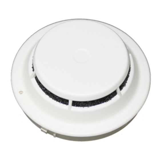
Figure 1
HFPO-11
Do not locate the detectors next to an oil burner, kitchen, or
garage where exhaust fumes can trigger an alarm. Other
causes of false alarm are dust accumulation, heavy concen-
trations of steam, heavy pipe or cigar smoke, and certain aero-
sol sprays.
Air Currents
Before a detector can sense a fire, the products of combustion
or smoke must travel from the fire to the detector. This travel
is especially influenced by air currents; therefore, consider air
movement when designing the system. While combustion
products tend to rise, drafts from hallways, air diffusers, fans,
etc., may help or hinder the travel of combustion products to
the detector. When positioning a detector at a particular loca-
tion, give consideration to windows and doors, both open
and closed, to ventilating systems, both in and out of opera-
tion, and to other factors influencing air movement. Do not
install a detector in the air stream of a room air supply dif-
fuser. It is better to position a detector closer to an air return.
The distance that products of combustion or smoke travel
from a fire to the detector is not usually the shortest linear
route. Combustion products or smoke usually rise to the ceil-
ing, then spread out. Average ceiling heights of 8 to 10 feet
do not abnormally affect detector response. High ceilings, lo-
cated in churches, warehouses, auditoriums, etc., do affect
detector response and should be considered.
Special Ceiling Construction Factors
Ceiling obstructions change the natural movement of air and
combustion products. Depending on the direction of smoke
travel, joists and beams can slow the movement of heated air
and smoke, while pockets between them can contain a re-
duced level of smoke. Take obstructions created by girders,
joists, beams, air conditioning ducts, or architectural design into
consideration when determining area protection. Refer to the
Initiating Devices chapter of NFPA Standard 72 for Location
and Spacing requirements for specific types of construction;
e.g. beam, suspended, level, sloped and peaked ceilings.
TEMPERATURE – HUMIDITY – PRESSURE – AIR VELOCITY
The temperature range for the HFPO-11 detector is 32°F (0°C)
to 100°F (38°C). Use the detector in environments where the
humidity does not exceed 93% (non-condensing). Normal
changes of atmospheric pressure do not affect detector sensi-
Siemens Building T T T T T ec
Siemens Building
Siemens Building
Siemens Building
Siemens Building
ec
echnologies
ec
hnologies
hnologies
hnologies
ec
hnologies
Fire S
Fire Safety
Fire S
afety
afety
afety
Fire S
Fire S
afety
Advertisement

Related Manuals for Siemens HFPO-11


Summary of Contents for Siemens HFPO-11
-
Page 1: Installation Instructions
Do not locate the detectors where excessive smoke concen- trations exist under normal conditions, or in areas of prolonged The temperature range for the HFPO-11 detector is 32°F (0°C) high relative humidity where condensation occurs. to 100°F (38°C). Use the detector in environments where the humidity does not exceed 93% (non-condensing). - Page 2 Movement Areas and Control of Smoke Spread. WIRING When installing SIEMENS Model HFPO-11 in existing instal- Detector bases for SIEMENS Model HFPO-11 should be con- lations with an existing duct detector housing, order an nected as shown in Figure 2.
- Page 3 TO NEXT BASE *The relay contacts are shown after System reset, which represents the non-alarm condition. **HFPO-11 is a polarity insensitive detector. Line 1 and Line 2 can be either line of the loop. Figure 2 Installation and Wiring Diagram...
- Page 4 Siemens Building Technologies, Inc. Siemens Building Technologies, Ltd. 8 Fernwood Road 2 Kenview Boulevard Florham Park, New Jersey 07932 Brampton, Ontario L6T 5E4 P/N 315-034800-1...
Need help?
Do you have a question about the HFPO-11 and is the answer not in the manual?
Questions and answers