Table of Contents
Advertisement
Quick Links
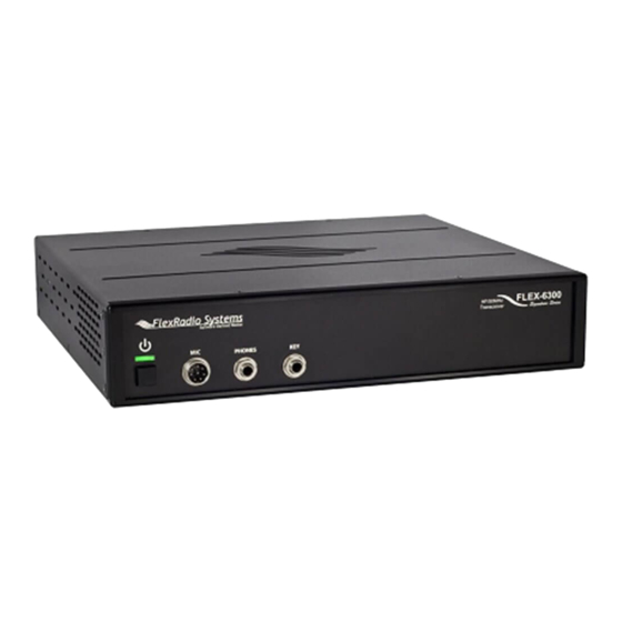
FLEX-6000 SIGNATURE SERIES
FLEX-6000 HARDWARE REFERENCE MANUAL
Version
1.6.21
2/08/2016
Copyright 2015 FlexRadio Systems. All Rights Reserved. FlexRadio Systems is a registered trademark and SmartSDR is a
trademark of FlexRadio Systems. All other brands or names are trademarks of their respective owners.
Advertisement
Table of Contents

Related Manuals for FlexRadio Systems FLEX-6500


Summary of Contents for FlexRadio Systems FLEX-6500
- Page 1 FLEX-6000 SIGNATURE SERIES FLEX-6000 HARDWARE REFERENCE MANUAL Version 1.6.21 2/08/2016 Copyright 2015 FlexRadio Systems. All Rights Reserved. FlexRadio Systems is a registered trademark and SmartSDR is a trademark of FlexRadio Systems. All other brands or names are trademarks of their respective owners.
- Page 2 Miscellaneous edits and 1.5.1 Tim Ellison 10/6/2015 minor corrections Miscellaneous edits and 1.6.17 Tim Ellison 1/11/2016 minor corrections Miscellaneous edits and 1.6.21 Tim Ellison 2/08/2016 minor corrections Page 2 of 48 Copyright 2016 FlexRadio Systems. All Rights Reserved.
-
Page 3: Table Of Contents
6.6.1 Chart for Indicator Color Codes ..............20 6.6.2 Chart for Indicator Color Codes with optional GPSDO Installed ....20 Power Switch ......................21 6.7.1 “Soft Power Control” Multiple Operations ............. 21 Page 3 of 48 Copyright 2016 FlexRadio Systems. All Rights Reserved. - Page 4 PTT Input ........................ 30 7.16 Transverter Port ....................30 7.17 RX ANT-A RF Input ....................30 7.18 RX ANT-A RF Output....................30 7.19 RX ANT-B RF Input (FLEX-6700/6700R only)............ 30 Page 4 of 48 Copyright 2016 FlexRadio Systems. All Rights Reserved.
- Page 5 13 ANTENNA TUNER UNIT (ATU) ..................42 13.1 Specifications ......................42 14 OPTIONAL GPS DISCIPLINED OSCILLATOR (GPSDO) SETUP ......43 14.1 GPSDO Introduction ....................43 14.2 GPS Antenna Placement ..................43 Page 5 of 48 Copyright 2016 FlexRadio Systems. All Rights Reserved.
- Page 6 Frequency Calibration ..................... 45 16 KEY CONTACTS ........................46 16.1 Headquarters / USA ....................46 16.2 Europe ........................46 17 REGULATORY REQUIREMENTS ................... 47 17.1 European Conformity (CE) ..................47 Page 6 of 48 Copyright 2016 FlexRadio Systems. All Rights Reserved.
-
Page 7: Introduction
1.1 WELCOME Thank you for purchasing the FLEX-6000 Signature Series software defined radio (SDR) from FlexRadio Systems. The FLEX-6000 is an example of cutting edge SDR technology using Digital Down Conversion (DDC) for exceptional performance and distortion free reception. Direct Digital Up Conversion (DUC) eliminates analog mixing and IF amplification to minimize spurious output and in-band intermodulation distortion to ensure ultra-clean RF transmission. -
Page 8: Notices To The User
If any interaction or interference with a pacemaker or implanted defibrillator is suspected, STOP transmitting immediately. Page 8 of 48 Copyright 2016 FlexRadio Systems. All Rights Reserved. -
Page 9: Warranty Information
A Return Merchandise Authorization (RMA) number is required before sending in a product for service. An RMA number may be issued by FlexRadio Systems by submitting a HelpDesk support ticket and undergoing troubleshooting procedures with a technical support engineer. -
Page 10: Important Notice - Read Before Operating This Unit
Δ - If any defect, abnormal result, or other observations occur that are not covered by the Quick Start Guide; immediately cease operation and contact the manufacturer or local distributor for operational advice or repair of the unit. Page 10 of 48 Copyright 2016 FlexRadio Systems. All Rights Reserved. -
Page 11: Legal Notices
Third Party Products and Services. The inclusion of a reference to Third Party Products and Services in this documentation does not imply endorsement by FlexRadio Systems of the Third Party Products and Services or the third party in any way. EXCEPT TO THE EXTENT SPECIFICALLY PROHIBITED BY APPLICABLE LAW IN YOUR... - Page 12 THAT IS THE SUBJECT OF THE CLAIM. TO THE MAXIMUM EXTENT PERMITTED BY APPLICABLE LAW IN YOUR JURISDICTION, IN NO EVENT SHALL FLEXRADIO SYSTEMS BE LIABLE FOR ANY TYPE OF DAMAGES RELATED TO THIS DOCUMENTATION OR ITS USE, OR PERFORMANCE OR NON-PERFORMANCE OF...
-
Page 13: Copyright Information
Information in this document is subject to change without notice and does not represent a commitment on the behalf of FlexRadio Systems. No part of this publication may be reproduced, stored in a retrieval system, or transmitted in any form or by any means, electronic, mechanical, photocopying, recording or otherwise, for any purpose other than the purchaser’s personal use, without the prior express written permission of FlexRadio... -
Page 14: Specifications
Weight 10 lbs., 4.53 kgs (FLEX- 10 lbs., 4.5 kgs 13 lbs., 5.9 kgs 6700R) * - Other modes may be available through the addition of third-party waveform plug-ins. Page 14 of 48 Copyright 2016 FlexRadio Systems. All Rights Reserved. -
Page 15: Transmitter
10 kOhm / 2.6Vpp max. 10 kOhm / 2.6Vpp max. 16 Ohm Minimum Load 16 Ohm Minimum Load 16 Ohm Minimum Load Headphone Output @ 21 mW @ 21 mW @ 21 mW Page 15 of 48 Copyright 2016 FlexRadio Systems. All Rights Reserved. -
Page 16: Unpacking And Inspectation
Inspect your FLEX-6000 radio for any physical damage due to rough shipment. Remove the protective cover from the front display. 5.2.3 Included Accessories One (1) FLEX-6000 Signature Series Unit (FLEX-6300, FLEX-6500, FLEX-6700 or FLEX- 6700R) One (1) FHM-1 Microphone (optional for EU countries) (NA to FLEX-6700R) ... -
Page 17: Additional Items Not Included But Required
It is helpful to take digital pictures of the damage to assist in resolving the issue with the shipper. See the CONTACT US web page FlexRadio contact information. You can always open a HelpDesk Ticket at https://helpdesk.flexradio.com Page 17 of 48 Copyright 2016 FlexRadio Systems. All Rights Reserved. -
Page 18: Front Panel Controls And Connections
FLEX-6000 Signature Series – FLEX-6000 Hardware Reference Manual 6 FRONT PANEL CONTROLS AND CONNECTIONS Page 18 of 48 Copyright 2016 FlexRadio Systems. All Rights Reserved. -
Page 19: Microphone Jack
For a straight key or a keyer output, connect to the tip and leave the ring floating. The common is connected to the sleeve. (Note: 3.3VC Max input.) Page 19 of 48 Copyright 2016 FlexRadio Systems. All Rights Reserved. -
Page 20: Multi-Function Display
6.6.2 Chart for Indicator Color Codes with optional GPSDO Installed Note: These additional LED color codes only applies to the FLEX-6700, FLEX-6700R and FLEX-6500 with the optional GPSDO installed. SOLID AMBER: Radio is powered off, GPSDO is powered for stability... -
Page 21: Power Switch
With the radio powered off, press and hold down the power button for approximately 5 seconds until the Power LED flashes white, then release the power button. Allow the radio to continue booting normally. Page 21 of 48 Copyright 2016 FlexRadio Systems. All Rights Reserved. -
Page 22: Rear Panel Connections
FLEX-6000 Signature Series – FLEX-6000 Hardware Reference Manual 7 REAR PANEL CONNECTIONS Page 22 of 48 Copyright 2016 FlexRadio Systems. All Rights Reserved. -
Page 23: Dc Power Input
I - For best results, select a linear or switching power supply that is well regulated and free of internally generated noise. “Birdies” generated by a poorly filtered supply can often appear as signals in the SmartSDR Panadapter display. Page 23 of 48 Copyright 2016 FlexRadio Systems. All Rights Reserved. -
Page 24: Power Pole 30 Amp
Sleeve is common. The audio level is a nominal standard consumer (-10 dBV) line level. Do not use a mono or TS connector that grounds the “ring” portion of the connector. Page 24 of 48 Copyright 2016 FlexRadio Systems. All Rights Reserved. -
Page 25: Accessory Connector
On the FLEX-6300, pin 5 is not enabled and is reserved for future use. 7.4.6 Pin 5, Pin 6, Pin 7, Pin 8 and Pin 10: GROUND These pins are all connected to chassis ground o the FLEX-6700 and FLEX-6500. Pin 5 is not a chassis ground for the FLEX-6300 (see above) Page 25 of 48 Copyright 2016 FlexRadio Systems. -
Page 26: Pin 9: +5Vdc
The radio software samples the external clock input first, then the optional GPSDO (if present), then the internal oscillator (FLEX-6500: TCXO, FLEX-6700/6700R: OCXO). Once an active source is found, the radio software stops looking for any other clock source. If the external source is lost, the radio will look for an active internal oscillator, but it will not look for any other oscillator signal until the radio is powered off and re-started. -
Page 27: Tx Relay Outputs [1,2,3]
Refer to SmartSDR documentation for explanation on how to select which port is active. ! - WARNING: THE FLEX-6500 AND FLEX-6700 ARE CAPABLE OF GENERATING RF POWER LEVELS OF 100 WATTS. HIGH RF LEVELS WILL CAUSE SEVERE RF BURNS. NEVER TOUCH THE TRANSCEIVER ANTENNA PORT, AN EXPOSED COAXIAL CABLE END, OR A CONNECTED ANTENNA WHILE THE RADIO IS IN THE TRANSMIT MODE. -
Page 28: Ethernet Connector
Connector Pin 1 Ground or shield connection Positive phase for balanced Pin 2 mono signals or mic (+) Negative phase for balanced Pin 3 mono signals or mic (-) Page 28 of 48 Copyright 2016 FlexRadio Systems. All Rights Reserved. -
Page 29: Mic Vs. Line Use
MOSFET. Grounding the center pin of this connector will prevent transmit from engaging. Refer to the SmartSDR documentation for information about how the interlock system works and how to determine what is preventing transmit. Page 29 of 48 Copyright 2016 FlexRadio Systems. All Rights Reserved. -
Page 30: Ptt Input
Δ – Please note this input is not protected by the FLEX-6000 ESD circuitry. Any device connected to the RX ANT-B Output is susceptible to possible damage by ESD from an EMP event if the connected device does not have adequate ESD protection circuitry. Page 30 of 48 Copyright 2016 FlexRadio Systems. All Rights Reserved. -
Page 31: Chassis Ground
Antenna connections: 50 Ohm input. Refer to SmartSDR for Windows documentation for explanation on how to select which port is active. 7.27 ATTENTION LABEL “Warning: All input/output connections, including front panel I/O connections, may be static sensitive.” Page 31 of 48 Copyright 2016 FlexRadio Systems. All Rights Reserved. -
Page 32: Installation
100 meters in length before a repeater or switch is required. You should avoid the use of Shielded Twisted Pair (STP) type Ethernet cables. The shield can provide a noise return path that can adversely affect receiver performance. Page 32 of 48 Copyright 2016 FlexRadio Systems. All Rights Reserved. -
Page 33: Direct Pc Connection (Link-Local)
LAN environments, FlexRadio highly recommends a minimum 100Mbit LAN environment. Note that you can easily overload a 10Mbit LAN or LAN component with FLEX-6000 running multiple panadapters and receivers. Page 33 of 48 Copyright 2016 FlexRadio Systems. All Rights Reserved. -
Page 34: Installing Smartsdr
Please refer to the FLEX-6000 Quick Start Guide or the FLEX-6700R Quick Start Guide and SmartSDR Software User’s Guide for information regarding installation, configuration, and operation of your radio with this software. Page 34 of 48 Copyright 2016 FlexRadio Systems. All Rights Reserved. -
Page 35: Fhm-1 Microphone
Set the Tone Switch to the 1 Position: It is best to set the FHM-1 for full range operation and make audio quality adjustments using the software EQ and by adjusting the low and high cut values of the transmit filter. Page 35 of 48 Copyright 2016 FlexRadio Systems. All Rights Reserved. -
Page 36: Transverter Setup
IF port between receive and transmit. The table below shows the compatibility between transverter types and the FLEX-6000 family. Page 36 of 48 Copyright 2016 FlexRadio Systems. All Rights Reserved. -
Page 37: Transmit Power Considerations
While it is technically feasible to use the ANT1 or ANT2 ports for receive, this is not recommended since these ports can produce high-power RF at any time that could damage your transverter. Page 37 of 48 Copyright 2016 FlexRadio Systems. All Rights Reserved. -
Page 38: Ptt Connections
At this time, no band data is provided by the radio and this may provide an effective limit of one transverter at a time. FlexRadio anticipates adding band data in a later release of SmartSDR that would assist remote switching hardware in selecting between multiple transverters. Page 38 of 48 Copyright 2016 FlexRadio Systems. All Rights Reserved. -
Page 39: Digital Mode Setup (Sound Card Interface)
When connecting the FLEX-6000 to a PC sound card, connect one of the FLEX-6000 inputs to the LINE OUT on the sound card and one of the FLEX-6000 outputs to the MIC or LINE IN on the sound card. Page 39 of 48 Copyright 2016 FlexRadio Systems. All Rights Reserved. -
Page 40: Antenna Considerations
The FLEX-6000 Series radios incorporate a unique smart antenna switching matrix to simplify connections from your radio to your station antennas. Below are the signal flow diagrams for the FLEX-6500 and FLEX-6700 transceivers: Page 40 of 48 Copyright 2016 FlexRadio Systems. All Rights Reserved. -
Page 41: Antenna Selection
Using the antenna matrix, you can receive over a wide range, and then use your tuned narrowband antennas for transmitting. Consult the SmartSDR Software User’s Guide for antenna configuration. Page 41 of 48 Copyright 2016 FlexRadio Systems. All Rights Reserved. -
Page 42: Antenna Tuner Unit (Atu)
50 ohm, low SWR load to the power amplifier (PA) for efficient RF power transfer on non-resonant antenna systems. The FLEX-6700 and FLEX-6500 have an integrated ATU as a standard feature whereas the ATU for the FLEX-6300 is a user installable option. -
Page 43: Optional Gps Disciplined Oscillator (Gpsdo) Setup
14 OPTIONAL GPS DISCIPLINED OSCILLATOR (GPSDO) SETUP 14.1 GPSDO INTRODUCTION The FLEX-6700 and FLEX-6500 Signature Series radios have the ability to attain extremely precise frequency control through the use of an optional Global Positioning System Disciplined Oscillator (GPSDO) module. After satellite acquisition and synchronization, the GPSDO is capable of maintaining frequency accuracy to <5.0 x 10... -
Page 44: Gpsdo Lock Sequence And Status Indicators
Earth. This is normal and the radio is fully functional during this process. I - GPSDO self-installation is possible and is covered in a separate installation manual included with the GPSDO OPTION KIT. Page 44 of 48 Copyright 2016 FlexRadio Systems. All Rights Reserved. -
Page 45: Calibration
Please refer to the SmartSDR for Windows Software User’s Guide for detailed frequency calibration instructions. Page 45 of 48 Copyright 2016 FlexRadio Systems. All Rights Reserved. -
Page 46: Key Contacts
Support: https://helpdesk.flexradio.com Community: https://community.flexradio.com 16.2 EUROPE FlexRadio Systems Representative for EU SDR-Funktechnik GmbH Godeke-Michels-Weg 12 D-21762 Otterndorf Germany Phone: (+49) 4751 900501 Fax: (+49) 4751 998569 Email: FlexRadio-EU@t-online.de www.flexradio.com Page 46 of 48 Copyright 2016 FlexRadio Systems. All Rights Reserved. -
Page 47: Regulatory Requirements
Directive on Electronic and electrical equipment (WEEE regulation) and will therefore not be disposed of with household waste. Dispose of the device at your local collection points for electronic equipment! Page 47 of 48 Copyright 2016 FlexRadio Systems. All Rights Reserved. - Page 48 FLEX-6000 Signature Series – FLEX-6000 Hardware Reference Manual European Union Declaration of Conformity FLEX-6000 Amateur Radio Transceiver Series (FLEX-6300 /FLEX-6500 / FLEX-6700 / FLEX- 6700R) According to Radio and Telecommunications Terminal Equipment Directive, (R&TTE) 1999/5/EC - using the Standards: EN 301 489-1 v1.8.1 (2008-04)
Need help?
Do you have a question about the FLEX-6500 and is the answer not in the manual?
Questions and answers
is there a mars module for the 6500 transceiver?