Viessmann Vitodens 200 Operating Instructions And User's Information Manual
Cascade control
Hide thumbs
Also See for Vitodens 200:
- Installation manual ,
- Technical manual (180 pages) ,
- Installation instructions manual (148 pages)
Table of Contents
Advertisement
Quick Links
Operating Instructions and
User's Information Manual
Cascade Control
Outdoor reset control for
up to four gas-fired wall-mounted
Vitodens 200, WB2-44 or -60 boilers
CASCADE CONTROL
IMPORTANT
Read and save these instructions
for future reference.
5285 565 v1.3 11/2003
Certified as a component part
of Viessmann boilers only
Advertisement
Chapters
Table of Contents

Related Manuals for Viessmann Vitodens 200


Summary of Contents for Viessmann Vitodens 200
- Page 1 Operating Instructions and User’s Information Manual Cascade Control Outdoor reset control for up to four gas-fired wall-mounted Vitodens 200, WB2-44 or -60 boilers CASCADE CONTROL IMPORTANT Read and save these instructions for future reference. Certified as a component part of Viessmann boilers only...
- Page 2 Safety, installation and warranty requirements Please ensure that this manual is read and understood before commencing installation. Failure to comply with the issues listed be- low and details printed in this manual can cause product/property damage, severe personal injury, and/or loss of life. Ensure all requirements below are understood and fulfilled (including detailed information found in manual subsections).
-
Page 3: Table Of Contents
General Information Index Content Page General Information ....................................... . . Product information . -
Page 4: Safety
Safety Important regulatory and installation requirements The cascade control must only be used in conjunction with a CSA certified Vitocontrol-S or Vitocontrol-C boiler and system control panel. Power supply Note on connecting external “potential- Working with an open control Install power supply in accordance with free”... -
Page 5: Operation
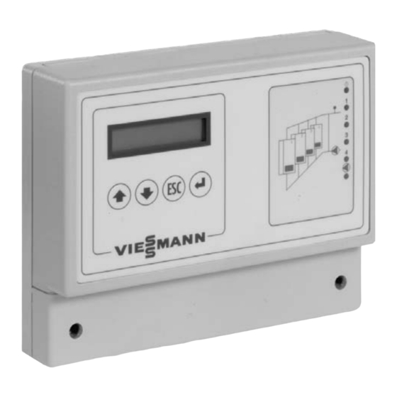
Operation Operating controls and indicators Display Operating buttons System diagram Status indicators Operating buttons Use buttons to display and/or change data in the main and/or sub-menus (depending on configuration and operating level). The function of each button is dependent on the menu item displayed when the button is pressed. Function in normal mode: Scroll up the menu and/or increase the nominal value. -
Page 6: Selection Of Operating Level
Selection of operating level The control unit has three operating levels: Access level 1 Displays simple parameters, such as operating mode and software version. Access level 2 Displays the most important operating details (e.g. actual and set supply temperatures, switching periods and settings such as room temperature setpoint, supply temperature setpoint) and modification of nominal values. - Page 7 Level 1 General function Function 001-A General Press select desired function Date/Time View current date and time. Access Level Return to Access level to alternate menus. Date/Time Operation Data Software type and version.
- Page 8 Level 1 Cascade Control No adjustments Function 001-B Cascade Press select desired function Faults Default display When system no system faults fault detected Flow (Temp) Status Desired (Temp) Fault Operation Data Software Version Time Clock Time Clock Time Clock Normal Operation (no adjustment) Flow (Temp)
- Page 9 Level 2 General Function Function 001-A General Press select desired function Date/Time Current date and time can be viewed and adjusted. Return to Access Level Access level to alternate menus. Date/Time Operation Data View software type and version.
- Page 10 Level 2 Cascade Control Adjustments Function 001-B Cascade Press select desired function Faults Default display When system no system faults fault detected Flow (Temp) Status Desired (Temp) Fault Operation Data Software Version Nominal Values Time Clock Normal operation Time Clock Flow (Temp) Desired...
- Page 11 Level 2 Cascade Control Adjustments Function 001-B Cascade Press select desired function Faults Default display When system no system faults fault detected Flow (Temp) Status Desired (Temp) Fault Operation Data Nominal Values Room Temp (ºC) Normal Time Clock Time Clock (view/ Room Temp (ºC) adjustment possible)
- Page 12 Level 3 General Function Access level Function 001-A General Press select desired function Access Level Access Level 1 or 2 Press once to enter menu option and view Operation Data current Access Level. Press again and ensure current level is Nominal Values flashing.
- Page 13 Level 3 General Function Operation data Function 001-A General Press select desired function Type Version Operation Data VM310 V1.0 Nominal Values Relay Test Return to Operation Data Configuration Date/Time Access Level...
- Page 14 Level 3 General Function Nominal values Function 001-A General Press select desired function Nominal Values Summertime Selection Start Month Relay Test Summertime Selection Month Configuration Return to Nominal Values Date/Time Access Level Operation Data...
- Page 15 Level 3 General Function Relay test Function 001-A General Press select desired function Relay Test Pump (Output) Configuration Backlight Date/Time LED 7 (Compiled Fault LED) Return to Relay Test LED 6 (Pump Indicator) Access Level Operation Data LED 5 (Boiler 4 output indicator) Nominal Values LED 4 (Boiler 3 output...
- Page 16 Level 3 General Function Configuration Function 001-A General Press select desired function Configuration Configuration Yes/No Date/Time Access Level English (Language Section) Return to Configuration Operation Data Summer/Winter Switch Function Yes/No Nominal Values Relay Test...
- Page 17 Level 3 General Function Date/Time Function 001-A General Press select desired function Date/Time dd/mm/yyyy 00:00:00 Press button to change Access Level date or time. Press button to escape from this screen Operation Data Return to Date/Time Nominal Values Relay Test Configuration...
- Page 18 Level 3 Cascade Control Function Configuration menu option Function 001-B Cascade Control Press select desired function Configuration Configure Enter Function Yes/No Outside Sensor Flow Actual Yes/No Desired Operation Data Frost Protection due to Return to Outside Temperature Yes/No Configuration Nominal Values Time Clock Yes/No Holidayprogramme...
- Page 19 Level 3 Cascade Control Function Operation data Function 001-B Cascade Control Press select desired function Operation Data Boiler Sequence 1-2-3-4 Nominal Values Software Version Time Clock Time Clock Normal Operation Holidayprogramme Return to Flow (Temp) Operation Data Desired (Temp) Hour Counters Outside Temperature Impulse Counters (Temp)
- Page 20 Level 3 Cascade Control Function Nominal values Function 001-B Cascade Control Press select desired function Nominal Values Room Temp Normal (Setpt.) Time Clock Room Temp Heating Limit Economy (Setpt.) Differential Holidayprogramme Room Temp Minimum Holiday (Setpt.) Preheat (Min) Hour Counters Return to Outside Temp Maximum...
- Page 21 Level 3 Cascade Control Function Time clock settings Function 001-B Cascade Control Press select desired function Time Clock 06:00-22:00 00:00-00:00 Holidayprogramme 06:00-22:00 00:00-00:00 Hour Counters 06:00-22:00 Impulse Counters 00:00-00:00 Faults 06:00-22:00 Return to 00:00-00:00 Time Clock Configuration 06:00-22:00 00:00-00:00 Flow (Temp) 06:00-22:00 Desired...
- Page 22 Level 3 Cascade Control Function Holidayprogramme settings Function 001-B Cascade Control Press select desired function Holidayprogramme dd/mm/yyyy up to dd/mm/yyyy Hour Counters dd/mm/yyyy Impulse Counters up to dd/mm/yyyy Faults dd/mm/yyyy up to dd/mm/yyyy Configuration dd/mm/yyyy Return to up to dd/mm/yyyy Holidayprogramme Flow (Temp)
- Page 23 Level 3 Cascade Function Hour and impulse counter settings Function 001-B Cascade Control Press select desired function Hour Counter Boiler 1 Boiler 1 Impulse Counter From: dd/mm/yyyy Boiler 2 Faults Boiler 2 From: dd/mm/yyyy Configuration Boiler 3 Boiler 3 dd/mm/yyyy From: Flow (Temp)
- Page 24 Level 3 Cascade Function Faults and fault log Function 001-B Cascade Control Press select desired function Faults Current Date/Time Configuration Fault Log 01 Flow (Temp) Fault Log 10 Desired (Temp) Operation Data Clear Fault Log Return to Yes/No Faults Nominal Values Current Faults Displayed Time Clock Holidayprogramme...
-
Page 25: Initial Start-Up/Configuration
Initial start-up/Configuration The control unit has two setting ranges, which must be configured separately: H General control unit (described in the menu as ”Function 001-A”) for general data, such as date and time H Multiple-boiler control unit (described in the menu as ”Function 001-B”) for the control of a multiple-boiler system in which each boiler is activated based on operating hours and tem- perature. - Page 26 Multiple-boiler control unit Condition: Access level 3 must be selected (see page 6). Select ”Function Cascade control” with , if ”Function Cascade control” is not Function 001-B already displayed; confirm with Cascade control Select ”Configuration” with ; confirm with Configuration Select ”Yes”...
- Page 27 Multiple-boiler control unit (continued) Flue gas header Select ”No”. Flue gas header Boiler sequence change ”Yes”: The start-up sequence is determined once a week based on the operating Auto sequence hours of each boiler. change ”No”: The start-up sequence is permanently set (based on the connection sequence). Pump seizure protection Select ”Yes”...
-
Page 28: Functions
Functions Contents Page Operating status ........................................Displaying the control status . -
Page 29: Operating Status
Operating status You can scan the operating status from the ”Operating data” menu in the function area ”Function Cascade control”. The following operating states may apply: H Normal mode (normal room temperature, e.g. day) H Economy mode (reduced room temperature, e.g. night) H Holiday mode (reduced room temperature, e.g. -
Page 30: Holiday Program
Holiday program Condition: ”Holiday mode Yes” must be configured (see page 26). Eight different holiday periods with start and stop times may be set up in the holiday program. Holiday program (multiple-boiler control unit) The holiday period begins on 16/07/2002 and ends on 15/08/2002. 16-07-2002 up to 15-08-2002 Please note:... -
Page 31: Start-Up Optimization (Early Heat-Up)
Start-up optimization (early heat-up) Start-up optimization ensures that the boiler is heated before the normal mode commences (based on the room and outdoor temperatures). This ensures that the room setpoint temperature is achieved before the normal mode begins. Minimum and maximum temperatures can be set for the heat-up period. -
Page 32: Shutdown During Economy And Holiday Mode
Light Cascade Control heating curve The primary function of the Viessmann Cascade Control is to control the “cascading” or staging of up to four Vitodens 200, WB2-44/60 boilers. It does this by communicating with each individual Vitodens boiler control via the KM-BUS communication module. -
Page 33: Anatomy Of The Cascade Control Heating Curve
Anatomy of the Cascade Control heating curve Setting the starting point and ending point establishes the sloped line to calculate supply temperature based on outdoor temperature. The WWSD point is determined by the Outside Temperature Fixed Point. This point moves left/right on the grid to allow the user to select a specific outdoor temperature. The supply temperature that the Cascade Control calculates when emerging out of WWSD is determined by the Flow Temperature Fixed Point. -
Page 34: Overview Of Adjustments
Overview of settings and adjustments Setting Function Grid movement Range Outside Temperature The outside temperature at which the Left and right 34ºF to 86ºF / Fixed Point control emerges out of WWSD and resumes 1ºC to 30ºC regular operation Flow Temperature Fixed The supply temperature calculated when the Up and down 34ºF to 212ºF /... -
Page 35: Adjustment Of Outside Temperature Fixed Point
Adjustment of outside temperature fixed point Sample graph (with 1.0 curvature) °F °C 176 80 158 70 140 60 122 50 104 40 86 30 68 20 50 10 °C °F Outdoor Temperature Adjustment Outside Temperature Fixed Point ºF / ºC 86 / 30 68 / 20 50 / 10... -
Page 36: Adjustment Of Flow Temperature Fixed Point
Adjustment of flow temperature fixed point Sample graph (with 1.0 curvature) °F °C 176 80 158 70 140 60 122 50 104 40 86 30 68 20 50 10 °C °F Outdoor Temperature Adjustment Outside Temperature Fixed Point ºF / ºC 68 / 20 68 / 20 68 / 20... -
Page 37: Adjustment Of Outside Temperature Climazone
Adjustment of outside temperature climazone Sample graph (with 1.0 curvature) °F °C 176 80 158 70 140 60 122 50 104 40 86 30 68 20 50 10 °C °F Outdoor temperature Adjustment Outside Temperature Fixed Point ºF / ºC 68 / 20 68 / 20 68 / 20... -
Page 38: Adjustment Of Flow Temperature Climazone
Adjustment of flow temperature climazone Sample graph (with 1.0 curvature) °F °C 176 80 158 70 140 60 122 50 104 40 86 30 68 20 50 10 °C °F Outdoor Temperature Adjustment Outside Temperature Fixed Point ºF / ºC 68 / 20 68 / 20 68 / 20... -
Page 39: Adjustment Of Normal Room Temperature
Adjustment of normal room temperature Sample graph (with 1.0 curvature) °F °C 176 80 158 70 140 60 122 50 104 40 86 30 68 20 50 10 °C °F Outdoor Temperature Adjustment Outside Temperature Fixed Point ºF / ºC 68 / 20 68 / 20 68 / 20... -
Page 40: Cascade Curvature
Cascade curvature Unlike the conventional 1.0 curvature and its linear relationship between outdoor and supply temperature, the Cascade Control allows a curvature setting to be programmed. This modifies the linear relationship from a straight line into an arc. The arc runs from the starting (anchor) point to the end point that has been programmed into the control during set-up. -
Page 41: Cascade Combo
End point for curvature. Calculated supply temperature continues based on outdoor temperature shown by dotted line. It is only limited by maximum boiler water temperature. Dotted line shows sloped line with no curvature setting. Maximum temperature limited by Vitodens 200 boiler. -
Page 42: Supply Temperature For External Heat Demand
Nominal value (multiple-boiler control unit) In most cases this value corresponds to the set room temperature in normal mode. Outsidetemp fixed point 20ºC With radiator systems, this value generally corresponds to the low end temperature. Flowtemp A higher setting is recommended for convector heating systems. fixed point 20ºC Design temperature according to the geographical area. -
Page 43: Multiple-Boiler Control Unit
Multiple-boiler control unit The modulating cascade control communicates with the boilers via the KM-BUS interface. It calculates the required supply temperature using an outdoor reset control unit. Start-up and shutdown of individual boilers Depending on the heat demand, individual boilers are started or shut down. A boiler is started up if: H the required heat load is higher than the total output of all boilers which are currently operating. -
Page 44: Automatic Change Of Start-Up Sequence
Automatic change of start-up sequence Condition: ”Auto sequence change Yes” must be configured (see page 27). Once a week the control unit changes the sequence in which the boilers are started up and shut down (based on the operating hours of each boiler). The boiler which has run the fewest hours is the first to be started, fol- lowed by the boiler with the second lowest number of hours run. -
Page 45: Safety Functions
Safety functions Function monitoring with supply temperature reading Proper functioning of the heating system is monitored by comparing the required and the actual supply temper- atures. A fault message is displayed if, within an adjustable period, the supply temperature does not reach the required value less the adjustable tolerated temperature deviation. -
Page 46: Pump Seizure Protection
Pump seizure protection Condition: ”Pump seizure protection Yes” must be configured (see page 27). Between 12:00 and 12:05 hrs daily, the pump will be started to prevent it from seizing up. Hour counters and start-up counters The hours and start-up counters store the number of operating hours and the number of start-ups of the boilers and heating system pumps (if installed), which are regulated by the control unit. - Page 47 Multiple-boiler control unit The system records a fault. Status display Fault Operating details The system records a fault. Faults Faults Example: Flowtemp There is a fault in the supply temperature sensor area. Date and time of the last change in the fault situation. Tu 29-10-2002 08:15:00 The last 10 faults are shown in sequence.
-
Page 48: Technical Specifications
Technical Specifications Sensor resistance table Tem- Resist- Tem- Resist- Tem- Resist- Tem- Resist- perature ance perature ance perature ance perature ance [ºF / ºC] [Ω] [ºF / ºC] [Ω] [ºF / ºC] [Ω] [ºF / ºC] [Ω] 5 / –15 36475 59 / 15 7885... -
Page 52: Quick Reference
+176 +194 +100 +212 +110 +230 Viessmann Manufacturing Company (U.S.) Inc. Viessmann Manufacturing Company Inc. 45 Access Road 750 McMurray Road Warwick, Rhode Island • 02886 • USA Waterloo, Ontario • N2V 2G5 • Canada Tel. (401) 732-0667 • Fax (401) 732-0590 Tel.
Need help?
Do you have a question about the Vitodens 200 and is the answer not in the manual?
Questions and answers