Table of Contents
Advertisement
Advertisement
Table of Contents

Subscribe to Our Youtube Channel
Related Manuals for Matrix Vision mvBlueFOX3


Summary of Contents for Matrix Vision mvBlueFOX3
- Page 1 Technical Manual English - Version 1.55...
-
Page 2: Table Of Contents
Unity license ......... MATRIX VISION GmbH... - Page 3 ........
- Page 4 10.4 Components ..........MATRIX VISION GmbH...
- Page 5 13.2.4 Command-line options ........106 MATRIX VISION GmbH...
- Page 6 14.16.3 mvLUTMapping ........124 14.16.4 LUT support in MATRIX VISION cameras ......124 14.17Sequencer Control...
- Page 7 ........145 20.2 I cannot see the mvBlueFOX3 or I can see it but I cannot use it ....145 20.3 I get an oscillating frame rate .
- Page 8 22.3.6 Working with binning ........237 22.3.7 Minimizing sensor pattern of mvBlueFOX3-1100G ..... . 239 22.4 Working with triggers .
- Page 9 22.10Working with several cameras simultaneously ......295 22.10.1 Creating synchronized acquisitions using timers ..... . . 295 MATRIX VISION GmbH...
- Page 10 23 Appendix A.1 Pregius CMOS specific camera / sensor data 23.1 mvBlueFOX3-2004 (0.4 Mpix [728 x 544]) ......300 23.1.1 Introduction .
- Page 11 23.6.4 Device Feature And Property List ....... 320 23.7 mvBlueFOX3-2051 (5.1 Mpix [2464 x 2056]) ......321 23.7.1 Introduction .
- Page 12 24 Appendix A.2 Starvis CMOS specific camera / sensor data 24.1 mvBlueFOX3-2064 (6.4 Mpix [3096 x 2080]) ......342 24.1.1 Introduction .
- Page 13 25.5.4 Device Feature And Property List ....... 360 25.6 mvBlueFOX3-1031 (3.2 Mpix [2048 x 1536]) ......360 25.6.1 Introduction .
-
Page 14: About This Manual
For example, if you want to know anything about the GUI based applications, then you have to go to the Application Usage (p. 75) book. If you want to know how images are acquired with the mvBlueFOX3, have a look in the respective programming language chapter. - Page 15 • how the log output for "mvIMPACT Acquire" devices is configured and how it works in general, • how to create your own installer packages for Windows and Linux, and • the general mvIMPACT Acquire API documentation. MATRIX VISION GmbH...
-
Page 16: Migration Guide
Just update them to firmware version 2.28.0 or greater. If your applications runs without any problems afterwards you can use the new hardware revisions without any problems as well. For a detailed migration guide for your application please refer to https://www.matrix-vision. com/manuals/SDK_CPP/MigrationGuide.html MATRIX VISION GmbH... -
Page 17: Imprint
MATRIX VISION website. MATRIX VISION cannot guarantee that the data is free of errors or is accurate and complete and, therefore, as- sumes no liability for loss or damage of any kind incurred directly or indirectly through the use of the information of this document. -
Page 18: Introduction
64-bit architectures as well as several mobile platforms including Windows Mobile, iPhone SDK and embedded GTK+. Please refer to the wxWidgets website for detailed license information. The source code of the applications provided by MATRIX VISION GmbH ( http://www.matrix-vision. -
Page 19: Libusbk License
It is provided "as is" without express or implied warranty. See the GNU General Public License for more details. Documents produced by Doxygen are derivative works derived from the input used in their production; they are not affected by this license. MATRIX VISION GmbH... -
Page 20: Sha1 Algorithm
Michael C. Two, Alexei A. Vorontsov or Copyright © 2000-2002 Philip A. Craig 2. Altered source versions must be plainly marked as such, and must not be misrepresented as being the original software. 3. This notice may not be removed or altered from any source distribution. MATRIX VISION GmbH... -
Page 21: Legal Notice
4 Legal notice 4.1 Introduction The firmware running on mvBlueCOUGAR-X, mvBlueCOUGAR-XD and mvBlueFOX3 devices make use of a couple of third party software packages that come with various licenses. This section is meant to list all these packages and to give credit to those whose code helped in the creation of this software. - Page 22 HOLDERS BE LIABLE FOR ANY CLAIM, DAMAGES OR OTHER LIABILITY, WHETHER IN AN ACTION OF CONTRACT, TORT OR OTHERWISE, ARISING FROM, OUT OF OR IN CONNECTION WITH THE SOFTWARE OR THE USE OR OTHER DEALINGS IN THE SOFTWARE. MATRIX VISION GmbH...
-
Page 23: Revisions
Extended Synchronizing cam- era timestamps without IEEE 1588 (p. 287) . 16. October 2017 V1.46 Added new order option for mvBlueFOX3-M2 (p. 32) lensh- older. 22. September 2017 V1.45 mvBlueFOX3-2064 (6.4 Mpix Firmware: 2.24.975.0 [3096 x 2080]) (p. 342) supports triggering . - Page 24 15. December 2016 V1.31 Added Micro-Manger in Driver Firmware: 2.15.578.0 concept (p. 34). 17. November 2016 V1.29 Added information about the cooling area of mvBlueFOX3- M2xxx-1111. 26. October 2016 V1.28 Updated sensor characteristics. 23. August 2016 V1.27 Extended use case Using the Firmware: 2.12.406.0...
- Page 25 V1.09 Added Windows 10 support. 31. July 2015 V1.08 Added dimensional drawing of mvBlueFOX3-IO NC (p. 57). Added USB performance im- provements For Odroid-U2 / - U3 Users (p. 46) and For Rasp- berry Pi Users (p. 46). 28. July 2015 V1.07...
- Page 26 [1600 x 1200]) (p. 354) and mvBlueFOX3-1020a (1.9 Mpix [1600 x 1200]) (p. 357). 25. March 2015 V0.52b Upgraded frame rate calcula- tor of mvBlueFOX3-2024 (2. 4 Mpix [1936 x 1216]) (p. 307). Added chapter Accessing log 11. March 2015 V0.51b files (p. 93).
- Page 27 V0.44b Corrected use case Creating synchronized acquisitions using timers (p. 295) Added additional board for mvBlueFOX3-M to Acces- sories for the mvBlueFOX3 (p. 33). 11. December 2014 V0.43b Corrected pixel clock value of sensor mvBlueFOX3-1012b (1.2 Mpix [1280 x 960]) (p. 346) (66 MHz).
- Page 28 05. June 2014 V0.29b Update chapter Using linescan mode (p. 200). 02. June 2014 V0.28b Removed global reset release mode from mvBlueFOX3-1031 (3.2 Mpix [2048 1536]) (p. 360). 27. May 2014 V0.27b Added use case Reducing noise by frame averaging (p.
- Page 29 Added Image data flow (p. 65). 06 Aug. 2013 V0.7b Added troubleshooting I cannot see the chapter: mvBlueFOX3 or I can see it but I cannot use it (p. 145). Added information about Status / Power LED (p. 63). 27 May 2013 V0.6b Updated mvBlueFOX3-1100 (11 Mpix [3856 x 2764]) (p.
-
Page 30: Graphic Symbols
In the context of the applicable statutory regulations, we shall accept no liability for direct damage, indirect damage or third-party damage resulting from the acquisition or operation of a MATRIX VISION product. Our liability for intent and gross negligence is unaffected. In any case, the extend of our liability shall be limited to the purchase price. -
Page 31: Important Information
7.1 Important safety instructions • We cannot and do not take any responsibility for the damage caused to you or to any other equipment connected to the mvBlueFOX3. Similarly, warranty will be void, if a damage is caused by not following the manual. -
Page 32: Handling And Cleaning
Additional cooling by e.g. air convection is recommended. 7.2.5 Connectors Confirm the power is off before connecting or disconnecting a signal cable. Grasp connectors by the body, not the attached wires. MATRIX VISION GmbH... -
Page 33: Cleaning
• Do not use benzene, thinner, alcohol, liquid cleaner or spray-type cleaner. 7.2.7 Adjusting the C-mount (mvBlueFOX3-2xxx-1xxx) The mvBlueFOX3-2xxx-1xxx does not support back focus adjustment. However, with the four screw locks at the front of the lens holder, it is possible to rotate the C-mount ring. -
Page 34: Adjusting The C-Mount (Mvbluefox3-2Xxx-2Xxx)
7.2.8 Adjusting the C-mount (mvBlueFOX3-2xxx-2xxx) The mvBlueFOX3-2xxx-2xxx cameras allow a precise adjustment of the back focus of the C-mount by means of a back focus ring which is threaded into the C-mount and is secured by a lock nut ring which itself is secured by two screws. - Page 35 7.3 European Union Declaration of Conformity statement The mvBlueFOX3 is in conformity with all applicable essential requirements necessary for CE marking. It corresponds to the EU EMC guideline 2014/30/EU based on the following harmonized standards Electromagnetic compatibility (EMC) • Interference emission EN 61000-6-3 / 2007 •...
- Page 36 CONTENTS MATRIX VISION GmbH...
- Page 37 7.3 European Union Declaration of Conformity statement MATRIX VISION GmbH...
- Page 38 CONTENTS MATRIX VISION GmbH...
-
Page 39: Legal Notice
7.4 Legal notice 7.4 Legal notice 7.4.1 For customers in the U.S.A. MATRIX VISION GmbH... -
Page 40: For Customers In Canada
This apparatus complies with the Class B limits for radio noise emissions set out in the Radio Interference Regula- tions. 7.4.3 Pour utilisateurs au Canada Cet appareil est conforme aux normes classe B pour bruits radioélectriques, spécifiées dans le Règlement sur le brouillage radioélectrique. MATRIX VISION GmbH... -
Page 41: Introduction
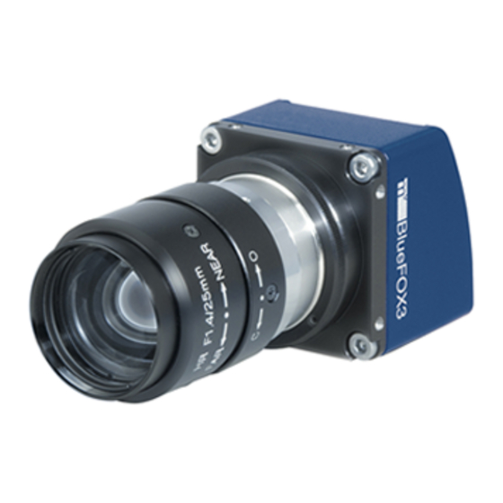
8 Introduction 8 Introduction Figure 1: mvBlueFOX3-1 The mvBlueFOX3 is a compact USB 3.0 camera which is compliant to the brand new vision standard USB3 Vision (p. 170). The mvBlueFOX3 offers • a wide range of CMOS sensors, • high frame rates, •... -
Page 42: Order Code Nomenclatures
Figure 2: Software concept of mvBlueFOX3 As shown in figure 2, for the mvBlueFOX3 the mvIMPACT_Acquire (p. 166) interface is stacked on the USB3 Vision (p. 170) and Genicam (p. 164) layers. The mvIMPACT_Acquire (p. 166) interface internally uses the Gen ICam (p. -
Page 43: Mvbluefox3-M1
2: Color black, no logo - (4): I/O 1: None (standard) 2: With I/O 8.2.2 mvBlueFOX3-M1 The mvBlueFOX3-M1 nomenclature scheme is as follows: mvBlueFOX3-M1(A)(B)(C) - (1)(2)(3)(4) - (A): Sensor model 012b: 1.2 Mpix, 1280 x 960, 1/3" 012d: 1.2 Mpix, 1280 x 960, 1/3"... -
Page 44: Mvbluefox3-M2
CONTENTS - (3): Case 1: standard - (4): I/O 1: standard; if I/O is needed, use separate article: mvBlueFOX3-IO 8.2.3 mvBlueFOX3-M2 The mvBlueFOX3-M2 nomenclature scheme is as follows: mvBlueFOX3-M2(A)(B) - (1)(2)(3)(4) - (A): Sensor model 004: 0.4 Mpix, 728 x 544, 1/2.9", CMOS... -
Page 45: Accessories For The Mvbluefox3
8.3 What's inside and accessories Figure 3: mvBlueFOX3 - scope of supply For this reason, you will need at least • a lens (by default, the mvBlueFOX3 is shipped without lens) and • a USB 3.0 cable to use the mvBlueFOX3. -
Page 46: Quickstart
9 Quickstart 9.1 Driver concept The driver supplied with the MATRIX VISION product represents the port between the programmer and the hardware. The driver concept of MATRIX VISION provides a standardized programming interface to all image processing products (excluding mvBlueLYNX) made by MATRIX VISION GmbH. -
Page 47: Neurocheck Support
For NeuroCheck 6.1 the following devices are supported: Device Additional software needed mvTITAN-G1 mvIMPACT Acquire driver for mvTITAN/mvGAMMA de- vices mvTITAN-CL mvIMPACT Acquire driver for mvTITAN/mvGAMMA de- vices mvGAMMA-CL mvIMPACT Acquire driver for mvTITAN/mvGAMMA de- vices mvHYPERION-CLb mvIMPACT Acquire driver for mvHYPERION devices MATRIX VISION GmbH... -
Page 48: Visionpro Support
Acquire device, it can also be operated from a HALCON environment using the corre- sponding acquisition interface. No additional steps are needed. MATRIX VISION devices that also comply with the GigE Vision standard don't need any software at all, but can also use HALCON's built-in GigE Vision support. -
Page 49: Windows
- your product - Downloads" 9.2.1.1 Hardware MATRIX VISION testet successfully several USB 3.0 extension cards or adapters for PCs and Notebooks. Please have a look here for a current listing: See also http://www.matrix-vision.com/faq-mvbluefox-en.html?show=824 9.2.2 Installing the mvGenTL-Acquire driver By double clicking on •... - Page 50 CONTENTS Figure 2: Driver installation - start window • Now, follow the instructions of installation program and use default settings: Figure 3: Driver installation - select installation folder MATRIX VISION GmbH...
- Page 51 Figure 4: Driver installation - select features • The installation will start and copies the data. At the end, MATRIX VISION's USB3 Vision (p. 170) capture filter driver will be installed. A "Windows Security" dialog will appear.
-
Page 52: Connecting The Camera
GigE Vision devices like the mvBlueCOUGAR-X. During installation, you can select the features you want to install. It is also possible to select "Firmware updates": In this case, the installer will copy the update file "mvBlueFOX3_Update.mvu" into the MATRIX VISION driver installation directory: "[Path: e.g. -
Page 53: Linux
3.5.0 . Please refer to the documentation of your Linux distribution for information on how to update your system's Linux kernel. Following Kernels have been tested and verified by MATRIX VISION for seamless USB3 operation: • Kernel 3.8.0 • Kernel 3.11.0... -
Page 54: Installing The Mvgentl-Acquire Driver
(p. 45) first. To use the mvBlueFOX3 camera within Linux (grab images from it and change its settings), a driver is needed, consisting of several libraries and several configuration files. These files are required during run time. - Page 55 If this argument is not specified, the driver will be placed in the default directory /opt The version argument is entirely optional. If no version is specified, the most recent mvGenTL_Acquire-x86-n.n.n.tgz found in the current directory will be installed. MATRIX VISION GmbH...
-
Page 56: Connecting The Camera
9.3.4 Defining udev rules Most Linux system nowadays use the udev device manager, which is responsible for dynamically managing the tree. In order to be able to use the MATRIX VISION mvBlueFOX3 USB3 Vision (p. 170) camera as non-root /dev user, a special set of rules has to be handed to the udev device manager. -
Page 57: Optimizing Usb Performance
Always keep in mind that it is strongly recommended not to tamper directly with files in the /boot/grub directory! The smallest typing error can render the system not bootable! MATRIX VISION GmbH... - Page 58 4. Reboot the Odroid-XU3 board. 9.3.5.2 For Odroid-U2 / -U3 Users Although Odroid-U2 and Odroid-U3 do not have a USB 3.0 port, you can use the mvBlueFOX3 cameras with the USB 2.0. Jusst adapt the following settings: 1. Locate the file boot.scr...
- Page 59 3. Install the mvGenTL_Acquire driver. Now, the camera should work. Note If you could not find the mvBlueFOX3 driver, you would add the current user to the plugdev group: sudo usermod -a -G plugdev ubuntu 9.3.5.5 For NVIDIA Jetson TX1/TX2 Users To use the camera following adaptions are necessary in the standard configuration of the NVIDIA Jetson TX1/TX2...
-
Page 60: Relationship Between Driver, Firmware, Fpga File And User Settings
CONTENTS 9.4 Relationship between driver, firmware, FPGA file and user settings To operate a GenICam (p. 164) based device like mvBlueFOX3 apart from the physical hardware itself 2 pieces of software are needed: • A firmware running on the device. This firmware consists of –... - Page 61 SDK such as mvDeviceConfigure (p. 101) or by reading the value of the property Device/ FirmwareVersion DeviceControl/DeviceFirmwareVersion using the API • The current FPGA file version used by the device can be obtained by reading the value of the property DeviceControl/mvDeviceFPGAVersion MATRIX VISION GmbH...
- Page 62 Both methods can be used to pre-configure a device. Using the first method, the state of the features will travel with the physical device, using the mvIMPACT Acquire settings, feature states can be copied from host to host as a file. MATRIX VISION GmbH...
-
Page 63: Settings Behaviour During Startup
'VirtualDevice' and there is a setting exclusively for this device storing a product specific setting now will automatically delete the setting for 'VD000001'. Otherwise a product specific setting would never be loaded as a device specific setting will always be found first. MATRIX VISION GmbH... - Page 64 One version of the tool will always be delivered in source so it can be used as a reference to find out how to get the desired information from the device driver. MATRIX VISION GmbH...
-
Page 65: Technical Data
39 x 39 x 24 mm Lens protrusion C-Mount CS-Mount 12.5 mm 7.5 mm C-Mount CS-Mount 17.5 mm (in air) 12.5 mm (in air) 10.1.1.1 Mounting holes On the bottomside, the mvBlueFOX3 provides integrated tripod mounting holes. Figure 2: mvBlueFOX3 mounting holes MATRIX VISION GmbH... -
Page 66: Standard Model -2Xxx
Figure 3: Dimensional drawing of tripod adapter 10.1.2 Standard model -2xxx 10.1.2.1 Option -1xxx (lensholder without back focus adjustment) Figure 4: mvBlueFOX3-2xxx-1xxx dimensions and connectors mvBlueFOX3-2xxx-1xxx Size of body (w x h x l) 40 x 40 x 50.9 mm Lens protrusion 10.7 mm with 1"... - Page 67 10.1 Dimensions Figure 5: mvBlueFOX3-2xxx-1xxx mounting holes 10.1.2.2 Option -2xxx (lensholder with back focus adjustment) Figure 6: mvBlueFOX3-2xxx-2xxx dimensions and connectors mvBlueFOX3-2xxx-2xxx Size of body (w x h x l) 39.8 x 39.8 x 37.7 mm Lens protrusion C-Mount CS-Mount...
-
Page 68: Model Without Housing (-M1)
Figure 7: mvBlueFOX3-2xxx-2xxx mounting holes 10.1.3 Model without housing (-M1) Warning In combination with the connectors, the mechanical stress needs to be limited. Figure 8: mvBlueFOX3-M dimensions and connectors Figure 9: mvBlueFOX3-M1xxx-2xxx with S-Mount lensholder BF3-LH-SMNT 13 MATRIX VISION GmbH... - Page 69 I/O board on the back of the sensor board. Then the I/O board connector will point to the opposite direction as the sensor. Figure 11: mvBlueFOX3-M connected I/O board The pinning of the mvBlueFOX3-I/O is described in the chapter Circular connector male (Power / Digital I/O) (p. 60). MATRIX VISION GmbH...
-
Page 70: Model Without Housing (-M2)
CONTENTS Note There is also a version of the I/O board without connector as "mvBlueFOX3-IO NC" (NC = not connected). The pinning is provided in the figure: Figure 12: mvBlueFOX3-M dimensions of additional I/O board without connector. 10.1.4 Model without housing (-M2) Warning In combination with the connectors, the mechanical stress needs to be limited. - Page 71 10.1 Dimensions Figure 14: mvBlueFOX3-M2xxx-495x dimensions and connectors Warning Please pay attention to the Important safety notes (p. 19) when operating the mvBlueFOX3-M2 without the heat sink backplate. 10.1.4.2 C-mount lensholder and heat sink backplate option (-6151) The heat sink backplate is connected to the GND potential of the camera's power. The connection itself takes place via the fixing points.
-
Page 72: Camera Interfaces
Main shield Connector (camera side): SAMWOO SNH-10-12 (RPCB) or equivalent Plug (matching cable plug): Hirose HR10A-10P-12S (01) or equivalent 10.2.1.1 Pinning of KS-BCX-HR12 Pin. CON 1 mvBlueFOX3-1xxx Signal CON 1 mvBlueFOX3-2xxx Signal CON 2 cutted cable Color GND (for VDC) black... -
Page 73: Characteristics Of The Digital Inputs
Color assignment following international code for UL wiring. 10.2.1.2 Power Supply The mvBlueFOX3 is bus powered. Anyway, it is possible to power the mvBlueFOX3-2 externally with following specs: • Input voltage range: – 12 .. 24V DC (typical) –... -
Page 74: Characteristics Of The Digital Outputs
+3 to +24V (max. 30V) Low level 0V (min. -30V) to +0.7V Threshold 2V +- 1V (Low – High / High – Low) Figure 19: DigIn mvBlueFOX3 10.2.2.2 Switching characteristics Characteristics Symbol Test conditions Typ. Unit Minimum trigger pulse width Turn-On time... -
Page 75: Status / Power Led
1. Off No power or no bootloader found. 2. Red Bootloader was recognized and FPGA is booting-up or device is in standby mode. 3. Green mvBlueFOX3 is running. 4. Green blink mvBlueFOX3 is busy (e.g. file upload). MATRIX VISION GmbH... -
Page 76: Standard Model -2Xxx
4. Green mvBlueFOX3 is streaming images. 5. Yellow blink mvBlueFOX3 is busy (e.g. file upload). 6. White blink Waiting for USB connection (external power is connected) 7. Red Error or if you put the device into standby 10.4 Components... -
Page 77: Sensor Overview
The following block diagrams show the data flow of the image data after being read from the sensor chip in the camera. Figure 1: Block diagram 11.2 Output sequence of color sensors (RGB Bayer) Figure 2: Output sequence of RAW data MATRIX VISION GmbH... -
Page 78: Cmos Sensors
• Erase, exposure and readout 11.3.1.2.1 Trigger Snapshot mode starts with a trigger. This can be either a hardware or a software signal. The CMOS sensors used in mvBlueFOX3 cameras support the following trigger modes: Description Setting in GenICam Free running, no external trigger signal needed (for- "TriggerSelector = FrameStart"... - Page 79 The first image will start with the low-high edge of the signal. The integration time of the exposure register will be used. – OnLowLevel: The first image will start with the high-low edge of the signal. MATRIX VISION GmbH...
-
Page 80: Models
40.2 45.1 40.3 40.2 40.3 40.1 40.2 40.2 40.2 40.2 [dB] 74.2 / 71.4 / 73.4 / 73 / 71.1 / 71.3 / 71.2 / 71.3 / 71.2 / 70.9 / (nor- mal / (p. 263)) [dB] MATRIX VISION GmbH... - Page 81 (p. 167) Linescan mode High color pro- duc- tivity (for color ver- sion) Many trig- modes (free- running, Power approx. approx. approx. approx. approx. approx. approx. approx. approx. approx. approx. approx. con- 3.35 sump- tion (since 146) MATRIX VISION GmbH...
- Page 82 Many trigger modes (free-running, SW, HW) Power consumption (since FW 2.5.146) [W] approx. tbd More specific data mvBlueFOX3-2064 (6.4 Mpix [3096 x 2080]) (p. 342) Measured accord. to EMVA1288 with gray scale version of the camera 11.3.2.3 Aptina, CMOSIS, e2v Sensors 1.2 Mpix...
- Page 83 X / X X / X X / X X / X Pipelined global shut- trigger mode (p. 167) Linescan available available available mode (p. 353) (p. 356) (p. 359) High color repro- ductivity (for color version) MATRIX VISION GmbH...
-
Page 84: Supported Image Formats
YUV422_YUYVPacked YUV444Packed See also For more details about the image formats, please have a look at the enums "TImageDestinationPixel Format" and "TImageBufferPixelFormat" in the C++ developers section. An example application about the pixel formats is also available MATRIX VISION GmbH... -
Page 85: Filters And Lenses
12.2 Cold mirror filter 12 Filters and Lenses MATRIX VISION offers several filters for the mvBlueFOX3camera. The hot mirror filter (p. 73) is part of the standard delivery condition. 12.1 Hot mirror filter The hot mirror filter has great transmission in the visible spectrum and blocks out a significant portion of the IR energy. -
Page 86: Glass Filter
Surface quality polished on both sides P4 Surface irregularity 5/3x0.06 on both sides 12.4 Lenses MATRIX VISION offers a high-quality selection of lenses. If you have questions about our accessories, please contact our sales team: info@matrix-vision.com MATRIX VISION GmbH... -
Page 87: Application Usage
13.1 wxPropView wxPropView (p. 75) is an interactive GUI tool to acquire images and to configure the device and to display and modify the device properties of MATRIX VISION GmbH hardware. After the installation you can find wxPropView (p. 75) •... - Page 88 • a host (PC) based sensor specific "Color Correction Matrix" and use the respective "sRGB display matrix". These settings will also be applied whenever the "Color Preset" button is pressed. It is herewith assumed that color camera image is optimized for best human visual feedback. MATRIX VISION GmbH...
- Page 89 Use OK to use the values and settings of the Quick Setup Wizard and go back to the tree mode of wxPropView. Use Cancel to discard the Quick Setup Wizard values and settings and go back to wxPropView and use the former (or default) settings. MATRIX VISION GmbH...
- Page 90 – Europe: 50 Hz; Set frame rate to 100, 50, 25 12.5 fps or appropriate. – In countries with 60 Hz use 120, 60, 30 or 15. . . accordingly. 13.1.1.2 First View of wxPropView wxPropView (p. 75) consists of several areas: Figure 2:wxPropView started MATRIX VISION GmbH...
- Page 91 (settings or parameters) (according to the "interface layout") accessible by the user. Note Please have a look at the troubleshooting chapter if you neither see the mvBlueFOX3 nor cannot use it (p. 145). You've also got the possibility to set your "User Experience". According to the chosen experience, the level of visibility is different: •...
- Page 92 When the device has been opened successfully, the remaining buttons of the dialog will be enabled: Note Following screenshots are representative and where made using a mvBlueFOX3 camera as the capturing device. For color sensors, it is recommended to perform a white balance (p. 96) calibration before acquiring images. This will improve the quality of the resulting images significantly.
- Page 93 • click the "Acquire" button. Note The techniques behind the image acquisition can be found in the developers sections. Figure 4: wxPropView - First image Three different acquisition modes are available: • Continuous ("Live Mode") • MultiFrame ("Number of Single Snaps") MATRIX VISION GmbH...
- Page 94 If you switched on the request info overlay (righ-click on the display area and select the entry to activate this feature), these information will be displayed on the image, too. With the timestamp you can see the interval of the single frames in microseconds. MATRIX VISION GmbH...
- Page 95 Modified properties (even if the value is the same as the default) will be displayed in black. Figure 6:wxPropView - Storing settings MATRIX VISION GmbH...
- Page 96 ). Properties with no streamable attribute set, will be silently ignored when saving, which means they will not be saved in the XML file. For MATRIX VISION GenICam cameras, starting with firmware version 1.6.414 the streamable attribute is set for all the necessary properties.
- Page 97 • right click on the name of the property and • select "Restore Default". To restore the default value for a complete list (which might include sub-lists) • right click on the name of a list and • select "Restore Default". MATRIX VISION GmbH...
- Page 98 Also the user might want to set all (or a certain range of) values for properties that store multiple values with a single operation. If supported by the property, this can also be achieved by right clicking on the PARENT grid element. If the property allows this modification the pop up menu will again contain additional entries: MATRIX VISION GmbH...
- Page 99 It's possible to either set all (or a range of) elements of the property to a certain value OR to define a value range, that then will be applied to the range of property elements selected by the user. The following example will explain how this works: MATRIX VISION GmbH...
- Page 100 )". This will specific a function returning an integer value and expecting a string and an integer as input parameters. To execute a method object • right click on the name of a method and • select "Execute" from the popup menu: MATRIX VISION GmbH...
- Page 101 CSV style thus can be pasted directly into tools like Open Office™ or Microsoft® Office™. Just • right-click on the specific analysis grid when in numerical display mode and • select "Copy grid to clipboard" from the pop up menu. Figure 13:wxPropView - Copying grid data to the clipboard MATRIX VISION GmbH...
- Page 102 "dcy" . In this step by step setup wxPropView (p. 75) has been started like this from the command line: wxPropView dcx=1 dcy=2 This will result in 1 display in horizontal direction and 2 in vertical direction. MATRIX VISION GmbH...
- Page 103 (p. 75) shows snapped or live images in the display area of the GUI. The area, however, shows the most significant bits (msb) of the image in the 8 bit display. The following image shows how a mid-grey 12 bit pixel of an image is displayed with 8 bit. Additionally, two shifts are shown. MATRIX VISION GmbH...
- Page 104 View". While the first (default) view will display the device drivers feature tree in a way that might be suitable for most users of a GUI application it might present the features in a slightly different order as they actually are implemented MATRIX VISION GmbH...
- Page 105 Figure 17:Developers View 13.1.1.12 Accessing log files Since mvIMPACT Acquire 2.11.9 Using Windows, it is possible to access the log files generated by MATRIX VISION via the Help menu. Sending us the log files will speed up support cases. MATRIX VISION GmbH...
-
Page 106: How To Configure A Device
As described above, after the device has been initialized successfully in the "Grid" area of the GUI the available "interface layout" properties are displayed in a hierarchy tree. GenICam (p. 164) is the default interface layout of the mvBlueFOX3 and we recommend to use it! wxPropView - Configuring a device: https://www.matrix-vision.com/tl_files/mv11/trainings/wxPropView/wx... - Page 107 • When an application shall be able to work with every MATRIX VISION device and every GigE Vision (p. 165) and GenICam (p. 164) compliant device both approaches make sense however a mixture between the 2 worlds can't be avoided.
- Page 108 Standard Feature Naming Convention of GenICam properties (p. 168) 13.1.2.2 White balance of a camera device (color version) Start the wxPropView (p. 75) and initialize the device by clicking "Use" and start a "Continuous" acquisition. Figure 21: wxPropView - Continuous mode MATRIX VISION GmbH...
- Page 109 The "White Balance Control" can be found in "Setting - Base - Camera - GenICam - Analog Control - Balance White Auto". Just select "Continuous" and you will get a white balanced image. Figure 22: wxPropView - Selecting WhiteBalance profile MATRIX VISION GmbH...
- Page 110 (Analysis tabs). Whenever an event is send by the device that updates one of the properties a callback has been attached to, the output window will print a message with some information about the detected change. MATRIX VISION GmbH...
- Page 111 13.1.2.5 Saving user settings in the non-volatile flash memory The mvBlueFOX3 camera offers the possibility, to save up to 4 user sets in the camera's flash memory directly. This means that all camera specific settings you've adjusted via wxPropView (p. 75) can be saved in a non-volatile memory.
-
Page 112: Command-Line Options
Example (will start the live acquisition): live=1 13.1.3.1 Sample (Windows) wxPropView.exe d= * fulltree=1 qsw=0 This will start the first available device, will hide the Quick Setup Wizard, and will display the complete property tree. MATRIX VISION GmbH... -
Page 113: Mvdeviceconfigure
13.2 mvDeviceConfigure 13.2 mvDeviceConfigure mvDeviceConfigure (p. 101) is an interactive GUI tool to configure MATRIX VISION devices. It shows all connected devices. With mvDeviceConfigure (p. 101) it is possible e.g. • to check, if the camera is accessible on host PC, •... - Page 114 13.2.1.2 Step 2: Start firmware update • You have to close applications using the device and click Figure 27: mvDeviceConfigure - Close all applications • You have to select the update file – mvBlueFOX3: mvBlueFOX3_Update.mvu Figure 28: mvDeviceConfigure - Select firmware file Warning All current camera settings will be lost when updating the firmware.
- Page 115 (versionInfo.txt and/or the manual to see if the update will fix your problem). The firmware update takes several minutes and during this time the application will not respond! MATRIX VISION GmbH...
-
Page 116: Preserving Userset Settings When Updating The Firmware
This time is enough to cause image error counts! See also More informations about ACPI: http://en.wikipedia.org/wiki/Advanced_Configuration _and_Power_Interface To disable the power management on the processor level (so-called "C states"), you can use mvDevice Configure: MATRIX VISION GmbH... - Page 117 1. Start mvDeviceConfigure. 2. Go to tab and unselect "Settings" "CPU Idle States Enabled" Figure 33: mvDeviceConfigure - Settings The sleep states can also be enabled or disabled from a script by calling mvDeviceConfigure like this: mvDeviceConfigure.exe set_processor_idle_states=1 quit MATRIX VISION GmbH...
-
Page 118: Command-Line Options
(if no suitable device is found) a device with a matching product string. The number of commands that can be passed to the application is not limited. MATRIX VISION GmbH... - Page 119 This will update the firmware of 2 mvBlueFOX cameras. mvDeviceConfigure ipv4_mask=169.254. * ;192.168.100 * update_fw=GX * This will update the firmware of all mvBlueCOUGAR-X devices with a valid IPv4 address that starts with '169.254.' or '192.168.100.'. MATRIX VISION GmbH...
-
Page 120: Genicam And Advanced Features
As you can see, there are some controls with and without the prefix "mv". • "mv" prefix features are unique non-standard features developed by MATRIX VISION. • Without "mv" are standard features as known from the Standard Feature Naming Convention of GenICam properties (p. -
Page 121: Device Control
Link. DeviceTemperature deviceTemperature Device temperature. etc. related to the device and its sensor. MATRIX VISION offers also some information properties about the • FPGA – mvDeviceFPGAVersion • and the image sensor – mvDeviceSensorName – mvDeviceSensorColorMode 14.3 Image Format Control The "Image Format Control"... -
Page 122: Acquisition Control
• mvBayerRaw (the Bayer mosaic raw image) • mvFFCImage (the flat-field correction image (p. 213) ) Additionally, MATRIX VISION offers numerous additional features like: • mvMultiAreaMode which can be used to define multiple AOIs (Areas of Interests) in one image. - Page 123 +/-0.005 fps at 200 fps. This is achieved using frames with a length difference of up to 1 us. Please check in the sensor summary (p. 65) if this fea- ture exists for the requested sen- sor. MATRIX VISION GmbH...
- Page 124 ExposureMode is Timed. etc. related to the image acquisition, including the triggering mode. Additionally, MATRIX VISION offers numerous additional features like: • mvShutterMode which selects the shutter mode of the CMOS sensors like rolling shutter or global shutter. • mvDefectivePixelEnable which activates the sensor's defective pixel correction.
- Page 125 AutoControl AOI used for Auto Gain Control (AGC), Auto Exposure Control (AEC) and Auto White Balance (AWB). • mvAcquisitionMemoryMode MATRIX VISION offers three additional acquisition modes which use the internal memory of the mvBlueC OUGAR-X: – mvRecord (p. 176) which is used to store frames in memory.
-
Page 126: Counter And Timer Control
Exposure Auto 14.5 Counter And Timer Control The "Counter And Timer Control" is a powerful feature which MATRIX VISION customers already know under the name Hardware Real-Time Controller (HRTC). mvBlueCOUGAR-X provides: • 4 counters for counting events or external signals (compare number of triggers vs. number of frames; over- trigger) and •... -
Page 127: Analog Control
CT Acquire (p. 166)) GainSelector gainSelector Selects which gain is controlled by the various gain features. Gain[GainSelector] gain Controls the selected gain as an absolute physical value [in dB]. GainAuto[GainSelector] gainAuto Sets the automatic gain control (AGC) mode. MATRIX VISION GmbH... - Page 128 Additionally, MATRIX VISION offers: • mvBalanceWhiteAuto functions and • mvGainAuto functions. In wxPropView (p. 75) just select in "Gain Auto" (AGC) "Continuous". Afterwards, you have the possibility to set...
-
Page 129: Mv Logic Gate Control
Represents the value of the se- lected Gain factor or Offset inside the transformation matrix. ColorTransformationValueSelector colorTransformationValueSelector Selects the gain factor or Offset of the Transformation matrix to ac- cess in the selected color transfor- mation module. MATRIX VISION GmbH... -
Page 130: Mv Flat Field Correction Control
Starts the calibration of the flat field correction. related to control the devices Flat Field Correction parameters. The use case Flat-Field Correction (p. 213) shows how this control can be used. 14.10 Event Control The "Event Control" contains features like MATRIX VISION GmbH... -
Page 131: Chunk Data Control
The "Chunk Data Control" contains features like Feature name (acc. to SFNC Property name (acc. to mvIMPA Description (p. 168)) CT Acquire (p. 166)) ChunkModeActive chunkModeActive Activates the inclusion of chunk data in the payload of the image. MATRIX VISION GmbH... -
Page 132: File Access Control
file is opened in the device. FileAccessBuffer fileAccessBuffer Defines the intermediate access buffer that allows the exchange. etc. related to the File Access Control that provides all the services necessary for generic file access of a device. MATRIX VISION GmbH... -
Page 133: Mv Serial Interface Control
Input or Output a signal. UserOutputSelector fileOperationExecute Selects which bit of the user output register will be set by UserOutput Value. etc. related to the control of the general input and output pins of the device. Additionally, MATRIX VISION offers: MATRIX VISION GmbH... -
Page 134: Encoder Control
Encoder. Writing to EncoderValue is typically used to set the start value of the position counter. related to the usage if quadrature encoders. The following figure explains the different EncoderOutputModes : Figure 5: EncoderOutputModes MATRIX VISION GmbH... -
Page 135: Lut Control
This saves (approx. 5%) CPU load, works on the fly in the FPGA of camera, is less noisy and there are no missing codes after Gamma stretching. Three read-only registers describe the LUT that is selected using the LUTSelector register: MATRIX VISION GmbH... -
Page 136: Mvluttype
Considering a 10 - 10 bit interpolated LUT with 256 nodes (as usually used in MATRIX VISION cameras), the user defines a 10 bit output value for 256 equidistant nodes beginning at input value 0, 4, 8, 12, 16 and so on. -
Page 137: Sequencer Control
The features which are actually part of a sequencer set are defined by the camera manufacturer. These features can be read by SequencerFeatureSelector and acti- vated by SequencerFeatureEnable[SequencerFeatureSelector]. This configuration is the same for all Sequencer MATRIX VISION GmbH... - Page 138 Enable[SequencerFeature make it active in all the sequencer Selector] sets. SequencerSetSelector sequencerSetSelector Selects the sequencer set to which further settings applies. SequencerSetSave sequencerSetSave Saves the current device state to the selected sequencer set se- lected by SequencerSetSelector. MATRIX VISION GmbH...
- Page 139 SequencerSetStart sequencerSetStart Sets the initial/start sequencer set, which is the first set used within a sequencer. SequencerPath sequencerPathSelector Selects to which branching path Selector[SequencerSetSelector] further path settings apply. SequencerSetNext sequencerSetNext Select the next sequencer set. MATRIX VISION GmbH...
- Page 140 CONTENTS SequencerTriggerSource sequencerTriggerSource Specifies the internal signal or physical input line to use as the sequencer trigger source. Values supported by MATRIX VISION devices are: • Off: Disables the sequencer trigger. • ExposureEnd: Starts with the reception of the ExposureEnd event.
- Page 141 The sequence is configured by a list of parameters sets. Note At the moment, the Sequencer Mode is only available for MATRIX VISION cameras with CCD sensors and Sony's CMOS sensors. Please consult the "Device Feature and Property List"s to get a summary of the actually supported features of each sensor.
-
Page 142: Transport Layer Control
Transport Layer Control. In this section MATRIX VISION provides a bandwidth control feature . You have to select mvGevSCBWControl in the GevStreamChannelSelector. A new property with the same name will appear. Here you can set the maximum bandwidth in KBps. -
Page 143: Mv Frame Average Control (Only With Specific Models)
Feature name (acc. to SFNC Property name (acc. to mvIMPA Description (p. 168)) CT Acquire (p. 166)) mvFrameAverageEnable Enables the frame averaging en- gine. mvFrameAverageSlope The slope in full range of register. related to the frame averaging engine. MATRIX VISION GmbH... -
Page 144: Mv High Dynamic Range Control (Only With Specific Sensor Models)
First HDR exposure in ppm. mvHDRExposure2 Second HDR exposure in ppm. related to the control of the device High Dynamic Range parameters. The use case Adjusting sensor -x02d (-1012d) (p. 263) shows the principle of the HDR. MATRIX VISION GmbH... -
Page 145: C Developers
The description for the mvIMPACT Acquire SDK for C developers is available as a separate file: mvIMPACT_ Acquire_API_C_manual.chm which is • either part of the installed package or • online from https://www.matrix-vision.com Here an online version of the documentation is available as well. MATRIX VISION GmbH... -
Page 146: C++ Developers
The description for the mvIMPACT Acquire SDK for C++ developers is available as a separate file: mvIMPACT_ Acquire_API_CPP_manual.chm which is • either part of the installed package or • online from https://www.matrix-vision.com Here an online version of the documentation is available as well. MATRIX VISION GmbH... -
Page 147: Net Developers
The description for the mvIMPACT Acquire SDK for .NET developers is available as a separate file: mvIMPACT _Acquire_API_NET_manual.chm which is • either part of the installed package or • online from https://www.matrix-vision.com Here an online version of the documentation is available as well. MATRIX VISION GmbH... -
Page 148: Python Developers
'mvIMPACT Acquire for python' for Python versions 2.7 to 3.2: https://www.microsoft.com/en-us/download/details.aspx?id=44266 The use of this compiler packet has been tested by MATRIX VISION and it is is highly recommended. When installing the mvIMPACT Acquire Python API on a target system all files needed for building the actual extension module can be found in /mvIMPACT_Python. -
Page 149: Linux
# If you want to use this module in your code feel free to do so but make sure the ’Common’ folder resides in a sub-folder of your project then from Common import # For systems with NO mvDisplay library support #import ctypes #import Image MATRIX VISION GmbH... - Page 150 #else: img = Image.fromarray(arr, ’RGBA’ if alpha else ’RGB’) pPreviousRequest != None: pPreviousRequest.unlock() pPreviousRequest = pRequest fi.imageRequestSingle() else: print("imageRequestWaitFor failed (" + str(requestNr) + ", " + ImpactAcquireException. getErrorCodeAsString(requestNr) + ")") manuallyStopAcquisitionIfNeeded(pDev, fi) raw_input("Press Enter to continue...") MATRIX VISION GmbH...
- Page 151 The above code uses the Python 3 style print. Because of the line from __future__ import print_function This will also work with Python versions starting with version 2.6. For smaller versions of Python the code needs to be changed! MATRIX VISION GmbH...
-
Page 152: Directshow Interface
19.1.6 ISpecifyPropertyPages 19.2 Logging The DirectShow_acquire logging procedure is equal to the logging of the MATRIX VISION products which uses mvIMPACT Acquire. The log output itself is based on XML. If you want more information about the logging please have a look at the Logging chapter of the respective "mvI MPACT Acquire API"... -
Page 153: Registering And Renaming Devices For Directshow Usage
. I.e. if you have installed the 32 bit version of the VLC Media Player, Virtual Dub, etc., you have to register the MV device with the 32 bit version of mvDeviceConfigure (p. 101) ("C:\Program Files\MATRIX VISION\mvI MPACT Acquire\bin") ! 19.3.1 Registering devices... - Page 154 CONTENTS Figure 2: mvDeviceConfigure - register all devices 3. After a successful registration the column "registered for DirectShow" will display 'yes' for every device and the devices will be registered with a default DirectShow friendly name. MATRIX VISION GmbH...
-
Page 155: Renaming Devices
2. Now, select the device you want to rename, click the right mouse button and select "Set DirectShow friendly name": Figure 4: mvDeviceConfigure - set DirectShow friendly name 3. Then, a dialog will appear. Please enter the new name and confirm it with "OK". MATRIX VISION GmbH... -
Page 156: Make Silent Registration
The following command line options are available an can be passed during the silent registration: EXAMPLES: Register ALL devices that are recognized by mvIMPACT Acquire (this will only register devices which have drivers installed). regsvr32 <path> DirectShow_acquire.ax /s MATRIX VISION GmbH... -
Page 157: Troubleshooting
USB3 Vision (p. 170) device is bound to the system via a driver. Because a device can only be bound to one driver in the system, it could be possible that the mvBlueFOX3 is bound to another USB3 Vision (p. - Page 158 • Open the "Device Manager" from "Control Panel - System - Device Manager" On this system, the mvBlueFOX3 is bound to the driver "NI Acquisition Device" Figure 2: mvBlueFOX3 as a NI Acquisition Device • Right-click the device and select "Update Driver Software..."...
- Page 159 20.2 I cannot see the mvBlueFOX3 or I can see it but I cannot use it Figure 4: Let me pick from a list of device drivers on my computer • Select the MATRIX VISON USB3 Vision driver called "USB3 Vision Device(Bound to MATRIX VISION !GmbH driver using libusbK)"...
-
Page 160: I Get An Oscillating Frame Rate
CONTENTS Figure 6: Driver update was successful • Now, you can see, that the mvBlueFOX3 is bound to the MATRIX VISION driver via libusbK Figure 7: mvBlueFOX3 is bound to the MATRIX VISION driver via libusbK 20.3 I get an oscillating frame rate If your camera supports FrameRateExactness it is possible that you may receive an oscillating frame rate. -
Page 161: Accessing Log Files
4096 Mai 21 15:12 SynchronousCaptureMultipleInputsFLTK drwxr-xr-x 9 user user 4096 Mai 21 15:12 testserial In order that log files are generated, you have to execute your app from the folder, where mvDebugFlags.mvd is located. E.g. if you want to start wxPropView: MATRIX VISION GmbH... -
Page 162: Why Does Updating The Device List Take So Long
GigE Vision in their application, until the device update is finished. For this reason, we upgraded the MATRIX VISION application tools (p. 75) to excluded interfaces or single devices to be scanned or detected. The easiest way to do so is as follows: 1. -
Page 163: Error Code List
-2001 PROPHANDLING_NOT_ This component is not a A property operation for this A_PROPERTY property. component has been called but this component does not reference a property.[-2001] MATRIX VISION GmbH... - Page 164 The caller requested a fea- MENTATION_MISSING mented so far has been re- ture, that hasn't been im- quested. plemented so far. This er- ror code is only provided for compatibility and will be set in very rare cases only.[- 2010] MATRIX VISION GmbH...
- Page 165 [-2012] -2013 PROPHANDLING_PROP The properties translation The properties translation _TRANSLATION_TABLE table has been corrupted. table has been corrupted _CORRUPTED for an unknown reason and can't be used anymore.[- 2013] MATRIX VISION GmbH...
- Page 166 -2019 PROPHANDLING_COMP The specified component [-2019] ONENT_NOT_FOUND could not be found. -2020 PROPHANDLING_LIST_I An invalid list has been refer- [-2020] D_INVALID enced. MATRIX VISION GmbH...
- Page 167 _REGISTERED callback has been registered for this component. -2031 PROPHANDLING_INPUT The user tried to read data [-2031] _BUFFER_TOO_SMALL into a user supplied storage location, but the buffer was too small to accommodate the result. MATRIX VISION GmbH...
- Page 168 ID has been passed to the device man- ager or if the caller tried to close a device which cur- rently isn't initialized.[-2100] -2101 DMR_INIT_FAILED The device manager couldn't This is an internal error.[- be initialized. 2101] MATRIX VISION GmbH...
- Page 169 MATRIX VISION GmbH...
- Page 170 The creation of a setting This can either happen, _FAILED failed. when a setting with the same name as the one the user tried to create already ex- ists or if the system can't al- locate memory for the new setting.[-2114] MATRIX VISION GmbH...
- Page 171 'state' prop- erty should be checked to find out if the device is still present or not. [-2119] -2120 DEV_UNSUPPORTED_P The user tried to get/set a [-2120] ARAMETER parameter, which is not sup- ported by this device. MATRIX VISION GmbH...
- Page 172 -2132 DMR_CAMERA_DESCRI A function call was associ- One possible reason might PTION_INVALID ated with a camera descrip- be, that the camera descrip- tion, that is invalid. tion has been deleted(driver closed?).[-2132] MATRIX VISION GmbH...
- Page 173 2137] -2138 DEV_REQUEST_BUFFE A request has been config- [-2138] R_INVALID ured to use a user supplied buffer, but the buffer pointer associated with the request is invalid. MATRIX VISION GmbH...
- Page 174 AOI.A scan stan- dard has been selected, that is not supported by this device.An invalid scan rate has been selected..This error code will be returned by frame grabbers only.[- 2142] MATRIX VISION GmbH...
- Page 175 [-2145] GINE_BUSY user application attempts to start the acquisition engine at a time, where it is already running. -2199 DMR_LAST_VALID_ERR Defines the last valid error [-2199] OR_CODE code value for device and device manager related er- rors. MATRIX VISION GmbH...
-
Page 176: Glossary
CONTENTS 21 Glossary Application programming interface (API). The standard API for MATRIX VISION products is called mvIMPACT_Acquire (p. 166). Common internet file system (CIFS) replaced Samba in 2006. CIFS It gets rid of NetBIOS packets an introduced Unix features like soft/hard links and allows larger files. - Page 177 For further information please have a look at https://en.wikipedia.org/wiki/GigE_ Vision The MATRIX VISION GigE Vision capture filter driver as well as the socket based acquisition driver and all MATRIX VISION GigE Vision compli- ant devices support resending thus lost data can be detected and in most cases reconstructed.
- Page 178 This driver supplied with MATRIX VISION products represents mvIMPACT Acquire the port between the programmer and the hardware. The driver concept of MATRIX VISION provides a standardized programming interface to all image processing products (excluding standard mvBlueLYNX) made by MATRIX VISION GmbH.
- Page 179 In overlapped trigger mode, you have to keep in mind the following formula interval between two trigger events >= (readout time - exposure time) Sofware development kit (SDK). The standard image processing software library from MARTIX VISION is mvIMPACT. MATRIX VISION GmbH...
- Page 180 1. Start e.g. Konqueror or Explorer. 2. Enter in the address line (e.g.): smb://192.168.19.123 or smb://mvBlueCOUGAR-SDK (Linux) //192.168.19.123 or mvBlueCOUGAR-SDK (Windows) 3. Enter user: mvbc 4. Enter password: mvbc 5. All available folders and devices will be shown. MATRIX VISION GmbH...
- Page 181 2. Configure Session (IP address of mvBlueCOUGAR). 3. Configure Connection (user login root in Data) and click Open. A console will open, where you have to enter "root" as password. After- wards, you will be connected to the mvBlueCOUGAR. MATRIX VISION GmbH...
- Page 182 • point it to the remote system. You won't need a password. Of course, you won't get a very fast live image display via the network with VNC but you should be able to start wxPropView (p. 75) and capture images. MATRIX VISION GmbH...
-
Page 183: Use Cases
files must be repeated for each interface layout. Once the device has been opened the code generator can be accessed by navigating to "System Settings CodeGeneration" Figure 1: wxPropView - Code Generation section MATRIX VISION GmbH... - Page 184 Once a file name has been selected the code generator can be invoked by executing the "int GenerateCode()" method: Figure 2: wxPropView - GenerateCode() method The result of the code generator run will be written into the "LastResult" property afterwards: MATRIX VISION GmbH...
-
Page 185: Using The Result Of The Code Generator In An Application
// XML file may not be compatible thus different interface files should be created here // all code will reside in this inner namespace // namespace MATRIX_VISION_mvBlueIntelligentDevice_1 // namespace DeviceSpecific // namespace acquire // namespace mvIMPACT MATRIX VISION GmbH... -
Page 186: Introducing Acquisition / Recording Possibilities
When working with a using statement the same code can be written like this as well: //----------------------------------------------------------------------------- void fn( Device * pDev ) //----------------------------------------------------------------------------- DeviceControl dc( pDev ); if( dc.timestampLatch.isValid() ) dc.timestampLatch.call(); 22.2 Introducing acquisition / recording possibilities There are several use cases concerning the acquisition / recording possibilities of the camera: MATRIX VISION GmbH... -
Page 187: Acquiring A Number Of Images
The following figure shows, how to set the scenario shown in Figure 1 with wxPropView (p. 75) Figure 2: wxPropView - Setting acquisition of a number of images started by an external signal A rising edge at line 4 will start the acquisition of 20 images. MATRIX VISION GmbH... -
Page 188: Recording Sequences In The Camera
Acquisition Memory Max Frame Count (p. 110) can be increased by reducing the image height. 22.2.3 Recording sequences with pre-trigger 22.2.3.1 What is pre-trigger? With pre-trigger it is possible to record frames before and after a trigger event. MATRIX VISION GmbH... - Page 189 The camera will output the number of pre-trigger frames as fast as possible followed by the frames in live mode as fast as possible until the frame rate is in sync: Figure 2: wxPropView - recorded / output images MATRIX VISION GmbH...
-
Page 190: Creating Acquisition Sequences (Sequencer Control)
Note At the moment, the Sequencer Mode is only available for MATRIX VISION cameras with CCD sensors and Sony's CMOS sensors. Please consult the "Device Feature and Property List"s to get a summary of the actually supported features of each sensor. - Page 191 • Frame 1: 1000 us • Frame 2: 5000 us • Frame 3: 10000 us • Frame 4: 20000 us • Frame 5: 50000 us • Frame 6: 50000 us • Frame 7: 50000 us MATRIX VISION GmbH...
- Page 192 However, wxPropView offers a wizard (p. 185) to define an acquisition sequence in a much easier way. 1. First, switch into the "Configuration Mode": "Sequencer Configuration Mode" = "On". Only then the sequencer on a device can be configured. MATRIX VISION GmbH...
- Page 193 3. Set the "Sequencer Feature Selector" for the duration counter (pink box, figure 4): "Sequencer Feature Selector" = "CounterDuration" and "Sequencer Feature Enable" = "1". 4. Then, each sequencer set must be selected by the "Sequencer Set Selector" (orange box, figure 3): "Sequencer Set Selector" = "0". MATRIX VISION GmbH...
- Page 194 10. Set the following sequencer set with "Sequencer Set Next" and trigger source with "Sequencer Trigger Source" (brown box, figure 4): "Sequencer Set Next" = "0". This will close the loop of sequencer sets by jumping from here back to the MATRIX VISION GmbH...
- Page 195 11. Set the "Exposure Time" (red box, figure 4): "Exposure Time" = "50000". Figure 4: wxPropView - Sequencer set 4 12. Set the "Counter Duration" in "Counter And Timer Control" (red box, figure 5): "Counter Duration" = "5". MATRIX VISION GmbH...
- Page 196 13. Finally, save the "Sequencer Set" (green box, figure 3): "int SequencerSetSave()". 14. Leave the "Configuration Mode" (red box, figure 4: "Sequencer Configuration Mode" = "Off". 15. Activate the "Sequencer Mode" (red box, figure 4): "Sequencer Mode" = "On". Figure 6: wxPropView - "Sequencer Mode" = "On" MATRIX VISION GmbH...
- Page 197 Figure 7: wxPropView - Info Plot shows the exposure times 22.2.4.3 Using the Sequencer Control wizard Since mvIMPACT Acquire 2.18.0 wxPropView (p. 75) offers a wizard for the Sequencer Control (p. 125) usage: Figure 8: wxPropView - Wizard button MATRIX VISION GmbH...
- Page 198 "Path 1" ("SequencePathSelector = 1") will jump to "Set 1" after it is activated via a "RisingEdge" ("Sequencer TriggerActivation = RisingEdge") signal at "UserOutput0" ("SequencerTriggerSource = 0"). "UserOutput0" can be connected, for example, to one of the digital input lines of the camera: MATRIX VISION GmbH...
- Page 199 First the sequencer has to be configured. #include <mvIMPACT_CPP/mvIMPACT_acquire_GenICam.h> GenICam::SequencerControl sc = GenICam::SequencerControl( pDev ); GenICam::AcquisitionControl ac = GenICam::AcquisitionControl( pDev ); TDMR_ERROR result = DMR_NO_ERROR; // general sequencer settings sc.sequencerMode.writeS( "Off" sc.sequencerConfigurationMode.writeS( "On" sc.sequencerFeatureSelector.writeS( "ExposureTime" sc.sequencerFeatureEnable.write( bTrue ); sc.sequencerFeatureSelector.writeS( "CounterDuration" MATRIX VISION GmbH...
-
Page 200: Generating Very Long Exposure Times
22.2.5 Generating very long exposure times 22.2.5.1 Basics At the moment the exposure time is limited to a maximum of 1 up to 20 seconds depending on certain internal sensor register restrictions. So each device might report a different maximum exposure time. MATRIX VISION GmbH... - Page 201 The following diagram illustrates all the signals involved in this configuration: Figure 1: Long exposure times using GenICam To start the acquisition of one frame a rising edge must be detected on UserOutput0 in this example but other configurations are possible as well. MATRIX VISION GmbH...
- Page 202 ImageRequestTimeout_ms = 0 # or reasonable value See also Counter And Timer Control (p. 114) Digital I/O Control (p. 121) Acquisition Control (p. 110) MATRIX VISION GmbH...
-
Page 203: Working With Multiple Aois (Mv Multi Area Mode)
To complete the rectangular output image, the "missing" areas are filled up with the image data horizontally and vertically. We recommend to use the wizard as a starting point - the wizard provides a live preview of the final merged output image. MATRIX VISION GmbH... - Page 204 6. Activate the area a.k.a. AOI by checking the box of "mv Area Enable". Figure 2: wxPropView - Multiple AOIs 7. Finally, start the acquisition by clicking the button "Acquire". 22.2.6.2.1 Using the Multi AOI wizard MATRIX VISION GmbH...
- Page 205 • set the properties like offset, width, and height in the table directly, and • confirm the changes at the end using the Ok button. The live image shows the created AOIs and the merged or "missing" areas which are used to get the final rectangular output image. MATRIX VISION GmbH...
-
Page 206: Working With Burst Mode Buffer
If you want to acquire a number of images at sensor's maximum frame rate while at the same time the image transfer should be at a lower frame rate, you can use the internal memory of the mvBlueFOX3. Figure 1: Principle of burst mode buffering of images... - Page 207 Alternatively, you can set the burst mode via the desired input frames and the desired output bandwidth: 1. Set image acquisition parameters to the desired input frames per second value ("Setting - Base - Camera GenICam - Acquisition Control"). MATRIX VISION GmbH...
- Page 208 ("AcquisitionBurstFrameCount") will be acquired directly one after the other. With the "mv Acquisition Frame Rate Limit Mode" set to mvDeviceMaxSensorThroughput , the there won't be hardly any gap between these images. As shown in figure 5, "FrameBurstStart" can be trigger by a software trigger, too. MATRIX VISION GmbH...
- Page 209 22.2 Introducing acquisition / recording possibilities Figure 5: wxPropView - Setting the frame burst mode triggered by software Figure 6: Principle of FrameBurstStart MATRIX VISION GmbH...
-
Page 210: Using Vlc Media Player
CONTENTS 22.2.8 Using VLC Media Player With the DirectShow Interface (p. 140) MATRIX VISION devices become a (acquisition) video device for the VLC Media Player. Figure 1: VLC Media Player with a connected device via DirectShow 22.2.8.1 System requirements It is necessary that following drivers and programs are installed on the host device (laptop or PC): •... - Page 211 I.e. if you have installed the 32 bit version of the VLC Media Player, you have to register the MV device with the 32 bit version of mvDeviceConfigure (p. 101) ("C:/Program Files/MATRIX VISION/mvIMPACT Acquire/bin") 1. Connect the MV device to the host device directly or via GigE switch using an Ethernet cable.
-
Page 212: Using The Linescan Mode
Complete instructions for using the line scan mode are provided here: • sensor description of line scan mode (-1013) (p. 351) • sensor description of line scan mode (-1020) (p. 354) MATRIX VISION GmbH... - Page 213 22.2.9.1 System requirements • mvBlueCOUGAR-X – "firmware version" at least "1.6.32.0" • mvBlueFOX3 – "firmware version" at least "1.6.139.0" • mvBlueLYNX-X – free running line scan mode is available; the complete line scan functionality will be available in one of the next firmware updates...
- Page 214 In the first scenario you can use the standard settings of the MATRIX VISION devices. Please have a look at the sample Sample 2: Triggered line scan acquisition with a specified number of image blocks and pausing trigger signals (p.
- Page 215 Image Format Control Exposure Time (in microsec- 250.000 Acquisition Control onds) Trigger Mode Acquisition Control Trigger Source Line4 Acquisition Control ImageRequestTimeout_ms 0 ms This is necessary otherwise (in milliseconds) there will be error counts and no frames are created. MATRIX VISION GmbH...
- Page 216 First of all, using mvBlueCOUGAR-X or mvBlueCOUGAR-XD it is necessary to disable the heartbeat of the GigE Vi- sion control protocol (GVCP) ( "Device Link Heartbeat Mode = On" ) otherwise a paused trigger signal can be misinterpreted as a lost connection: MATRIX VISION GmbH...
-
Page 217: Working With Event Control
22.2.10 Working with Event Control The mvBlueFOX3 camera generates Event notifications. An Event is a message that is sent to the host application to notify it of the occurrence of an internal event. With "Setting - Base -... - Page 218 GenICam - Event Control - Event Exposure End Data - Event Exposure End Frame ID", 2. right-click on the property, and 3. click on "Attach Callback". Figure 1: wxPropView - "Attach Callback" to Event Exposure End Frame ID MATRIX VISION GmbH...
-
Page 219: Improving The Acquisition / Image Quality
22.3.1 Correcting image errors of a sensor Due to random process deviations, technical limitations of the sensors, etc. there are different reasons that image sensors have image errors. MATRIX VISION provides several procedures to correct these errors, by default these are host-based calculations. - Page 220 2. cold pixel (in standard light conditions) which indicates pixels that produce a lower read out code than average when the sensor is exposed (e.g. caused by dust particles on the sensor) MATRIX VISION GmbH...
- Page 221 4. To activate the correction, choose one of the neighbor replace methods: "Replace 3x1 average" "Replace 3x3 median" 5. Save the settings including the correction data via "Action - Capture Settings - Save Active Device Settings" (Settings can be saved in the Windows registry or in a file) MATRIX VISION GmbH...
- Page 222 Repeating the defective pixel corrections will accumulate the correction data which leads to a higher value in "DefectivePixelsFound" . If you want to reset the correction data or repeat the correction process you have to set the (Filter-) "Mode = Reset Calibration Data" MATRIX VISION GmbH...
- Page 223 "Action - Capture Settings - Save Active Device Settings" (Settings can be saved in the Windows registry or in a file) The filter snaps a number of images and averages the dark current images to one correction image. MATRIX VISION GmbH...
- Page 224 CONTENTS Note After having re-started the camera you have to reload the capture settings vice versa. Figure 3: Image corrections (screenshot mvBlueFOX): OffsetAutoCalibration = Off MATRIX VISION GmbH...
- Page 225 Between flat-field correction and the future application you must not change the optic. To reduce errors while doing the flat-field correction, a saturation between 50 % and 75 % of the flat-field in the histogram is convenient. MATRIX VISION GmbH...
- Page 226 After having re-started the camera you have to reload the capture settings vice versa. The filter snaps a number of images (according to the value of the CalibrationImageCount , e.g. ) and averages the flat-field images to one correction image. MATRIX VISION GmbH...
-
Page 227: Optimizing The Color Fidelity Of The Camera
Of course host based settings can be used with all families of cameras (e.g. also mvBlueFOX). Host based settings are: • look-up table (LUTOperations) • color correction (ColorTwist) To show the different color behaviors, we take a color chart as a starting point: MATRIX VISION GmbH... - Page 228 Figure 2: SingleFrame snap without color optimization Figure 3: Corresponding histogram of the horizontal white to black profile As you can see, • saturation is missing, • white is more light gray, • black is more dark gray, • etc. MATRIX VISION GmbH...
- Page 229 First of all, a Gamma correction (Luminance) can be performed to change the image in a way how humans perceive light and color. For this, you can change either • the exposure time, • the aperture or • the gain. MATRIX VISION GmbH...
- Page 230 LUT Control - LUT Selector". 2. Afterwards, click on "Wizard" to start the LUT Control wizard tool. The wizard will load the data from the camera. Figure 5: Selected LUT Selector and click on wizard will start wizard tool MATRIX VISION GmbH...
- Page 231 Figure 7: Gamma Parameter Setup 5. Then, click on "Copy to..." and select "All" and 6. and click on "Enable All". 7. Finally, click on Synchronize and play the settings back to the device (via "Cache - Device"). MATRIX VISION GmbH...
- Page 232 CONTENTS Figure 8: Synchronize After gamma correction, the image will look like this: Figure 9: After gamma correction Figure 10: Corresponding histogram after gamma correction MATRIX VISION GmbH...
- Page 233 Base - Camera - GenICam - Analog Control - Balance Ratio Selector" ("Balance White Auto" has to be "Off"): 1. Just select "Blue" and 2. adjust the "Balance Ratio" value until the blue line reaches the green one. MATRIX VISION GmbH...
- Page 234 CONTENTS Figure 12: Optimizing white balance 3. Repeat this for "Red". After optimizing white balance, the image will look like this: MATRIX VISION GmbH...
- Page 235 Still, black is more a darker gray. To optimize the contrast you can use "Setting - Base - Camera - GenICam Analog Control - Black Level Selector": 1. Select "DigitalAll" and 2. adjust the "Black Level" value until black seems to be black. MATRIX VISION GmbH...
- Page 236 CONTENTS Figure 15: Back level adjustment The image will look like this now: MATRIX VISION GmbH...
- Page 237 Still saturation is missing. To change this, the "Color Transformation Control" can be used ("Setting - Base - Camera - GenICam - Color Transformation Control"): 1. Click on "Color Transformation Enable" and 2. click on "Wizard" to start the saturation via "Color Transformation Control" wizard tool (since firmware version 1.4.57). MATRIX VISION GmbH...
- Page 238 CONTENTS Figure 18: Selected Color Transformation Enable and click on wizard will start wizard tool 3. Now, you can adjust the saturation e.g. "1.1". Figure 19: Saturation Via Color Transformation Control dialog 4. Afterwards, click on "Enable". MATRIX VISION GmbH...
- Page 239 Host Processing". The wizard will take the settings of the "Host Color Correction Controls" and will save it in the device. 9. Finally, click on "Apply". After the saturation, the image will look like this: Figure 20: After adapting saturation Figure 21: Corresponding histogram after adapting saturation MATRIX VISION GmbH...
- Page 240 As mentioned above, you can change the saturation and the color correction matrices via ("Setting - Base ImageProcessing - ColorTwist"). Here, the changes will affect the 8 bit image data and the processing needs the CPU of the host system: Figure 22: ColorTwist dialog Figure 23: Input and output color correction matrix MATRIX VISION GmbH...
-
Page 241: Reducing Noise By Frame Averaging
• reduce the noise in an image and • compensate motion in an image. MATRIX VISION implemented one version of the frame averaging: • "mvNTo1". This mode is a FPGA function which will not need any CPU of the host system. However, this mode is only available for the following cameras: •... - Page 242 This mode uses an adaptive recursive filter with an average slope. The slope sets the amount of new image versus averaged image in relation to the gray scale variation of the pixel. With it, static noise can be removed at full bit depth and full frame rate: MATRIX VISION GmbH...
- Page 243 Frame Average Control" and 5. select "mv Frame Average Mode = mvDynamic". 6. Set the slope, e.g. 5000: "mv Frame Average Slope = 5000". 7. Activate frame averaging by setting "mv Frame Average Enable = 1". MATRIX VISION GmbH...
-
Page 244: Optimizing The Bandwidth
This is especially needed in video application to enhance noise. Figure 6: wxPropView - reduced noise in image 22.3.4 Optimizing the bandwidth 22.3.4.1 Limiting the bandwidth of the imaging device It is possible to limit the used bandwidth like the following way: MATRIX VISION GmbH... -
Page 245: Setting A Flicker-Free Auto Expose And Auto Gain
Figure 1: wxPropView - Setting Device Link Throughput Limit 22.3.5 Setting a flicker-free auto expose and auto gain 22.3.5.1 Introduction In order to prevent oscillations it is important to adapt the camera frequency to the frequency of AC light. This is, for example, in MATRIX VISION GmbH... - Page 246 The reason for this behavior is that you can set more parameters like "mv Exposure Auto Delay Images" in contrast to "mvDevice". However, as mentioned above it is recommended to use a timer based trigger when using auto expose together with continuous acquisition. MATRIX VISION GmbH...
- Page 247 22.3.5.2 Example of using a timer for external trigger Figure 2 shows how to generate a 25 Hz signal, which triggers the camera: • "Setting - Base - Camera - GenICam - Counter & Timer Control - Timer Selector - Timer 1": MATRIX VISION GmbH...
- Page 248 40000 us • "Setting - Base - Camera - GenICam - Acquisition Control - Trigger Selector - FrameStart": – "Trigger Mode" = "On" – "Trigger Source" = "Timer1End" Figure 2: wxPropView - 25 Hz timer for external trigger MATRIX VISION GmbH...
-
Page 249: Working With Binning
Binning will lighten the image at the expense of the resolution. This is a neat solution for applications with low light and low noise. The following results were achieved with the mvBlueFOX3-2124G, however, binning is also available with the mv BlueCOUGAR-X camera family. - Page 250 CONTENTS Exposure [in us] Binning Gain [in dB] Averager Image 2500 2500 2500 2H 2V MATRIX VISION GmbH...
-
Page 251: Minimizing Sensor Pattern Of Mvbluefox3-1100G
The last image shows, that you can reduce the noise, caused by the increased gain, using frame averaging (p. 229). 22.3.7 Minimizing sensor pattern of mvBlueFOX3-1100G Sometimes the gray scale version of Aptina's sensor MT9J003 shows structures comparable with Bayer patterns of color sensors. - Page 252 "Balance Ratio". However by using the property "Balance White Auto" you can balance the sensor automatically: Figure 2: Balance White Auto After balancing, we recommend to save these settings to a UserSet (p. 99). MATRIX VISION GmbH...
-
Page 253: Working With Triggers
22.4 Working with triggers Figure 3: Calibrated sensor 22.4 Working with triggers There are several use cases concerning trigger: 22.4.1 Processing triggers from an incremental encoder 22.4.1.1 Basics The following figure shows the principle of an incremental encoder: MATRIX VISION GmbH... - Page 254 Acquisition Control - Trigger Selector" " FrameStart" to the "Encoder0" ("Trigger Source") signal. 4. Then set "Setting - Base - Camera - GenICam - Encoder Control - Encoder Selector" to "Encoder0" 5. adapt the parameters to your needs. MATRIX VISION GmbH...
- Page 255 Figure 2: wxPropView settings Note The max. possible frequency is 5 KHz. 22.4.1.2.1 Programming the Encoder Control #include <mvIMPACT_CPP/mvIMPACT_acquire_GenICam.h> // more code GenICam::EncoderControl ec( pDev ); ec.encoderSelector.writeS( "Encoder0" ec.encoderSourceA.writeS( "Line4" ec.encoderMode.writeS( "FourPhase" ec.encoderOutputMode.writeS( "PositionUp" // more code MATRIX VISION GmbH...
- Page 256 GenICam - Acquisition Control - Trigger Selector" "FrameStart" to the "Counter1End" ("Trigger Source") signal. Figure 3: wxPropView setting To reset "Counter1" at Zero degrees, you can connect the digital input 1 ("Line5") to the encoder Z signal. MATRIX VISION GmbH...
-
Page 257: Generating A Pulse Width Modulation (Pwm)
// Master: Set timers to trig image: Start after queue is filled GenICam::CounterAndTimerControl catcMaster(pDev); catcMaster.timerSelector.writeS( "Timer1" catcMaster.timerDelay.write( 0. ); catcMaster.timerDuration.write( 1000000. ); catcMaster.timerTriggerSource.writeS( "Timer1End" catcMaster.timerSelector.writeS( "Timer2" catcMaster.timerDelay.write( 0. ); catcMaster.timerDuration.write( 10000. ); catcMaster.timerTriggerSource.writeS( "Timer1End" See also Counter And Timer Control (p. 114) MATRIX VISION GmbH... - Page 258 This signal has to be connected with the digital inputs of the application. 22.4.2.3 Programming the pulse width modulation with wxPropView The following figures show, how you can set the timers using the GUI tool wxPropView (p. 75) 1. Setting of Timer1 (blue box) on the master camera: MATRIX VISION GmbH...
-
Page 259: Outputting A Pulse At Every Other External Trigger
2. Setting of Timer2 (purple on the master camera): Figure 3: wxPropView - Setting of Timer2 3. Assigning timer to DigOut (orange box in Figure 2). 22.4.3 Outputting a pulse at every other external trigger To do this, please follow these steps: MATRIX VISION GmbH... - Page 260 3. Use "Counter1" and count the number of input trigger by setting the "Counter Duration" to "2". 4. Afterwards, start "Timer1" at the end of "Counter1": Figure 1: wxPropView - Setting the sample The "Timer1" appears every second image. MATRIX VISION GmbH...
-
Page 261: Creating Different Exposure Times For Consecutive Images
3. Afterwards, use an AND gate followed by OR gate to combine different exposure times. Note Please be sure that the sensor can output the complete image during Counter1 or Counter2. Otherwise, only one integration time will be used. Figure 1: wxPropView - Logic gate principle MATRIX VISION GmbH... - Page 262 Because there are 4 counters and 2 timers you can only add one further exposure time using one counter as a timer. So if you want other sequences, you have to use the counters and timers in a flexible way as show in the next sample: MATRIX VISION GmbH...
- Page 263 3. Every trigger issues Timer1 for the short exposure. 4. Afterwards, an AND gate followed by OR gate combines the different exposure times. In wxPropView (p. 75) it will look like this: Figure 3: wxPropView - Logic gate setting 2 MATRIX VISION GmbH...
-
Page 264: Detecting Overtriggering
First of all, we have to set the trigger in "Setting - Base - Camera - GenICam - Acquisition Control" with following settings: Property name wxPropView Setting Trigger Selector FrameStart Trigger Mode Trigger Source Line4 Trigger Activation RisingEdge Exposure Mode Timed MATRIX VISION GmbH... - Page 265 ) will be reset and start after the acquisition AcquisitionStart ) has started. While Counter1 increases with every ExposureStart event (see figure above for the event and acquisition details) ... Figure 2: Setting Counter1 Counter2 increases with every RisingEdge of the trigger signal: MATRIX VISION GmbH...
- Page 266 ) in the payload of the image in "Setting - Base - Camera - GenICam - Chunk Data Control": Figure 4: Enable chunk data Activate the info overlay in the display area. Right-click on the live display and select: "Request Info Overlay" MATRIX VISION GmbH...
- Page 267 22.4 Working with triggers Figure 5: Show chunk data The following figure shows that no trigger signal is skipped: Figure 6: Trigger Signal counter equals ExposureStart counter The following figure shows that the acquisition is overtriggered: MATRIX VISION GmbH...
-
Page 268: Triggering Of An Indefinite Sequence With Precise Starting Time
The AND gate result is then connected as TriggerSource of the FrameStart trigger using a logical OR gate. I.e. as soon as the logical AND conjunction is true, the trigger source is true and the image acquisition will start. The following figure illustrates the settings: MATRIX VISION GmbH... - Page 269 Finally, we have to set the trigger in "Setting - Base - Camera - GenICam - Acquisition Control" with following settings: Property name wxPropView Setting Trigger Selector FrameStart Trigger Mode Trigger Source mvLogicGateAND1Output Trigger Activation RisingEdge MATRIX VISION GmbH...
-
Page 270: Working With I/Os
CONTENTS Exposure Mode Timed Figure 2: Sample settings 22.5 Working with I/Os There are several use cases concerning I/Os: MATRIX VISION GmbH... -
Page 271: Controlling Strobe Or Flash At The Outputs
This means that the signal will be high for the exposure time and only while acquisition of the camera is active. Figure 1: Setting the "Line Source" to "mvExposureAndAcquisitionActive" Note This can be combined using an external trigger. MATRIX VISION GmbH... -
Page 272: Compensating Delay Of Strobe Or Flash
2. Build flash signal with Timer, 3. trigger Timer with external trigger (e.g. "Line5"). 4. Use "Trigger Delay" to delay exposure of the sensor accordingly. In wxPropView (p. 75) it will look like this: Figure 3: Working with Timer and "Trigger Delay" MATRIX VISION GmbH... -
Page 273: Creating A Debouncing Filter At The Inputs
To address problems that can arise from these kinds of trigger signals MATRIX VISION offers debouncing filters at the digital inputs of a device. - Page 274 3), that is reset whenever the signal applied to the input falls below the threshold again. Only if the signal stays at a constant level for a full period of the defined mvLineDebounceTime the input signal will be considered as a valid trigger signal. MATRIX VISION GmbH...
-
Page 275: Working With Hdr (High Dynamic Range Control)
The HDR (High Dynamic Range) mode of the Aptina sensor increases the usable contrast range. This is achieved by dividing the integration time in three phases. The exposure time proportion of the three phases can be set independently. MATRIX VISION GmbH... - Page 276 The longest exposure time (T1) represents the Exposure_us parameter you can set in wxPropView. Afterwards, the signal is fully linearized before going through a compander to be output as a piece-wise linear signal. the next figure shows this. MATRIX VISION GmbH...
-
Page 277: Adjusting Sensor -X02E (-1013) / -X04E (-1020)
22.6.2 Adjusting sensor -x02e (-1013) / -x04e (-1020) 22.6.2.1 Introduction The HDR (High Dynamic Range) mode of the e2v sensors increases the usable contrast range. This is achieved by adjusting the logarithmic response of the pixels. MATRIX VISION GmbH... - Page 278 CONTENTS 22.6.2.2 Functionality MATRIX VISION offers the "mv Linear Logarithmic Mode" to use the HDR mode of the e2v sensors. With this mode you can set the low voltage of the reset signal at pixel level. Figure 1: Knee-Point of the e2v HDR mode shifts the linear / logarithmic level You can find the "mv Linear Logarithmic Mode"...
-
Page 279: Adjusting Sensor -1031C
(T2 = T1 / Ratio). With wxPropView (p. 91) you can shift through the bits. • high dynamic mode (HDR) which compresses the 16 bit value to 12 bits using Adaptive Local Tone Mapping (ALTM) or by companding to 12 or 14 bits (figure 1). MATRIX VISION GmbH... - Page 280 Using the HDR mode, you have to do the following step: 1. Start wxPropView (p. 75) and 2. connect to the camera. 3. Then in "Setting - Base - Camera - GenICam - mv High Dynamic Range Control" you can enable the "mv HDR Enable". MATRIX VISION GmbH...
-
Page 281: Working With Luts
– mvRatio4x ( 84dB) – mvRatio8x ( 90dB) – mvRatio16x ( 96dB, recommended) – mvRatio32x ( 100dB) Figure 2: wxPropView - mv High Dynamic Range Control 22.7 Working with LUTs There are several use cases concerning LUTs (Look-Up-Tables): MATRIX VISION GmbH... -
Page 282: Introducing Luts
• the LUT operations are independent of the transmission bit depth. 22.7.1.2 Setting the hardware based LUTs via LUT Control On the mvBlueFOX3 using wxPropView (p. 75), you will find the LUT Control (p. 123) via "Setting - Base -... - Page 283 22.7 Working with LUTs Figure 2: wxPropView - LUT Control wizard button 2. Click on the "Wizard" button to start the LUT Control wizard tool. The wizard will load the LUT data from the camera. MATRIX VISION GmbH...
- Page 284 2. click on "Enable All", and finally, to 3. click on Synchronize and play the settings back to the device (via "Cache - Device"). Note If you select "Enable All" without entering any value the image will be inverted. MATRIX VISION GmbH...
- Page 285 To get an inverted 8 bit mono image like shown in Figure 1, you can set the LUT using wxPropView (p. 75). After starting wxPropView (p. 75) and using the device, 1. Set "LUTEnable" to "On" in "Setting - Base - ImageProcessing - LUTOperations". 2. Afterwards, set "LUTMode" to "Direct". MATRIX VISION GmbH...
-
Page 286: Working With Lutvalueall
LUT via the features LUTIndex and LUTValue. LUT data can either be written to a device like this (C++ syntax): const size_t LUT_VALUE_COUNT = 256; int64_type LUTData[LUT_VALUE_COUNT] = getLUTDataToWriteToTheDevice(); mvIMPACT::acquire::GenICam::LUTControl lut(getDevicePointerFromSomewhere()); for(int64_type i=0; i< static_cast<int64_type>(LUT_VALUE_COUNT); i++ ) lut.LUTIndex.write( i ); lut.LUTValue.write( LUTData[i] ); MATRIX VISION GmbH... - Page 287 Please note that all mvBlueCOUGAR-S, mvBlueCOUGAR-X and mvBlueCOUGAR-XD devices are using Big Endian while almost any Windows or Linux distribution on the market uses Little Endian, thus the swapping of the data will most certainly be necessary when using the LUTValueAll feature. MATRIX VISION GmbH...
-
Page 288: Implementing A Hardware-Based Binarization
(= 12 bit) input values (= rows) and 512 (= 9 bit) output values (column values). To binarize the image according to the threshold, you have to 1. set all values below the binarization threshold to 0. 2. Set all values above the binarization threshold to 511: MATRIX VISION GmbH... - Page 289 3. Now, save the " .csv" file and 4. import it via the LUT Control wizard. 5. Click on synchronize and 6. finally check "Enable". Afterwards the camera will output binarized images like the following: Figure 3: Binarized image MATRIX VISION GmbH...
-
Page 290: Saving Data On The Device
• mvBlueFOX, • mvBlueFOX-M, • mvBlueFOX-MLC, • mvBlueFOX3, and • mvBlueCOUGAR-X currently offer 512 bytes of user accessible non-volatile memory of which 12 bytes are needed to store header information leaving 500 bytes for user specific data. - Page 291 Figure 2, to see if the write process returned with no errors. If an error occurs a message box will pop up. Figure 2: wxPropView - analysis tool "Output" MATRIX VISION GmbH...
-
Page 292: Creating User Set Entries
Additionally, you can select, which user set comes up after hard reset. Attention The storage of user data in the registry can still override user set data! User sets are cleared after firmware change. MATRIX VISION GmbH... - Page 293 • "int UserSetLoad()" and • "int UserSetSave()". "User Set Default" is the property, where you can select the user set, which comes up after hard reset. Finally, with "mv User Data" you have the possibility to store arbitrary user data. MATRIX VISION GmbH...
-
Page 294: Working With The Userfile Section (Flash Memory)
(p. 75) offers a wizard for the File Access Control (p. 120) usage: 1. Click on "Setting - Base - Camera - GenICam - File Access Control - File Selector - File Operator Selector". Now, the "Wizard" button becomes active. MATRIX VISION GmbH... - Page 295 22.8 Saving data on the device Figure 1: wxPropView - UserFile wizard 2. Click on the "Wizard" button. Now, a dialog appears where you can choose either to upload or download a file. MATRIX VISION GmbH...
- Page 296 Figure 3: wxPropView - Download / Upload dialog 4. Select "UserFile" follow the instructions. 22.8.3.2 Manually control the file access from an application (C++) The header providing the file access related classes must be included into the application: #include <mvIMPACT_CPP/mvIMPACT_acquire_GenICam_FileStream.h> MATRIX VISION GmbH...
-
Page 297: Working With Device Features
– to synchronize timestamp of multitude of cameras. The latter sample, can be achieved by following steps: 1. Define the input line ("TriggerSource") to reset the timestamp, e.g. "Line5" and 2. set the "Trigger Selector" to "mvTimestampReset". MATRIX VISION GmbH... - Page 298 - to reset all timestamps either by hardware signal or by command and regularly resynchronize or check the drift algorithmically - in order to make sure that the drift is less half an image frame time. MATRIX VISION GmbH...
-
Page 299: Synchronizing Camera Timestamps Without Ieee 1588
First of all the standard does not provide hardware means to reset the timestamp in a camera other than plug off and on again. Therefore MATRIX VISION has created its own mechanism mvTimestampReset to reset the timestamp by a hardware input. - Page 300 - before the PPS was used - remains however. If you aim to eliminate that as well, you can use the mvTimestampReset up front with the same PPS input signal. In an application this can be configured like this (C# syntax): MATRIX VISION GmbH...
- Page 301 • setting Timer1 to duration 1s • starting Timer2 with every Timer1End and generating a short pulse (duration = 1000 us) • placing Timer2Active on one of the digital I/O lines and using that as the source for PPS signal MATRIX VISION GmbH...
-
Page 302: Using The Standby Mode
22.9.3 Using the standby mode 22.9.3.1 System requirements • "Firmware version" at least "1.6.188.0" • "mvIMPACT Acquire driver version" at least "2.10.1" Using mvDeviceStandbyTimeout: • "Firmware version" at least "2.12.406.0" • "mvIMPACT Acquire driver version" at least "2.17.1" MATRIX VISION GmbH... - Page 303 The power down mode has following characteristics: • The power consumption drops to 67 mA (Standard model -2xxx (p. 54) mvBlueFOX3-2xxx) / 77 mA (Standard model (p. 53) mvBlueFOX3-1xxx) and •...
-
Page 304: Working With The Serial Interface (Mv Serial Interface Control)
As mentioned in GenICam and Advanced Features section of this manual, the mv Serial Interface Control (p. 121) is a feature which allows an easy integration of motor lenses or other peripherals based on RS232. • Available message buffer size: 128 Bytes Note Use the Power GND for the RS232 signal. MATRIX VISION GmbH... - Page 305 6. Send messages by executing the function "int mvSerialInterfaceWrite( void )" by either clicking on the 3 dots next to the function name or by right-clicking on the command and then selecting Execute from the context menu.(4) If you listening to the RS232 serial line using a tool like PuTTY with matching settings... MATRIX VISION GmbH...
- Page 306 CONTENTS Figure 2: PuTTY - Setting up the serial interface you will see the test message: MATRIX VISION GmbH...
-
Page 307: Working With Several Cameras Simultaneously
The digital output can be connected digital to the digital input of one or more cameras to use it as a trigger. 22.10.1.2 Connecting the hardware One camera is used as master (M), which generates the trigger signal. The other ones receive the trigger signal and act as slaves (S). MATRIX VISION GmbH... - Page 308 CONTENTS 22.10.1.2.1 Connecting the cameras The connection of the mvBlueFOX3 cameras should be like this: Figure 1: Master - Slave connecting Symbol Comment Input voltage Type Unit External power ext. Resistor digital output kOhm 22.10.1.3 Programming the acquisition You will need two timers and you have to set a trigger.
- Page 309 Now, the two timers will work like the following figure illustrates, which means • Timer1 is the trigger event and • Timer2 the trigger pulse width: Figure 2: Timers By the way, this is a simple "pulse width modulation (PWM)" example. MATRIX VISION GmbH...
- Page 310 The following figures show, how you can set the timers and trigger using the GUI tool wxPropView (p. 75) 1. Setting of Timer1 (blue box) on the master camera: Figure 3: wxPropView - Setting of Timer1 on the master camera 2. Setting of Timer2 (purple box) on the master camera: MATRIX VISION GmbH...
- Page 311 - The red box in Figure 5 is showing "Master - Slave"), which means that the master is triggered internally and the slave camera is set as shown in Figure 4. 4. Assigning timer to DigOut (orange box in Figure 3). Figure 5: Trigger setting of the master camera using "Master - Slave" MATRIX VISION GmbH...
-
Page 312: Appendix A.1 Pregius Cmos Specific Camera / Sensor Data
CONTENTS 23 Appendix A.1 Pregius CMOS specific camera / sensor data 23.1 mvBlueFOX3-2004 (0.4 Mpix [728 x 544]) 23.1.1 Introduction The sensor uses a global shutter, i.e. light exposure takes place on all pixels in parallel, although subsequent readout is sequential. -
Page 313: Timings
23.1 mvBlueFOX3-2004 (0.4 Mpix [728 x 544]) Figure 2: Spectral sensitivity mvBlueFOX3-2004C 23.1.3 Timings Name Value InternalLineLength VerticalBlankLines SensorInClock 74.25 (@50 MHz Pixel clock) NumberOfLVDS 23.1.3.1 Free running mode In free running mode, the sensor reaches its maximum frame rate. This is done by overlapping erase, exposure and readout phase. - Page 314 "TriggerSource = desired Line " "TriggerActivation = FallingEdge" "ExposureMode = Timed" "TriggerSelector = OnRisingEdge Each rising edge of trigger signal FrameStart" acquires one image. "TriggerMode = On" "TriggerSource = desired Line " "TriggerActivation = RisingEdge" "ExposureMode = Timed" MATRIX VISION GmbH...
-
Page 315: Device Feature And Property List
23.2 mvBlueFOX3-2016 (1.6 Mpix [1456 x 1088]) "TriggerSelector = OnAnyEdge Start the exposure of a frame when FrameStart" the trigger input level changes from "TriggerMode = On" high to low or from low to high. "TriggerSource = desired Line "... -
Page 316: Spectral Sensitivity
CONTENTS 23.2.2 Spectral Sensitivity Figure 1: Spectral sensitivity mvBlueFOX3-2016G Figure 2: Spectral sensitivity mvBlueFOX3-2016C 23.2.3 Timings MATRIX VISION GmbH... - Page 317 23.2 mvBlueFOX3-2016 (1.6 Mpix [1456 x 1088]) Name Value InternalLineLength VerticalBlankLines SensorInClock 74.25 (@50 MHz Pixel clock) NumberOfLVDS 23.2.3.1 Free running mode In free running mode, the sensor reaches its maximum frame rate. This is done by overlapping erase, exposure and readout phase.
-
Page 318: Device Feature And Property List
"TriggerMode = On" "TriggerSource = desired Line " "TriggerActivation = AnyEdge" "ExposureMode = Timed" 23.2.4 Device Feature And Property List 23.2.4.1 Gray scale version 23.2.4.2 Color version MATRIX VISION GmbH... -
Page 319: Mvbluefox3-2024 (2.4 Mpix [1936 X 1216])
23.3 mvBlueFOX3-2024 (2.4 Mpix [1936 x 1216]) 23.3 mvBlueFOX3-2024 (2.4 Mpix [1936 x 1216]) 23.3.1 Introduction The sensor uses a global shutter, i.e. light exposure takes place on all pixels in parallel, although subsequent readout is sequential. Feature Description Manufacturer... -
Page 320: Timings
CONTENTS Figure 2: Spectral sensitivity mvBlueFOX3-2024C 23.3.3 Timings Name Value InternalLineLength VerticalBlankLines SensorInClock 74.25 (@50 MHz Pixel clock) NumberOfLVDS 23.3.3.1 Free running mode In free running mode, the sensor reaches its maximum frame rate. This is done by overlapping erase, exposure and readout phase. - Page 321 23.3 mvBlueFOX3-2024 (2.4 Mpix [1936 x 1216]) Note The exposure time step width is limited to the sensor's row time of 4.86 us and therefore - auto exposure with very low exposure times will perform with relatively large increments and...
-
Page 322: Device Feature And Property List
23.3.4 Device Feature And Property List 23.3.4.1 Gray scale version 23.3.4.2 Color version 23.4 mvBlueFOX3-2024a (2.4 Mpix [1936 x 1216]) 23.4.1 Introduction The sensor uses a global shutter, i.e. light exposure takes place on all pixels in parallel, although subsequent readout is sequential. -
Page 323: Spectral Sensitivity
23.4 mvBlueFOX3-2024a (2.4 Mpix [1936 x 1216]) 23.4.2 Spectral Sensitivity Figure 1: Spectral sensitivity mvBlueFOX3-2024aG Figure 2: Spectral sensitivity mvBlueFOX3-2024aC 23.4.3 Timings MATRIX VISION GmbH... - Page 324 Free running, no external trigger signal needed. FrameStart" "TriggerMode = Off" "TriggerSelector = OnDemand Image acquisition triggered by command (software trigger). FrameStart" "TriggerMode = On" "TriggerSource = Software" "ExposureMode = Timed" To trigger one frame execute the TriggerSoftware@i command MATRIX VISION GmbH then.
-
Page 325: Device Feature And Property List
23.4 mvBlueFOX3-2024a (2.4 Mpix [1936 x 1216]) "TriggerSelector = OnLowLevel Start an exposure of a frame as AcquisitionActive" long as the trigger input is below the trigger threshold. (No Frame "TriggerMode = On" "TriggerSource = Trigger!) desired Line " "TriggerActivation = LevelLow"... -
Page 326: Mvbluefox3-2032 (3.2 Mpix [2064 X 1544])
CONTENTS 23.5 mvBlueFOX3-2032 (3.2 Mpix [2064 x 1544]) 23.5.1 Introduction The sensor uses a global shutter, i.e. light exposure takes place on all pixels in parallel, although subsequent readout is sequential. Feature Description Manufacturer Sensor Sensor name IMX252 Max. frames per second 123.3... -
Page 327: Timings
23.5 mvBlueFOX3-2032 (3.2 Mpix [2064 x 1544]) Figure 2: Spectral sensitivity mvBlueFOX3-2032C 23.5.3 Timings Name Value InternalLineLength VerticalBlankLines SensorInClock 74.25 (@50 MHz Pixel clock) NumberOfLVDS 23.5.3.1 Free running mode In free running mode, the sensor reaches its maximum frame rate. This is done by overlapping erase, exposure and readout phase. - Page 328 "TriggerSource = desired Line " "TriggerActivation = FallingEdge" "ExposureMode = Timed" "TriggerSelector = OnRisingEdge Each rising edge of trigger signal FrameStart" acquires one image. "TriggerMode = On" "TriggerSource = desired Line " "TriggerActivation = RisingEdge" "ExposureMode = Timed" MATRIX VISION GmbH...
-
Page 329: Device Feature And Property List
23.6 mvBlueFOX3-2032a (3.2 Mpix [2064 x 1544]) "TriggerSelector = OnAnyEdge Start the exposure of a frame when FrameStart" the trigger input level changes from "TriggerMode = On" high to low or from low to high. "TriggerSource = desired Line "... -
Page 330: Spectral Sensitivity
CONTENTS 23.6.2 Spectral Sensitivity Figure 1: Spectral sensitivity mvBlueFOX3-2032aG Figure 2: Spectral sensitivity mvBlueFOX3-2032aC 23.6.3 Timings MATRIX VISION GmbH... - Page 331 23.6 mvBlueFOX3-2032a (3.2 Mpix [2064 x 1544]) Name Value InternalLineLength VerticalBlankLines SensorInClock 74.25 (@50 MHz Pixel clock) NumberOfLVDS 23.6.3.1 Free running mode In free running mode, the sensor reaches its maximum frame rate. This is done by overlapping erase, exposure and readout phase.
-
Page 332: Device Feature And Property List
"TriggerMode = On" "TriggerSource = desired Line " "TriggerActivation = AnyEdge" "ExposureMode = Timed" 23.6.4 Device Feature And Property List 23.6.4.1 Gray scale version 23.6.4.2 Color version MATRIX VISION GmbH... -
Page 333: Mvbluefox3-2051 (5.1 Mpix [2464 X 2056])
23.7 mvBlueFOX3-2051 (5.1 Mpix [2464 x 2056]) 23.7 mvBlueFOX3-2051 (5.1 Mpix [2464 x 2056]) 23.7.1 Introduction The sensor uses a global shutter, i.e. light exposure takes place on all pixels in parallel, although subsequent readout is sequential. Feature Description Manufacturer... -
Page 334: Timings
CONTENTS Figure 2: Spectral sensitivity mvBlueFOX3-2051C 23.7.3 Timings Name Value InternalLineLength VerticalBlankLines SensorInClock 74.25 (@50 MHz Pixel clock) NumberOfLVDS 23.7.3.1 Free running mode In free running mode, the sensor reaches its maximum frame rate. This is done by overlapping erase, exposure and readout phase. - Page 335 23.7 mvBlueFOX3-2051 (5.1 Mpix [2464 x 2056]) Note The exposure time step width is limited to the sensor's row time of 5.94 us and therefore - auto exposure with very low exposure times will perform with relatively large increments and...
-
Page 336: Device Feature And Property List
23.7.4 Device Feature And Property List 23.7.4.1 Gray scale version 23.7.4.2 Color version 23.8 mvBlueFOX3-2051a (5.1 Mpix [2464 x 2056]) 23.8.1 Introduction The sensor uses a global shutter, i.e. light exposure takes place on all pixels in parallel, although subsequent readout is sequential. -
Page 337: Spectral Sensitivity
23.8 mvBlueFOX3-2051a (5.1 Mpix [2464 x 2056]) 23.8.2 Spectral Sensitivity Figure 1: Spectral sensitivity mvBlueFOX3-2051aG Figure 2: Spectral sensitivity mvBlueFOX3-2051aC 23.8.3 Timings MATRIX VISION GmbH... - Page 338 Free running, no external trigger signal needed. FrameStart" "TriggerMode = Off" "TriggerSelector = OnDemand Image acquisition triggered by command (software trigger). FrameStart" "TriggerMode = On" "TriggerSource = Software" "ExposureMode = Timed" To trigger one frame execute the TriggerSoftware@i command MATRIX VISION GmbH then.
-
Page 339: Device Feature And Property List
23.8 mvBlueFOX3-2051a (5.1 Mpix [2464 x 2056]) "TriggerSelector = OnLowLevel Start an exposure of a frame as AcquisitionActive" long as the trigger input is below the trigger threshold. (No Frame "TriggerMode = On" "TriggerSource = Trigger!) desired Line " "TriggerActivation = LevelLow"... -
Page 340: Mvbluefox3-2089 (8.9 Mpix [4112 X 2176])
CONTENTS 23.9 mvBlueFOX3-2089 (8.9 Mpix [4112 x 2176]) 23.9.1 Introduction The sensor uses a global shutter, i.e. light exposure takes place on all pixels in parallel, although subsequent readout is sequential. Feature Description Manufacturer Sensor Sensor name IMX255 Max. frames per second 47.5... -
Page 341: Timings
23.9 mvBlueFOX3-2089 (8.9 Mpix [4112 x 2176]) Figure 2: Spectral sensitivity mvBlueFOX3-2089C 23.9.3 Timings Name Value InternalLineLength VerticalBlankLines SensorInClock 74.25 (@50 MHz Pixel clock) NumberOfLVDS 23.9.3.1 Free running mode In free running mode, the sensor reaches its maximum frame rate. This is done by overlapping erase, exposure and readout phase. - Page 342 "TriggerSource = desired Line " "TriggerActivation = FallingEdge" "ExposureMode = Timed" "TriggerSelector = OnRisingEdge Each rising edge of trigger signal FrameStart" acquires one image. "TriggerMode = On" "TriggerSource = desired Line " "TriggerActivation = RisingEdge" "ExposureMode = Timed" MATRIX VISION GmbH...
-
Page 343: Device Feature And Property List
23.10 mvBlueFOX3-2089a (8.9 Mpix [4112 x 2176]) "TriggerSelector = OnAnyEdge Start the exposure of a frame when FrameStart" the trigger input level changes from "TriggerMode = On" high to low or from low to high. "TriggerSource = desired Line "... -
Page 344: Spectral Sensitivity
CONTENTS 23.10.2 Spectral Sensitivity Figure 1: Spectral sensitivity mvBlueFOX3-2089aG Figure 2: Spectral sensitivity mvBlueFOX3-2089aC 23.10.3 Timings MATRIX VISION GmbH... - Page 345 23.10 mvBlueFOX3-2089a (8.9 Mpix [4112 x 2176]) Name Value InternalLineLength 1041 VerticalBlankLines SensorInClock 74.25 (@50 MHz Pixel clock) NumberOfLVDS 23.10.3.1 Free running mode In free running mode, the sensor reaches its maximum frame rate. This is done by overlapping erase, exposure and readout phase.
-
Page 346: Device Feature And Property List
"TriggerMode = On" "TriggerSource = desired Line " "TriggerActivation = AnyEdge" "ExposureMode = Timed" 23.10.4 Device Feature And Property List 23.10.4.1 Gray scale version 23.10.4.2 Color version MATRIX VISION GmbH... -
Page 347: Mvbluefox3-2124 (12.4 Mpix [4112 X 3008])
23.11 mvBlueFOX3-2124 (12.4 Mpix [4112 x 3008]) 23.11 mvBlueFOX3-2124 (12.4 Mpix [4112 x 3008]) 23.11.1 Introduction The sensor uses a global shutter, i.e. light exposure takes place on all pixels in parallel, although subsequent readout is sequential. Feature Description Manufacturer... -
Page 348: Timings
CONTENTS Figure 2: Spectral sensitivity mvBlueFOX3-2124C 23.11.3 Timings Name Value InternalLineLength VerticalBlankLines SensorInClock 74.25 (@50 MHz Pixel clock) NumberOfLVDS 23.11.3.1 Free running mode In free running mode, the sensor reaches its maximum frame rate. This is done by overlapping erase, exposure and readout phase. - Page 349 23.11 mvBlueFOX3-2124 (12.4 Mpix [4112 x 3008]) Note The exposure time step width is limited to the sensor's row time of 9.45 us and therefore - auto exposure with very low exposure times will perform with relatively large increments and...
-
Page 350: Device Feature And Property List
23.11.4 Device Feature And Property List 23.11.4.1 Gray scale version 23.11.4.2 Color version 23.12 mvBlueFOX3-2124a (12.4 Mpix [4112 x 3008]) 23.12.1 Introduction The sensor uses a global shutter, i.e. light exposure takes place on all pixels in parallel, although subsequent readout is sequential. -
Page 351: Spectral Sensitivity
23.12 mvBlueFOX3-2124a (12.4 Mpix [4112 x 3008]) 23.12.2 Spectral Sensitivity Figure 1: Spectral sensitivity mvBlueFOX3-2124aG Figure 2: Spectral sensitivity mvBlueFOX3-2124aC 23.12.3 Timings MATRIX VISION GmbH... - Page 352 Free running, no external trigger signal needed. FrameStart" "TriggerMode = Off" "TriggerSelector = OnDemand Image acquisition triggered by command (software trigger). FrameStart" "TriggerMode = On" "TriggerSource = Software" "ExposureMode = Timed" To trigger one frame execute the TriggerSoftware@i command MATRIX VISION GmbH then.
-
Page 353: Device Feature And Property List
23.12 mvBlueFOX3-2124a (12.4 Mpix [4112 x 3008]) "TriggerSelector = OnLowLevel Start an exposure of a frame as AcquisitionActive" long as the trigger input is below the trigger threshold. (No Frame "TriggerMode = On" "TriggerSource = Trigger!) desired Line " "TriggerActivation = LevelLow"... -
Page 354: Appendix A.2 Starvis Cmos Specific Camera / Sensor Data
CONTENTS 24 Appendix A.2 Starvis CMOS specific camera / sensor data 24.1 mvBlueFOX3-2064 (6.4 Mpix [3096 x 2080]) 24.1.1 Introduction The sensor is a back-illuminated rolling shutter, i.e. the image is acquired through the back side whithout any obstacles like wiring or circuits. Therefore, a wider range of light is collected on the photodiode. -
Page 355: Timings
24.1 mvBlueFOX3-2064 (6.4 Mpix [3096 x 2080]) Figure 2: Spectral sensitivity mvBlueFOX3-2064C 24.1.3 Timings Name Value InternalLineLength VerticalBlankLines SensorInClock 54 MHz NumberOfLVDS 24.1.3.1 Free running mode In free running mode, the sensor reaches its maximum frame rate. This is done by overlapping erase, exposure and readout phase. - Page 356 Trigger!) desired Line " "TriggerActivation = LevelHigh" "ExposureMode = Timed" OnFallingEdge Each falling edge of trigger signal "TriggerSelector = FrameStart" acquires one image. "TriggerMode = On" "TriggerSource = desired Line " "TriggerActivation = FallingEdge" "ExposureMode = Timed" MATRIX VISION GmbH...
-
Page 357: Device Feature And Property List
24.1 mvBlueFOX3-2064 (6.4 Mpix [3096 x 2080]) "TriggerSelector = OnRisingEdge Each rising edge of trigger signal FrameStart" acquires one image. "TriggerMode = On" "TriggerSource = desired Line " "TriggerActivation = RisingEdge" "ExposureMode = Timed" OnAnyEdge Start the exposure of a frame when "TriggerSelector =... -
Page 358: Appendix A.3 Cmos Specific Camera / Sensor Data
CONTENTS 25 Appendix A.3 CMOS specific camera / sensor data 25.1 mvBlueFOX3-1012b (1.2 Mpix [1280 x 960]) 25.1.1 Introduction The sensor uses a pipelined global snapshot shutter, i.e. light exposure takes place on all pixels in parallel, although subsequent readout is sequential. -
Page 359: Timings
25.1 mvBlueFOX3-1012b (1.2 Mpix [1280 x 960]) Figure 1: Spectral sensitivity mvBlueFOX3-1012dG Figure 2: Spectral sensitivity mvBlueFOX3-1012dC 25.1.3 Timings Name Value PixelClock 40 & 66 VerticalBlank 25.1.3.1 Free running mode To calculate the maximum frames per second (FPS ) in free running mode you will need following formula:... -
Page 360: Device Feature And Property List
- exposure mode = TriggerWidth (if available) will perform with a jitter corresponding to the row time 25.1.4 Device Feature And Property List 25.1.4.1 Gray scale version 25.1.4.2 Color version 25.2 mvBlueFOX3-1012d (1.2 Mpix [1280 x 960]) 25.2.1 Introduction The sensor features one acquisition mode: • rolling shutter. -
Page 361: Spectral Sensitivity
25.2 mvBlueFOX3-1012d (1.2 Mpix [1280 x 960]) Note Moving objects together with a rolling shutter can cause a shear in moving objects. Feature Description Manufacturer Aptina Sensor name MT9M034 Max. frames per second Device Structure CMOS image sensor [dB] 37.7 115 (p. -
Page 362: Timings
CONTENTS Figure 3: Spectral sensitivity mvBlueFOX3-1012dC 25.2.3 Timings Name Value PixelClock 40 & 74,25 VerticalBlank 25.2.3.1 Free running mode To calculate the maximum frames per second (FPS ) in free running mode you will need following formula: (ImageHeight * (... -
Page 363: Device Feature And Property List
25.3 mvBlueFOX3-1013 (1.3 Mpix [1280 x 1024]) 25.2.3.2 Snapshot mode To calculate the maximum frames per second (FPS ) in snapshot mode you will need following formula: (ImageHeight * ( 1650 )) + ((VerticalBlank+2) * 1650 FrameTime = ------------ ------------... -
Page 364: Spectral Sensitivity
CONTENTS Measured accord. to EMVA1288 with gray scale version of the camera 25.3.2 Spectral Sensitivity Figure 1: mvBlueFOX3-1013 25.3.3 Timings Name Value InternalLineLength InternalADCClock 118.75 25.3.3.1 Free running mode To calculate the maximum frames per second (FPS ) in free running mode you will need following formula:... - Page 365 25.3 mvBlueFOX3-1013 (1.3 Mpix [1280 x 1024]) 25.3.3.2 Snapshot mode To calculate the maximum frames per second (FPS ) in snapshot mode you will need following formula: ImageHeight + 10 ReadOutTime = InternalLineLength * ---------------- * (-----------------) InternalADCClock 1000 1000...
-
Page 366: Device Feature And Property List
25.3.4.1 Gray scale version 25.3.4.2 Enhanced Infrared version 25.3.4.3 Color version 25.4 mvBlueFOX3-1020 (1.9 Mpix [1600 x 1200]) 25.4.1 Introduction The sensor uses a pipelined global snapshot shutter, i.e. light exposure takes place on all pixels in parallel, although subsequent readout is sequential. -
Page 367: Spectral Sensitivity
25.4 mvBlueFOX3-1020 (1.9 Mpix [1600 x 1200]) 25.4.2 Spectral Sensitivity Figure 1: mvBlueFOX3-1020 25.4.3 Timings Name Value InternalLineLength InternalADCClock 25.4.3.1 Free running mode To calculate the maximum frames per second (FPS ) in free running mode you will need following formula:... - Page 368 . However, if an external (line) trigger will have to be used, it is absolutely required that the external trigger is always present. During a trigger interrup- tion, controlling or communication to the camera is not possible! MATRIX VISION GmbH...
-
Page 369: Device Feature And Property List
25.5 mvBlueFOX3-1020a (1.9 Mpix [1600 x 1200]) 25.4.4 Device Feature And Property List 25.4.4.1 Gray scale version 25.4.4.2 Color version 25.5 mvBlueFOX3-1020a (1.9 Mpix [1600 x 1200]) 25.5.1 Introduction The sensor uses a pipelined global snapshot shutter, i.e. light exposure takes place on all pixels in parallel, although subsequent readout is sequential. -
Page 370: Spectral Sensitivity
CONTENTS 25.5.2 Spectral Sensitivity Figure 1: mvBlueFOX3-1020a 25.5.3 Timings Name Value InternalLineLength InternalADCClock 142. 25.5.3.1 Free running mode To calculate the maximum frames per second (FPS ) in free running mode you will need following formula: ImageHeight + 10 ReadOutTime =... - Page 371 25.5 mvBlueFOX3-1020a (1.9 Mpix [1600 x 1200]) 25.5.3.2 Snapshot mode To calculate the maximum frames per second (FPS ) in snapshot mode you will need following formula: ImageHeight + 10 ReadOutTime = InternalLineLength * ---------------- * (-----------------) InternalADCClock 1000 1000...
-
Page 372: Device Feature And Property List
CONTENTS 25.5.4 Device Feature And Property List 25.5.4.1 Gray scale version 25.5.4.2 Color version 25.6 mvBlueFOX3-1031 (3.2 Mpix [2048 x 1536]) 25.6.1 Introduction The sensor features several acquisition modes ( "mv Shutter Mode" • rolling shutter ( "mvRollingShutter" Note "FrameStart" is not available in "Settings -... -
Page 373: Spectral Sensitivity
25.6 mvBlueFOX3-1031 (3.2 Mpix [2048 x 1536]) Feature Description Manufacturer Aptina Sensor name AR0331 Max. frames per second Device Structure CMOS image sensor [dB] DNR (normal / HDR) [dB] - / - Image size Number of effective pixels 2064 x 1578 (V) Unit cell size 2.2µm (H) x 2.2µm (V) -
Page 374: Device Feature And Property List
1000000 FPS_max = ---------------- ExposureTime 25.6.4 Device Feature And Property List 25.6.4.1 Color version 25.7 mvBlueFOX3-1100 (11 Mpix [3856 x 2764]) 25.7.1 Introduction The sensor features several acquisition modes ( "mv Shutter Mode" • rolling shutter ( "mvRollingShutter" ) and •... - Page 375 25.7 mvBlueFOX3-1100 (11 Mpix [3856 x 2764]) Figure 1: Rolling shutter In rolling shutter mode, a doubling of the exposure time clearly leads to a doubling of the gray value: ExposureTime2 GrayValueFactor = ------------- ExposureTime1 Note Moving objects together with a rolling shutter can cause a shear in moving objects.
-
Page 376: Spectral Sensitivity
3856 (H) x 2764 (V) Unit cell size 1.67µm (H) x 1.67µm (V) ADC resolution / output 12 bit 8/10/(12) Measured accord. to EMVA1288 with gray scale version of the camera 25.7.2 Spectral Sensitivity Figure 3: Spectral sensitivity mvBlueFOX3-1100G MATRIX VISION GmbH... -
Page 377: Timings
25.7 mvBlueFOX3-1100 (11 Mpix [3856 x 2764]) Figure 4: Spectral sensitivity mvBlueFOX3-1100C 25.7.3 Timings Name Value PixelClock 81.25 VerticalBlank 25.7.3.1 Free running mode To calculate the maximum frames per second (FPS ) in free running mode you will need following formula:... -
Page 378: Device Feature And Property List
25.7.4 Device Feature And Property List 25.7.4.1 Gray scale version 25.7.4.2 Color version 25.8 mvBlueFOX3-1140 (14 Mpix [4384 x 3288]) 25.8.1 Introduction The sensor features several acquisition modes ( "mv Shutter Mode"... - Page 379 25.8 mvBlueFOX3-1140 (14 Mpix [4384 x 3288]) Note Moving objects together with a rolling shutter can cause a shear in moving objects. The global reset release shutter, which is only available in triggered operation, starts the exposure of all rows simultaneously and the reset to each row is released simultaneously, too.
-
Page 380: Spectral Sensitivity
Unit cell size 1.4µm (H) x 1.4µm (V) ADC resolution / output 12 bit 8/10/(12) Measured accord. to EMVA1288 with gray scale version of the camera 25.8.2 Spectral Sensitivity Figure 3: Spectral sensitivity mvBlueFOX3-1140C 25.8.3 Timings Name Value PixelClock 96.88 VerticalBlank 25.8.3.1 Free running mode... -
Page 381: Device Feature And Property List
25.8 mvBlueFOX3-1140 (14 Mpix [4384 x 3288]) (ImageHeight * ( 4702 )) + (VerticalBlank * 4702 FrameTime = ------------ ------------ PixelClock PixelClock 1000000 FPS_max = ---------------- FrameTime 25.8.3.2 Snapshot mode To calculate the maximum frames per second (FPS ) in snapshot mode you will need following formula:...
Need help?
Do you have a question about the mvBlueFOX3 and is the answer not in the manual?
Questions and answers