Table of Contents
Advertisement
Quick Links
OPERATING AND
INSTALLATION MANUAL
Družstevní závody Dražice - strojírna s.r.o.
Dražice 69, 294 71 Benátky nad Jizerou
Phone.: +420 /326 370 990
Fax: +420 / 326 370 980
E-mail:
export@dzd.cz
Indirect water tank
OKC 250 NTR/HP
OKC 300 NTR/HP
OKC 400 NTR/HP
OKC 500 NTR/HP
OKC 750 NTR/HP
OKC 1000 NTR/HP
Advertisement
Table of Contents

Related Manuals for Drazice OKC 250 NTR/HP


Summary of Contents for Drazice OKC 250 NTR/HP
-
Page 1: Installation Manual
OPERATING AND INSTALLATION MANUAL Indirect water tank OKC 250 NTR/HP OKC 300 NTR/HP OKC 400 NTR/HP OKC 500 NTR/HP OKC 750 NTR/HP OKC 1000 NTR/HP Družstevní závody Dražice - strojírna s.r.o. Dražice 69, 294 71 Benátky nad Jizerou Phone.: +420 /326 370 990... -
Page 2: Table Of Contents
CONTENTS PRODUCT TECHNICAL SPECIFICATION ....................... 4 FUNCTION DESCRIPTION ........................4 DESIGN AND BASIC DIMENSIONS OF TANK ..................4 1.2.1 PRODUCT DESCRIPTION......................4 1.2.2 TECHNICAL DATA ........................5 1.2.3 PRESSURE LOSSES ........................10 OPERATION AND FITTING INSTRUCTIONS ....................11 PUTTING THE TANK INTO OPERATION .................... 11 CONNECTING A TANK TO HOT WATER SYSTEM ................ - Page 3 PRIOR TO THE INSTALLATION OF THE TANK, READ CAREFULLY THIS MANUAL! Dear Customer, The Works Cooperative of Dražice – Machine Plant, Ltd., would like to thank you for your decision to use a product of our brand. The present instructions will introduce you to the use, construction, maintenance and other information regarding electrical water tanks.
-
Page 4: Product Technical Specification
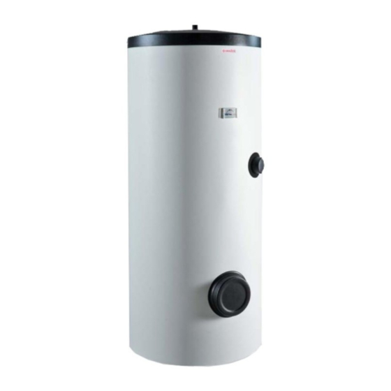
1 PRODUCT TECHNICAL SPECIFICATION 1.1 FUNCTION DESCRIPTION The OKC 250 (300, 400, 500, 750, 1000) NTR/HP stationary tank is designed for the preparation of hot sanitary water in combination with heat pump. Reheat can be carried out by the electric heater TJ 6/4". 1.2 DESIGN AND BASIC DIMENSIONS OF TANK 1.2.1 PRODUCT DESCRIPTION The tank receptacle is welded of steel plate and, as a unit, protected with enamel that resists to hot water. -
Page 5: Technical Data
1.2.2 TECHNICAL DATA OKC 250 OKC 300 OKC 400 OKC 500 OKC 750 OKC 1000 TYPE NTR/HP NTR/HP NTR/HP NTR/HP NTR/HP NTR/HP CAPACITY HEIGHT 1537 1558 1644 1914 2039 2053 DIAMETER 1050 MAXIMUM WEIGHT WITHOUT WATER MAXIMUM OPERATING PRESSURE IN THE TANK MAXIMUM OPERATING OVERPRESSURE IN THE EXCHANGER... - Page 6 OKC 250 NTR/HP OKC 250 NTR/HP 1537 Figure 1 3/4" outer 1460 1"outer 1060 3/4" inner 1/2" inner 6/4" inner 1330 1100 - 6 -...
- Page 7 OKC 300 NTR/HP OKC 300 NTR/HP 1558 1"outer Figure 2 3/4" inner 1/2" inner 6/4" inner 1579 1309 1148 - 7 -...
- Page 8 OKC 400-500 NTR/HP Figure 3 1"outer OKC 400 NTR/HP OKC 500 NTR/HP 3/4" inner 1644 1914 5/4" inner 1/2" inner 6/4" inner 1521 1790 1023 1138 1310 1081 1253 1237 1409 - 8 -...
- Page 9 OKC 750 – 1000 NTR/HP Figure 4 5/4"outer OKC 750 NTR/HP OKC 1000 NTR/HP 6/4" inner 2039 2053 3/4" inner 1017 1117 5/4" inner 1050 1891 1905 1123 1173 1491 1547 1433 1483 - 9 -...
-
Page 10: Pressure Losses
1.2.3 PRESSURE LOSSES OKC 250-500 NTR/HP OKC 250 NTR/HP OKC 300 NTR/HP OKC 400 NTR/HP OKC 500 NTR/HP Table 2 - 10 -... -
Page 11: Operation And Fitting Instructions
2 OPERATION AND FITTING INSTRUCTIONS 2.1 PUTTING THE TANK INTO OPERATION To connect the tank to water supply system, hot water heating system or power supply and, after testing the safety valve (accordingly with the manual attached to the valve), the tank can be put in operation. Procedure: a) Check the plumbing and electrical installation, including the connection to hot-water heating system. -
Page 12: Connecting A Tank To Hot Water System
2.2 CONNECTING A TANK TO HOT WATER SYSTEM Figure 5 The output hot water pipe on heaters with a volume of more than 200 litres is fitted with another DN 20 safety valve and opening pressure identical to the maximum operating pressure of the heater tank. This safety valve does not replace the safety valve on the cold water inlet. -
Page 13: Plumbing Fixture
2.3 PLUMBING FIXTURE Power water connects to pipes with 3/4" thread in the bottom part of the tank. Blue - cold water inlet; red - hot water outlet. For potential disconnection of the tank, the sanitary water inlets and outlets must be provided with screw coupling Js 3/4". The safety valve is mounted on the cold water inlet identified with a blue ring. -
Page 14: Connection Of Tank To Hot Water Distribution System
ACCEPTABLE SAFETY VALVE OPERATING MAXIMUM START-UP OVER- PRESSURE IN PRESSURE PRESSURE OF COLD WATER [MPa] WATER TANK PIPES [MPa] [MPa] up to 0.48 up to 0.56 up to 0.8 Table 3 2.4 CONNECTION OF TANK TO HOT WATER DISTRIBUTION SYSTEM The tank is placed on the floor next to the heating source or in its proximity. -
Page 15: Cleaning Of Tank And Exchange Of Anode Rod
2.5 CLEANING OF TANK AND EXCHANGE OF ANODE ROD Repetitive water heating causes limestone sediment on both the enamelled tank walls and chiefly the flange lid. The sedimentation depends on the hardness of water heated, its temperature, and amount of hot water consumed. -
Page 16: Spare Parts
2.6 SPARE PARTS - magnesium anode - contact thermometer When ordering spare parts always state the name of the part, the type and type number from the tank's plate. 3 IMPORTANT NOTICES 3.1 IMPORTANT NOTICES Without a proof issued by a professional company about performed electrical and plumbing fixture the warranty shall be void.
Need help?
Do you have a question about the OKC 250 NTR/HP and is the answer not in the manual?
Questions and answers