Table of Contents
Advertisement
Trilogy Series
PDL3000 Programming Instructions
ALARM LOCK
H I D
H I D
HID CORPORATION
KEYFOB
P L U G I N T H E N
ENTER YOUR CODE
PROX CARD
ALARM LOCK
AR-IR1 PRINTER
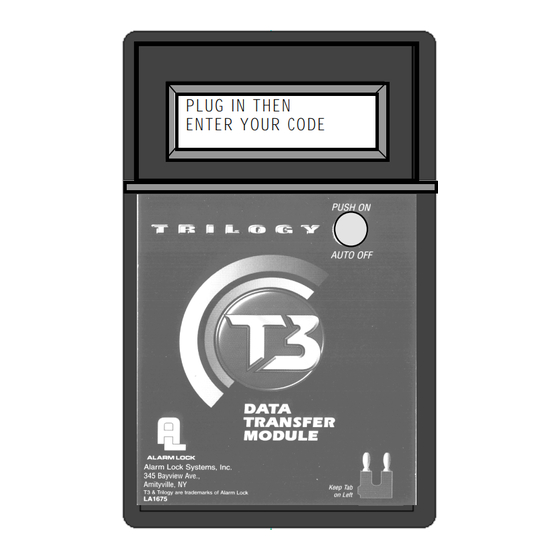
AL-DTM (Version 1)/AL-DTM2
DATA TRANSFER MODULE
Prox
Card
Reader
PROX CARD READER
PDL3000 Trilogy Series
Standalone Access Control System
with ProxCard Access
© ALARM LOCK 2000
WI1021 10/00
1
Advertisement
Table of Contents

Related Manuals for Alarm Lock PDL3000 series


Summary of Contents for Alarm Lock PDL3000 series
- Page 1 P L U G I N T H E N ENTER YOUR CODE PROX CARD ALARM LOCK AR-IR1 PRINTER AL-DTM (Version 1)/AL-DTM2 DATA TRANSFER MODULE Prox Card Reader PROX CARD READER PDL3000 Trilogy Series Standalone Access Control System with ProxCard Access © ALARM LOCK 2000 WI1021 10/00...
-
Page 2: Table Of Contents
Features ------------------------------------------------------------------------------------------------------------------------ 4 Audit Trail ------------------------------------------------------------------------------------------------------------------ 4 User Features ------------------------------------------------------------------------------------------------------------ 4 User Access --------------------------------------------------------------------------------------------------------------- 4 Prox Card Features ----------------------------------------------------------------------------------------------------- 4 500 Scheduled Events ------------------------------------------------------------------------------------------------- 5 Keypad and Computer Programming ------------------------------------------------------------------------------- 5 Accessories ------------------------------------------------------------------------------------------------------------------ 5 AL-IR1 Infrared Printer -------------------------------------------------------------------------------------------------- 5 AL-DTM2 Data Transfer Module ------------------------------------------------------------------------------------- 5 Prox Card Reader ------------------------------------------------------------------------------------------------------- 5 Additional Features ------------------------------------------------------------------------------------------------------ 6... - Page 3 Function Number 1. New Master Code -------------------------------------------------------------------------------------------------------------- 15 2. Add/Delete/Change User Codes ----------------------------------------------------------------------------------------- 15 3.-4. User Enable/Disable ---------------------------------------------------------------------------------------------------------- 16 5. User Enable with Timeout --------------------------------------------------------------------------------------------------- 16 6.-7. User Lockout Mode ----------------------------------------------------------------------------------------------------------- 16 9. Enable User 300 (Service Code) ----------------------------------------------------------------------------------------- 16 10.
-
Page 4: Features
The Alarm Lock PDL3000 Series Trilogy Standalone Access Control System is a State-Of-The-Art Microprocessor Based Programmable Keypad-Entry and PROX Security Lock. Audit Trail - 40,000 Events * ------- AUDIT LOG ------- 08/25/00 13:06:35 Tue 13:01:59 001 PROGRAM 56 • 13:01:29... -
Page 5: 500 Scheduled Events
The Alarm Lock PDL3000 Series Trilogy Standalone Access Control System is a State-Of-The-Art Microprocessor Based Programmable Keypad-Entry and PROX Card Security Lock. 500 Scheduled Events * • Programmed to Unlock/Lock • Enable/Disable Users • Enable/Disable Groups • Group 1 Activated Events •... -
Page 6: Additional Features
Ambush Function Keypad Lockout 1. Connect relay to a device able to properly monitor dry Programmable number of attempts before keypad lockout. contacts for an ambush condition. Programmable lockout time. 2. Program the Relay for Ambush Function Activated Non-Volatile Memory using Program Function 67(10). -
Page 7: Wiring And Power Up
Wiring The Three Methods of Powering Up are: • Red / Black (Operation without Batteries) - Optional Battery Replacement External 7.5 VDC Power Source must be used for operation • Power-Up Retain Lock Programming without batteries. • Power-Up Erase All Programming White / White (Remote Input) - Wire a Normally Open Contact to wires (white and white). -
Page 8: Preliminary Information
Lock Operation CODE TYPES Program level ability is fixed according to table on page 15. mportant: Before attempting to program any codes or functions, Note the following: The codes are defaulted to the tabulated group associations • While the lever or knob may be rotated at any time, the latch when adding codes using Program Function 2. -
Page 9: Getting Started
Battery Installation Remove the back cover and install battery pack. The lock will beep 3 times. To load the default program press any key within 5 seconds, the lock will beep slowly while the default values are loaded and beep rapidly upon completion. Entering Program Mode 1 2 3 4 5 6 1. -
Page 10: User Programming
User Programming Add a Basic User Code Program a User Code of 987. Use Function 2, and add the new user as User 12. Refer to Function 2 (page 15). ; 1 2 ; 9 8 7 : User Number (12) Code for User 12 Add another Basic User Code Program a User Code of 246. -
Page 11: Deleting A Proxcard/User Code
(Present CARD for User 150 within 10-second period, three beeps will sound at the keypad.) [Beep Beep Beep] Printer Functions (AR-IR1 PRINTER required) ALARM LOCK SYSTEMS, INC Printing the Lock’s Time, Date and Day. Refer to VERSION 9.00 org REC... -
Page 12: Methods Of Programming
(User Number) Communication The PDL3000 lock can also be programmed using a TO SERIAL PORT (DB-9) E.G. <COM 1> computer with Alarm Lock's DL-WINDOWS Software and AL-PCI cable. AL-PCI NOTE: Observe Tab Direction when inserting cable into DL3500 Lock. PDL3000... -
Page 13: Lock Operation
Verifying Basic Keypad User Codes Test User Code Entered in Getting Started for User 12. 9 8 7 Enter VALID CODE - The Green LED will flash momentarily and the sounder will beep a few times after a valid code is entered. INVALID CODE - The RED LED will flash several times and the sounder will beep several times after an invalid code is entered. -
Page 14: Quick Reference - Programming Functions
For more information on PDL3000 Programming Functions see pages 15 through 28. ; 4 8 New Master Code Enable Passage Mode ; 5 0 Add/Delete/Change User Codes Disable Passage Mode ; 4 9 User Disable (By User Number) Return Lock to Normal Passage Mode Schedule ;... -
Page 15: Programming Functions
USERS [ _ _ _ _ _ _ ] [ _ _ _ _ _ _ ] 1. New Master Code (User Number 1) (New Master Code) (Confirm New Master Code) • Master Code must be 6 digits-only. • Master Code is Keypad Code Access only, Prox Cards and Keyfobs cannot be programmed as the Master Code. -
Page 16: 4. User Enable/Disable
USERS (Continued) User Enable/Disable (By User Number) • User Number must be between 2 and 2000. NOTE: Will Enable/Disable users even if the user is associated with an enabled group. [ _ _ _ _ ] 3. Disable User (User Number) [ _ _ _ _ ] 4. -
Page 17: Clear All Schedules And Timeout Functions
CLEAR FUNCTIONS ; 1 2 ; 0 0 0 : 12. Clear All Schedules and Timeout Clears all programmed Schedules and all Timeout Functions. Includes Schedule Functions 72 to 93. Includes Timeout Functions 5, 25 to 34 and Function 47. NOTE: Up to 4 Timeout Functions may be pending at any one time. -
Page 18: 34. Group Enable/Disable With Timeout
NOTE: Clear All Timeout Functions by entering Function 13. GROUPS Group Enable/Disable with Timeout (Enter Timeout, XXX Hours) • Hours must be between 1 - 999. Enter the functions below to Enable/Disable groups for the amount of time entered in hours. NOTE: Only 4 Timeout Functions are allowed at any one time. -
Page 19: 38. Set Date
CLOCK SETTINGS ; 3 8 [ _ _ _ _ _ _ ] 38. Set Date (Date) • Use Month Day Year format - MMDDYY - Single digit months and days are entered with a preceding zero. • Enter Only the last two digits of the year. For Example: March. -
Page 20: 44. Clock Adjust
CLOCK ADJUST Clock Adjust • Number of seconds to Speed Up/Slow Down clock each day must be 0-55 seconds. Always consider the current setting when using this function. (Use of this function is not cumulative.) For example, if the clock needs to be sped up 10 seconds per day and the current setting is 10, program 20 seconds using Function 43. -
Page 21: 50. Passage Mode Enable/Disable - Schedule Will Not Override
PASSAGE MODE Passage Mode Enable/Disable - Schedule will not Override • Allows passage through the door without the need for a code using Function 48. Re-Lock using Function 49. • Programmed Schedules will not override the state of the lock using functions 48 and 49. If it is required that programmed schedules do override passage mode, Enable/Disable Passage mode using Functions 45/46. -
Page 22: 57. Printer Functions
PRINTER Hold the printer perpendicular to the Lock’s infrared LED as shown in Figure 1 and Figure 2. If the printer has been idle for some time, press the paper feed button to wake up printer. Infrared Infrared 1 2 3 4 5 6 7 8 9 : 0 ;... -
Page 23: Al-Dtm2 Door Number
• Door Number must be between 1- 96. Note: Door Number must be between 1-48 for AL-DTM (Version 1). For use with Alarm Lock’s AL-DTM2 Data Transfer Module. Using the AL-DTM2 up to 96 locks can be Downloaded/Uploaded and History LOGs can be retrieved. Enter a door number for each lock. -
Page 24: 68. Relay / System Features
RELAY / SYSTEM FEATURES ; 6 7 [ _ _ ] 67. Add Relay/System Features (Relay Function / System Feature) • Relay Functions Program 1 or more events below to activate the Relay for 2 seconds. 1. Remote Input while enabled 7. -
Page 25: 70. Enter Key
ENTER KEY Enter Key • When this function is enabled the user must press the key after any valid User Code entry; allows user codes which are subsets of other user codes. Example: 1 2 3 : is a valid user code; 1 2 3 4 : is a valid user code 1 2 3 4 5 6 : hold ;... -
Page 26: 87. Quick Schedules
QUICK SCHEDULES Quick Schedules - Enable Group • Group number must be 1-4 Enter the number of the group that is to be enabled for the time specified for the Quick Schedules below: ; 8 4 [ _ ] 84. Business Quick Schedule (Group) 7AM-5PM, Monday - Friday ;... -
Page 27: 91. Scheduled Relay Activation - Group 1 Activated
SCHEDULES GROUP 1 ACTIVATED Scheduled Relay Activation (Group 1 Activated) • Also program Relay Function 6 using Function 67 ( ; 6 7 ; 6 :). • For day enter: 1 for Sunday, 2 for Monday, 3 for Tuesday, 4 for Wednesday, 5 for Thursday, 6 for Friday and 7 for Saturday, 8 for Monday to Friday, 9 for Saturday and Sunday, 0 for all days of week. -
Page 28: 93. Scheduled Group 4 Enable - Group 1 Activated
Scheduled Group 4 Enable (Group 1 Activated) • For day enter: 1 for Sunday, 2 for Monday, 3 for Tuesday, 4 for Wednesday, 5 for Thursday, 6 for Friday and 7 for Saturday, 8 for Monday to Friday, 9 for Saturday and Sunday, 0 for all days of week. -
Page 29: Using Advanced Features
Note: Advanced User Programming The example to add Add a User that is a member of Group 2 & Group 3 Users to Group 2 and Group been Program a User Code of 789 that is a member of Group 2. Refer to Function 2 (page 15). Use Function 2, selected due to the fact and add the new user as User 101 (Users 101-150 are members of Group 2): that Group 1 Activated... -
Page 30: Programming Record Sheet
Default Values are shown in parentheses. Function Number(s) Function Name Programming Daylight Savings Time Code 01-24 DST Code 43/44 0-55 Clock Adjust Seconds 52/53/54 Pass Time (3 sec) 10 sec 15 sec AL-DTM Door Number 1-96 (48 for AL-DTM (Version 1) Door Number Set Lockout Attempts 1-9 Attempts... -
Page 31: User Code Record Sheet
User Number User Code Group User Name (1-2000) (3-6 digits) Association Note: For a complete list of user codes, obtain a printout from either the remote printer (Program Function 56) or using the DL-WINDOWS Software. -
Page 32: Schedule Record Sheet
Day(s) Up to 500 scheduled functions can be programmed (Up to only 150 using AL-DTM2). For Day Enter : 1 = Sunday, 2 = Monday, 3=Tuesday, 4 Wednesday Function Number Time Function Name 5 = Thursday, 6 = Friday, 7=Saturday, 8 = Monday - Friday 9 = Saturday and Sunday, 0=All days of the week Enter time of day in 24 hour format (00:00- 23:59) -
Page 33: Definitions
ACCESS = Entry into a restricted area. AMBUSH = An AMBUSH CODE used before a USER CODE and programmed for Relay Ambush can be used to alert security, or trip a silent-alarm on a Burglary Control Panel. AUDIT TRAIL = A log of previously date/time stamped events that have occurred. BURGLARY CONTROL PANEL = Provides local alarm and remote communication to request security for burglary/break-in. - Page 34 FUNCTION (also called Programming Functions) = are the numbers used to program lock features (enabling/disabling Users, User Groups, Passage Mode, Schedules, etc.). GROUP • USER GROUP = Defining a user to specific groups, allows user entry when the group is allowed entry. •...
- Page 35 REMOTE INPUT = Entry into a restricted area, by pressing a button connected to the REMOTE INPUT WIRES (White and White) by someone on the other side of the door. SCHEDULE = A programmed operation (enable/disable, lock/unlock, etc.) on a specific weekday (Sunday through Saturday) and time. SCHEDULES, QUICK = Any one of four most common types of schedules can be programmed.
-
Page 36: Warranty
ALARM LOCK is not an insurer of either the property or safety of the user's family or employees, and limits its liability for any loss or damage including incidental or consequential damages to ALARM LOCK's original selling price of the product regardless of the cause of such loss or damage. - Page 37 Part 15 Manual Statement The following statement should be conspicuously located in bold letters in the instruction manual: CAUTION: Changes modifications expressly approved Napco Security Systems could void user’s authority operate equipment. RADIO AND TELEVISION INTERFERENCE This equipment has been tested and found to comply with the limits for a Class B digital device, pursuant to Part 15 of rules.
Need help?
Do you have a question about the PDL3000 series and is the answer not in the manual?
Questions and answers