Table of Contents
Advertisement
Quick Links
Advertisement
Table of Contents

Related Manuals for Entron EN7000v2


Summary of Contents for Entron EN7000v2
- Page 1 User Manual EN7000v2 Firmware Version 2.27 July 23 Document No. 700257...
- Page 2 TRADEMARKS BF ENTRON and/or its affiliates’ trademarks may not be used in connection with any product or service that is not BF ENTRON’s, in any manner this is likely to cause confusion among customers or in any manner that disparages or discredits BF ENTRON.
- Page 3 Document Changes Number Languages This document is only published in the English language. Copyright © 2021 BF ENTRON and/or its affiliates. All rights reserved P a g e Product Model: EN7000v2 Firmware Version: 2.27 July 23 | Doc No 700257...
-
Page 4: Table Of Contents
2.11 Preventative Maintenance ............................49 COMMUNICATIONS SETUP ........................... 51 Overview .................................... 51 Set the IP Address of the Control ..........................53 Copyright © 2021 BF ENTRON and/or its affiliates. All rights reserved P a g e Product Model: EN7000v2 Firmware Version: 2.27... - Page 5 Program Selection ............................... 116 5.8.1 Internal Program Selection.....................................117 5.8.2 External Program Selection ....................................117 Copyright © 2021 BF ENTRON and/or its affiliates. All rights reserved P a g e Product Model: EN7000v2 Firmware Version: 2.27 July 23 | Doc No 700257...
- Page 6 Inputs ............................................138 9.2.3 Outputs ............................................140 9.2.4 Programming Parameters ....................................145 Ethernet/IP (EIP) ................................ 157 Copyright © 2021 BF ENTRON and/or its affiliates. All rights reserved P a g e Product Model: EN7000v2 Firmware Version: 2.27 July 23 | Doc No 700257...
- Page 7 Program the WAV Output for Each Weld Program in the Cascade Sequence ..............208 11.2.4 Link Programs Together (Cascade) ...............................211 Copyright © 2021 BF ENTRON and/or its affiliates. All rights reserved P a g e Product Model: EN7000v2 Firmware Version: 2.27...
- Page 8 Configure Control for Extended Mode ..............................213 11.3.2 Assign Electrode to a Transformer ................................215 11.3.3 Programming a Multi-Welder/Cascade Sequence ..........................215 11.4 Configuring & Calibrating EN7000v2 with the WSP3 Pendant ..............218 11.4.1 Configure the Weld Control ..................................219 11.4.2 Reset & Turn Off Electrode Stepper ..............................221 11.4.3...
-
Page 9: Background
NFPA 70E or equivalent standard in your location. This manual has been written for the EN7000v2 AC weld control product line with an EN7000v2 weld timer. The manual applies to the V2.27 version of firmware on the EN7000V2 timer. -
Page 10: Explanation Of Symbols
HELPFUL TIP The Helpful Hint symbol is used to provide additional information on a topic that may be helpful to the user. Copyright © 2021 BF ENTRON and/or its affiliates. All rights reserved 10 | P a g e Product Model: EN7000v2 Firmware Version: 2.27... -
Page 11: Important Safety Instructions
BACKGROUND Important Safety Instructions Important Safety Instructions Before installing, starting up, or operating the EN7000v2, carefully read all safety instructions to ensure safe use of the product. SAVE THESE INSTRUCTIONS The safety instructions are part of the product. Keep the instructions in a safe and easily accessible place near the product. - Page 12 Always ensure cooling water is adequately flowing at the proper rate, temperature, and is of sufficient quality. For water quality requirements, refer to AWS J1.2M/J1.2.2016 Guide Installation and Maintenance of Resistance Welding Machines. Copyright © 2021 BF ENTRON and/or its affiliates. All rights reserved 12 | P a g e Product Model: EN7000v2 Firmware Version: 2.27...
-
Page 13: Technical Support
BACKGROUND Technical Support Technical Support 1.5.1 Internet The latest version of the documentation and other helpful resources in the ENTRON Document Library page found in the Resource section of the ENTRON website: https://www.entroncontrols.com 1.5.2 Documentation Request Documentation, user instructions and technical information can be requested by emailing ENTRON Controls at customerservice@entroncontrols.com... -
Page 14: Introduction
2 INTRODUCTION Weld Control The EN7000v2 Weld Timer Control is primarily a single-phase 50/60 Hz AC control. It can be configured for Single Gun, Multi-Weld Cascade, Seam Weld, Roll Spot, Analog and 3 Phase DC. Key Configurations of the EN7000v2 for AC & 3 Phase DC welding: 1) Available in two models, with or without Touch Screen on board programmer. -
Page 15: Product Hardware Specifications
Communication via Ethernet/IP, RS232, RS485, MODBUS TCP/IP, or MODBUS RTU An EN7000v2 weld control is also available in a Multi-Welder (Cascade) configuration. This configuration allows a user to control multiple weld transformers and multiple weld actuators with a single control. The features of the multi-weld configuration are: •... -
Page 16: En7000V2 Weld Timer Specifications
77 degrees Fahrenheit or 25 degrees Temperature Centigrade pH-7-8.5 Water Quality Hardness max 12.5(UK) 10.5(US) Copyright © 2021 BF ENTRON and/or its affiliates. All rights reserved 16 | P a g e Product Model: EN7000v2 Firmware Version: 2.27 July 23 | Doc No 700257... -
Page 17: Main Component Overview
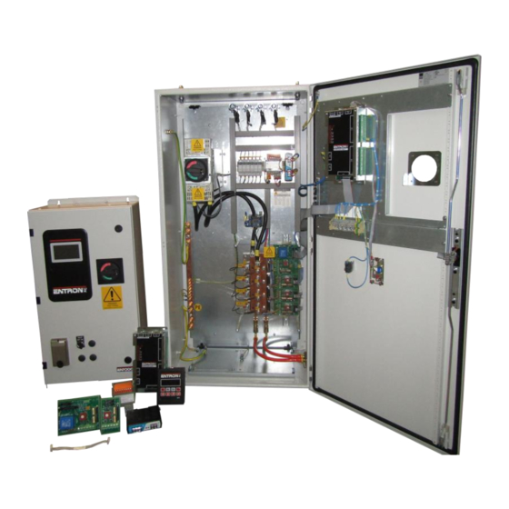
An algaecide is recommended. Table 5: EN7000v2 Cooling Water Specifications Main Component Overview The EN7000v2 weld control is an assembled unit. The major components of the standard 150M/1200A EN7000v2 configuration are identified below and in Figure 1: EN7000v2 150M 250A Control Layout. -
Page 18: Wiring Diagrams
Wiring Diagrams Wiring Diagrams The EN7000v2 weld timer control is designed to operate with various size SCRs and up to 8 welding transformers. This section provides the electrical schematic for customer connections when interfacing the EN7000v2 and a generic Weld Control wiring diagram. - Page 19 10-64-0C-00-04-B1-00-10 EN7000TS/P-1200D/EIP 10-64-0D-00-04-A1-00-10 EN7000TS/P-1800C/EIP Table 6: Standard Product Wiring Diagram List by Part Number Copyright © 2021 BF ENTRON and/or its affiliates. All rights reserved 19 | P a g e Product Model: EN7000v2 Firmware Version: 2.27 July 23 | Doc No 700257...
-
Page 20: Customer Connections Diagram (3U3633)
2.5.1 Customer Connections Diagram (3U3633) The user connections for the EN7000v2 weld timer control for inputs and outputs are defined in Wiring Diagram Figure 2: 3U3633. This wiring diagram applies to all EN7000’s. Figure 2: 3U3633 Copyright ©... -
Page 21: Standard Machine
Below is a schematic showing an example of a single AC transformer connected to a single set of electrodes. The schematic represents a system where the EN7000v2 weld timer controls the actuation of the weld sequence. By activating the weld air valve (WAV) output to close the weld cylinder and execute the programmed sequence in the selected weld schedule (Program). - Page 22 Multi-Welder control must be specified at the time of order with the number of transformers to be controlled. Cascade / MUX The EN7000v2 Cascade type weld controls can be identified by the part description. UK built controls the description must contain e.g 150M or 300Mx2,3-8 which means additional SCRs have been installed in the cabinet to fire additional transformers.
- Page 23 INTRODUCTION Multi-Welding Machine Figure 5: Multi-Welder Machine Schematic Copyright © 2021 BF ENTRON and/or its affiliates. All rights reserved 23 | P a g e Product Model: EN7000v2 Firmware Version: 2.27 July 23 | Doc No 700257...
-
Page 24: Modes Of Current Control
Modes of Current Control The EN7000v2 weld timer’s primary function is to control the magnitude and duration of the weld current. There are two different modes of current control. The mode is set with each weld schedule. CCR Current control can be calibrated to match an external weld current meter. -
Page 25: Phase Angle Mode "Pha
The current parameter in kA is adjustable by the user but the heat % required is automatically adjusted by the EN7000v2 weld control. The current target is programmed in units of Amps or kiloampere (kA) dependent upon measuring source and calibration set-up. -
Page 26: Installation
Installation Installation The installation of the EN7000v2 weld control should be performed by a trained electrician and all local safety protocols must be followed when installing the unit. These instructions should be carefully read before installation. Failure to adhere to these instructions may invalidate the warranty on the control 2.9.1... - Page 27 Wire all desired I/O connections. Figure 7: EN7000 Control with Access Figure 8: EN7000 Control without Access Points Plate Only Copyright © 2021 BF ENTRON and/or its affiliates. All rights reserved 27 | P a g e Product Model: EN7000v2 Firmware Version: 2.27...
- Page 28 Inspect all electrical connections inside the cabinet to verify connections are tight and secure. 14) Close and Lock Door Close the cabinet door. Using the provided key rotate the door locks to seal the cabinet door. Copyright © 2021 BF ENTRON and/or its affiliates. All rights reserved 28 | P a g e Product Model: EN7000v2 Firmware Version: 2.27...
- Page 29 20) Connect Desired Programming Device Connect the desired programming device to the control. 21) Configure the Control Configure the EN7000v2 welding control to your required resistance welding process. See the Configure the Control section for more details.
-
Page 30: Configure The Control
The control is now ready for use. Begin programming or uploading your weld schedules to the EN7000v2 weld timer. 2.9.2 Configure the Control The EN7000v2 weld timer is a flexible device that can be adapted in a variety of ways to fit your welding application. The configuration defines the following parameters: • •... - Page 31 Installation Figure 10: NetFlash Configuration Tab The features checkbox allows the user to access advanced features in the control by selecting Extended. The EN7000v2 must be restarted for this change to take effect. VALUE Description Default setting with basic features. This is selected for spot, spot repeat, and Standard projection welding applications.
- Page 32 The 2 Stage input is checked at the start of every program within a cascade Every sequence Copyright © 2021 BF ENTRON and/or its affiliates. All rights reserved 32 | P a g e Product Model: EN7000v2 Firmware Version: 2.27...
- Page 33 B) SCR/Transformer can be assigned to up to 8 Electrodes, thereby allowing weld programs to turn on the assigned Transformer in a Cascade control. – See Cascade operation. Copyright © 2021 BF ENTRON and/or its affiliates. All rights reserved 33 |...
- Page 34 The Analog Control setting diverts heat / current control to the Analog input port. The Heat / Current parameters in any program will be ignored. Instead, a 0-10V input will adjust current as needed from external means. Copyright © 2021 BF ENTRON and/or its affiliates. All rights reserved 34 |...
- Page 35 Installation 2.9.2.13 Retract The Retract parameter defines the requirements for inputs and outputs related to a retraction value. The profiles of each setting are defined below. The EN7000v2 must be restarted for this change to take effect. Value Description Off/Simple...
- Page 36 The local operating Line Frequency should be set. 50Hz or 60Hz. 2.9.2.16 I/O Source The I/O Source defines the communication of the inputs and outputs for the EN7000v2 weld timer. The EN7000v2 must be restarted for this change to take effect.
-
Page 37: Current Calibration
The time on the control can be manually set by clicking the Set action button. This allows a user to set the physical time on the EN7000v2 to their time zone to ensure fault monitoring and the weld data log are timestamped to the user’s local time. - Page 38 Scales the Analog control CCR 0V= 0-500.0 input for CCR operation Copyright © 2021 BF ENTRON and/or its affiliates. All rights reserved 38 | P a g e Product Model: EN7000v2 Firmware Version: 2.27 July 23 | Doc No 700257...
- Page 39 Step 3 Secondary Current Secondary Current Value Displayed Value Displayed Copyright © 2021 BF ENTRON and/or its affiliates. All rights reserved 39 | P a g e Product Model: EN7000v2 Firmware Version: 2.27 July 23 | Doc No 700257...
- Page 40 If the STATUS shows conduction is at near 99.9%. Power Factor is set. Repeat the procedure for each electrode program to be used. Copyright © 2021 BF ENTRON and/or its affiliates. All rights reserved 40 | P a g e Product Model: EN7000v2 Firmware Version: 2.27...
- Page 41 CT Turns-Ratio – Not matched to external meter. The Turns Ratio setting allows the user to set the turns-ratio of the weld transformer connected to the EN7000v2. The turns ratio is used to calculate the secondary current from the measured primary current.
- Page 42 The Points 1&2 calibration method is more accurate than the Turns-Ratio method. This procedure requires an external current measuring device such as an ENTRON WA2 Weld Analyzer. The process requires the user to establish the relationship between the primary current and the secondary current over the desired output range. After calibration, the EN7000v2 uses the calibration table to calculate the secondary current from the measured primary current.
- Page 43 Is2 = Secondary Weld Current 2 (measured by the external current monitor) 3) Navigate to the Calibrate Current tab 4) Enter the Ip1, Ip2, Is1 and Is2 values into the table as shown below Copyright © 2021 BF ENTRON and/or its affiliates. All rights reserved 43 | P a g e Product Model: EN7000v2 Firmware Version: 2.27...
- Page 44 Calibration. Secondary Measuring requires an external toroid (Rogowski coil). The toroid is connected around the welding transformer secondary. Most such coils have a nominal output of 150 mV/kA. The EN7000v2 provides a sensitivity parameter which may be adjusted to provide absolute matching with an external current meter.
- Page 45 Main Heat Mode to PHA d. set the Heat value to a low value such as 50.0% e. set the Main heat time to 10 cycles. Copyright © 2021 BF ENTRON and/or its affiliates. All rights reserved 45 | P a g e Product Model: EN7000v2 Firmware Version: 2.27...
- Page 46 15) Produce a short circuit weld Compare the Secondary Current measurement on the external meter with the Secondary Current output of the EN7000v2 viewed in the Log tab or metrics window, timer touch screen status or WSP3 Pendant status. 16) Navigate to the Calibrate Current tab 17) Adjust the Sensitivity value accordingly.
-
Page 47: Force Calibration
2.10 The EN7000v2 weld controller has the ability to control weld force and read the weld force via analog signals. The analog input allows the control to read the output of an external force sensor (load cell) or a proportional pressure sensor to measure force. -
Page 48: Force Calibration Procedure
If the force reading is at the low end of the cylinder’s output, enter in Point1 b. If the force reading is at the low end of the cylinder’s output, enter in Point2 Copyright © 2021 BF ENTRON and/or its affiliates. All rights reserved 48 |... -
Page 49: Preventative Maintenance
Table 9 may require power to test the function of the electrical component. Appropriate Personal Protective Equipment must always be worn during maintenance and inspection of the EN7000v2 Weld Control. WARNING! All preventative maintenance procedures should only be performed by... - Page 50 10. Failure to comply may result in a hazard with a high level of risk which, if not avoided, will result in immediate, serious personal injury or loss of life. Copyright © 2021 BF ENTRON and/or its affiliates. All rights reserved 50 | P a g e Product Model: EN7000v2 Firmware Version: 2.27...
-
Page 51: Communications Setup
3 COMMUNICATIONS SETUP Overview The EN7000v2 weld controller is designed to communicate with external devices such as PLCs with standard communication protocols for industrial systems. This section of the manual describes how to configure the EN7000v2 weld control to the user desired communication method. - Page 52 The RS485 port supports I/O data exchange and welding RS485 MODBUS-RTU COM2 programming parameters via MODBUS communication. Copyright © 2021 BF ENTRON and/or its affiliates. All rights reserved 52 | P a g e Product Model: EN7000v2 Firmware Version: 2.27...
-
Page 53: Set The Ip Address Of The Control
Set the IP Address of the Control Set the IP Address of the Control The IP Address is critical for communication with external devices. The EN7000v2 has an integrated sub-system for the Ethernet and EtherNet/IP communications on COM4, COM5, and COM6. - Page 54 9) Now that the control is known by the PC, the IP Address, Subnet Mask, and Gateway can be updated from the COM Ports tab in NetFlash. a. Click the Load from Control Icon Copyright © 2021 BF ENTRON and/or its affiliates. All rights reserved 54 | P a g e Product Model: EN7000v2 Firmware Version: 2.27...
- Page 55 Navigate to Any tab to begin programming the control. ie Configure c. Update the desired fields. Then press Enter or Tab to push the change to the control Copyright © 2021 BF ENTRON and/or its affiliates. All rights reserved 55 |...
-
Page 56: Ethernet Communications
Ethernet Communications Ethernet Communications The EN7000v2 weld control has one built in Ethernet connector on the timer board. The Ethernet connector supports EtherNet/IP communications with EIP devices. The Ethernet connector also supports read write functions with MODBUS-TCP/IP external devices, programming via the NetFlash™, and read only data outputs. - Page 57 For text fields updated with a keyboard entry, the user must press Enter or Tab after a field change to push the data to the control. Copyright © 2021 BF ENTRON and/or its affiliates. All rights reserved 57 |...
-
Page 58: Configure For Ethernet/Ip (Eip)
The EN7000v2 Control supports the Common Industrial Protocol (CIP TM) through Ethernet/IP (EIP). With Ethernet/IP communication, the EN7000v2 control provides Implicit messaging and Explicit messaging. To enable Ethernet IP I/O control. The EN7000v2 I/O in EIP field must have the I/O source of the control’s input set to COM6 (E/IP). -
Page 59: Configure For Modbus-Tcp/Ip
7) Restart the control for the I/O source field change to take effect by clicking the Restart control icon 8) Connect the remote MODBUS Device to the EN7000v2 weld control and attempt to ping the weld control IP Address to verify the connection. -
Page 60: Modbus-Rtu
MODBUS-RTU MODBUS-RTU The EN7000v2 supports MODBUS-RTU communication to exchange both I/O data with a remote MODBUS device. The remote MODBUS device communicates with the EN7000v2 control via a DSUB9 (RS485) cable. The RS485 port on the EN7000v2 weld control is shown below in... - Page 61 7) Restart the control for the I/O source field change to take effect by clicking the Restart control icon 8) Connect the remote MODBUS Device to the EN7000v2 weld control and attempt to ping the weld control IP Address to verify the connection.
-
Page 62: Wsp3 Pendant
The WSP3 is a flexible device designed to work with the entire EN7000v2 and iPAKv2 product families. In other words, one WSP3 Pendant can be used to program multiple ENTRON controls in a user’s facility. -
Page 63: Entron Programming Tools
This section defines information on programming with the NetFlash™ software and the WSP3 pendant. Both tools can be used to configure and program an iPAKv2 or EN7000v2 product. For information on programming the EN7000v2 weld control from a PLC or remote device using EtherNetIP or MODBUS refer to the READ &... -
Page 64: Installing Netflash
The NetFlash™ has a Toolbar on the top of the window for navigation to sub-windows for setup. The Status bar is located on the bottom of the window and shows the status of connection information. Copyright © 2021 BF ENTRON and/or its affiliates. All rights reserved 64 |... -
Page 65: Restart Control
Set the Control Type. NetFlash can be used to program other Select Control Type ENTRON Products Table 13: NetFlash Toolbar Icons Copyright © 2021 BF ENTRON and/or its affiliates. All rights reserved 65 | P a g e Product Model: EN7000v2 Firmware Version: 2.27... - Page 66 Target IP and Host The Target IP address and the HOST IP address must be on the same sub-net, otherwise the communication is impossible. Copyright © 2021 BF ENTRON and/or its affiliates. All rights reserved 66 | P a g e Product Model: EN7000v2 Firmware Version: 2.27...
- Page 67 1) WS2003, iPAK 2) EN7000, iPAK2 Communication Error Communication will fail if the control type is not properly set. Copyright © 2021 BF ENTRON and/or its affiliates. All rights reserved 67 | P a g e Product Model: EN7000v2 Firmware Version: 2.27...
-
Page 68: Networks Window
IP address. Multiple networks can be defined (e.g. for different areas within a factory). An example of the Networks Window is shown below. Copyright © 2021 BF ENTRON and/or its affiliates. All rights reserved 68 |... - Page 69 Ping Target IP control is physically connected to the network. Address Table 15: NetFlash Network Window Icons Copyright © 2021 BF ENTRON and/or its affiliates. All rights reserved 69 | P a g e Product Model: EN7000v2 Firmware Version: 2.27...
-
Page 70: Edit Control Parameters
The edit window has its own tool-bar. Example: Edit Control Parameters window after clicking the Load from control icon. Copyright © 2021 BF ENTRON and/or its affiliates. All rights reserved 70 | P a g e Product Model: EN7000v2 Firmware Version: 2.27... - Page 71 Click on the icon to open a browser window to set the file name and location. Table 16: NetFlash Edit Window Icons Copyright © 2021 BF ENTRON and/or its affiliates. All rights reserved 71 | P a g e Product Model: EN7000v2 Firmware Version: 2.27...
-
Page 72: Editing Parameters
A control button provides a means of signaling the indicated Button action to the control. Table 17: NetFlash Editing Parameters Icons Copyright © 2021 BF ENTRON and/or its affiliates. All rights reserved 72 | P a g e Product Model: EN7000v2 Firmware Version: 2.27... -
Page 73: Log Tab
67 records by clicking Get all. Click the Clear history option to clear the records stored on the control. Table 18: NetFlash Log Tab Icons Copyright © 2021 BF ENTRON and/or its affiliates. All rights reserved 73 | P a g e Product Model: EN7000v2 Firmware Version: 2.27... -
Page 74: Flash Programming Tool
Click on the tool and the flash programming window opens: The icons shown in the Flash Window are defined in Table Copyright © 2021 BF ENTRON and/or its affiliates. All rights reserved 74 | P a g e Product Model: EN7000v2 Firmware Version: 2.27... - Page 75 Table 19: NetFlash Flash Window Icons Copyright © 2021 BF ENTRON and/or its affiliates. All rights reserved 75 | P a g e Product Model: EN7000v2 Firmware Version: 2.27...
-
Page 76: Setup Netflash™ Users/Security
2) Enable/disable the NetFlash™ security feature. 3) Login/logout users. The definition of each of the icons is defined in Table Copyright © 2021 BF ENTRON and/or its affiliates. All rights reserved 76 | P a g e Product Model: EN7000v2 Firmware Version: 2.27... - Page 77 Click the box to turn the security system on or off Security Security Help Displays information about the security scope field. Table 20: NetFlash Security Icons Copyright © 2021 BF ENTRON and/or its affiliates. All rights reserved 77 | P a g e Product Model: EN7000v2 Firmware Version: 2.27...
-
Page 78: Wsp3
The WSP3 can be used to access diagnostic information and set all parameters in the weld control. The WSP3 uses RS232 to communicate with the EN7000v2 and should be connected to the COM3 port on the timer. Complete controls typically come pre-wired with a COM3 connection mounted to the door of the control to allow a customer to connect to the EN7000v2 without entering the cabinet. -
Page 79: Diagnostic Screen
When editing parameters, you can quickly switch to the diagnostic screen by pressing the Enter key, then switch back to the menu item by pressing F. Copyright © 2021 BF ENTRON and/or its affiliates. All rights reserved 79 | P a g e Product Model: EN7000v2 Firmware Version: 2.27... -
Page 80: Menus
To open a sub-menu, the user should press the ENTER key. To return the previous menu, a user should press the F key. Figure 19: WSP3 Menus Copyright © 2021 BF ENTRON and/or its affiliates. All rights reserved 80 | P a g e Product Model: EN7000v2 Firmware Version: 2.27... -
Page 81: Built-In Touch Screen
4.3.1 Touch screen The EN7000v2-TS has a navigation touch screen which displays buttons and scroll bars to allow the user to navigate menus. On power up the display will show the Splash screen shown in Figure 20: Splash screen. - Page 82 When editing parameters, you can quickly return to the Status screen by pressing the icon , then switch back to previous menu by pressing icon again. Copyright © 2021 BF ENTRON and/or its affiliates. All rights reserved 82 | P a g e Product Model: EN7000v2 Firmware Version: 2.27...
-
Page 83: Main Menu
Current sub-menu. The Main heat parameter in this example is set at 99.9% and the user will change this parameter to 50.0%. Figure 25 the user is shown pressing the Main heat button. Copyright © 2021 BF ENTRON and/or its affiliates. All rights reserved 83 | P a g e Product Model: EN7000v2 Firmware Version: 2.27... - Page 84 The user can then change the value of the parameter using the numerical buttons as shown in Figure 27: Main heat new value. Copyright © 2021 BF ENTRON and/or its affiliates. All rights reserved 84 | P a g e Product Model: EN7000v2 Firmware Version: 2.27...
- Page 85 Figure 28: Main heat value conformation After the user has pressed the check box they will be returned to the Current: Program sub-menu as shown in Figure Copyright © 2021 BF ENTRON and/or its affiliates. All rights reserved 85 | P a g e Product Model: EN7000v2 Firmware Version: 2.27...
- Page 86 Figure 29: Current: Program example After a parameter value has been changed the user can quickly return to the Status page by pressing on the icon. Copyright © 2021 BF ENTRON and/or its affiliates. All rights reserved 86 | P a g e Product Model: EN7000v2 Firmware Version: 2.27...
-
Page 87: Programming Weld Programs
(tips) and the actuator used to generate the weld force from the start to the end of the sequence. The EN7000v2 weld controller is a flexible system that allows a user to create a unique weld program (schedule) for their specific machine application. -
Page 88: Parameters
Figure 31: Weld Sequence Diagram Parameters The EN7000v2 weld control has a flexible design with options that allows a user to create an extensive variety of weld programs. An infinite number of combinations may sound daunting; Each weld program will follow the same squeeze,... - Page 89 Weld Timing Parameters The EN7000v2 controls the weld sequence I/O in conjunction with the weld parameters. The parameters are stored in programs in the weld control. Typically, a unique weld program (schedule) is stored for a specific job or weld. The EN7000v2 control can store up to 256 weld programs.
- Page 90 Table 23. It should be noted that for each current interval, the firing mode must be defined. The modes of current control are: Copyright © 2021 BF ENTRON and/or its affiliates. All rights reserved 90 | P a g e Product Model: EN7000v2 Firmware Version: 2.27...
- Page 91 To use Force control, the EN7000v2 analog output parameter must be set to ANALOG OUT: FORCE. The EN7000v2 has the ability to control up to 8 air valves. Multi-valve operation requires Extended mode to be enabled in the configuration.
- Page 92 Valve Control Parameters The EN7000v2 has eight discrete outputs (AV1 – AV8) that can be operated independently during a welding sequence. The valves are categorized as WAV, MOTOR, or AUX valves. The outputs are 24 V dc short circuit protected, monitored guided contact relay.
- Page 93 5.3.1.6 Multi-Electrode Parameters The EN7000v2 is available for Multi-Welders where the EN7000v2 weld controller can control up to 8 valves and 8 transformers (see section XX for diagram). The EN7000v2 must be configured for Extended mode to use the Multi-Electrode functions.
-
Page 94: Weld Program Types
A weld sequence is provided for each of these common welds to give the user an idea of the current and force profiles that can be created with the EN7000v2. This list is not exhaustive and is only intended to provide an overview of what can be done with the control. - Page 95 A weld sequence timing diagram showing pulsation spot weld with the air valve actuated by the EN7000v2 weld controller and the main heat is pulsed three times to create the weld nugget is shown in...
- Page 96 The electrodes will open during the OFF sequence which allows the workpiece to be repositioned for the next weld. Copyright © 2021 BF ENTRON and/or its affiliates. All rights reserved 96 | P a g e Product Model: EN7000v2 Firmware Version: 2.27...
- Page 97 PROGRAMMING WELD PROGRAMS Weld Program Types A weld sequence timing diagram showing a spot repeat weld with the air valve actuated by the EN7000v2 weld controller and the squeeze, weld, hold sequence repeated while the START input is maintained (see Figure 34).
- Page 98 Post-heat Pulsations Force Profile Roll Spot Table 32: Seam Weld Timing Diagram Weld Options Copyright © 2021 BF ENTRON and/or its affiliates. All rights reserved 98 | P a g e Product Model: EN7000v2 Firmware Version: 2.27 July 23 | Doc No 700257...
- Page 99 MOTOR – 2 Stage The initiation of the MOTOR output signal is a function of the Second Stage parameter. Copyright © 2021 BF ENTRON and/or its affiliates. All rights reserved 99 | P a g e Product Model: EN7000v2 Firmware Version: 2.27...
- Page 100 8) The START input is disabled 9) The active Squeeze, Weld, Hold sequence is completed 10) The WAV output is disabled to release the actuator Copyright © 2021 BF ENTRON and/or its affiliates. All rights reserved 100 | P a g e Product Model: EN7000v2 Firmware Version: 2.27...
-
Page 101: Programming A Spot Weld With The Wsp3
37. This example is based on a machine with the configuration defined below: • Standard Machine with a single air valve controlled by the EN7000v2 • The unit has been configured and calibrated for Secondary Regulation using a toroid sensor. - Page 102 Set all of the configuration FEATURES: STANDARD parameters as shown below. STAGE: STAGE: ONCE Copyright © 2021 BF ENTRON and/or its affiliates. All rights reserved 102 | P a g e Product Model: EN7000v2 Firmware Version: 2.27 July 23 | Doc No 700257...
- Page 103 Now use the Down Key to EDIT TIME EDIT TIME menu and press RETURN. To Scroll Down Copyright © 2021 BF ENTRON and/or its affiliates. All rights reserved 103 | P a g e Product Model: EN7000v2 Firmware Version: 2.27...
- Page 104 To Scroll Down EDIT CURRENT Arrow key to EDIT CURRENT option and press Return key To Enter Menu Copyright © 2021 BF ENTRON and/or its affiliates. All rights reserved 104 | P a g e Product Model: EN7000v2 Firmware Version: 2.27...
- Page 105 *** END OF LIST *** selected parameter. Press both keys simultaneously to set the parameter to 0 or the minimum value. Copyright © 2021 BF ENTRON and/or its affiliates. All rights reserved 105 | P a g e Product Model: EN7000v2 Firmware Version: 2.27...
- Page 106 The Status Screen will update after each weld. Table 35: Instructions to Program a Simple Spot Weld with the WSP3 Copyright © 2021 BF ENTRON and/or its affiliates. All rights reserved 106 | P a g e Product Model: EN7000v2 Firmware Version: 2.27...
-
Page 107: Programming A Spot Weld With Netflash
38. This example is based on a machine with the configuration defined below: • Standard Machine with a single air valve controlled by the EN7000v2 • The unit has been configured and calibrated for Secondary Regulation using a toroid sensor. - Page 108 1) Open the NetFlash™ application and connect to the target control 2) Load the parameters from the control by clicking the Load from Control icon 3) Navigate to the Configuration tab to verify the EN7000v2 is configured for a spot weld on a standard machine:...
- Page 109 17) Set the Main heat parameter in cycles to define the duration of the pulse. 18) Turn the Monitor On for the Main Current to store the measured secondary current in the History Log file. Copyright © 2021 BF ENTRON and/or its affiliates. All rights reserved 109 | P a g e Product Model: EN7000v2 Firmware Version: 2.27...
- Page 110 22) The Spot Weld program corresponding to the spot welding timing diagram in Figure 38 has now been stored in the EN7000v2 weld control and it is ready for use. Figure 39: Spot Weld Program Example in NetFlash Copyright © 2021 BF ENTRON and/or its affiliates. All rights reserved...
-
Page 111: Programming A Spot Weld With Touchscreen
Figure 37. This example is based on a machine with the configuration defined • Standard Machine with a single air valve controlled by the EN7000v2 • The unit has been configured and calibrated for Secondary Regulation using a Toroid sensor Figure 40: Simple Spot Welding Timing Diagram Copyright ©... - Page 112 Configuration Menu A warning message appears prior to entering the Configuration menu. Press the check box to proceed. Copyright © 2021 BF ENTRON and/or its affiliates. All rights reserved 112 | P a g e Product Model: EN7000v2 Firmware Version: 2.27...
- Page 113 Program menu Select the program you wish to edit e.g program 0 press the program number button Copyright © 2021 BF ENTRON and/or its affiliates. All rights reserved 113 | P a g e Product Model: EN7000v2 Firmware Version: 2.27...
- Page 114 After all TIMING parameters have been set, press HOME button to return to the program menu Copyright © 2021 BF ENTRON and/or its affiliates. All rights reserved 114 | P a g e Product Model: EN7000v2 Firmware Version: 2.27...
- Page 115 After all CURRENT parameters have been set, press the HOME button to return to the Program menu Copyright © 2021 BF ENTRON and/or its affiliates. All rights reserved 115 | P a g e Product Model: EN7000v2 Firmware Version: 2.27...
- Page 116 HOME button to return to the Program menu Press the Options button to access the Options menu Copyright © 2021 BF ENTRON and/or its affiliates. All rights reserved 116 | P a g e Product Model: EN7000v2 Firmware Version: 2.27...
-
Page 117: Program Selection
Program Selection The EN7000v2 weld control can store up to 256 weld programs to allow users to store programs that are unique to specific jobs or materials. A user can select the weld program in different ways. The available method of program selection will be a function of the communication setup and configuration. -
Page 118: Internal Program Selection
Extended Mode Seam Welding requires the Extended Mode to be enabled in the EN7000v2 configuration. Copyright © 2021 BF ENTRON and/or its affiliates. All rights reserved... -
Page 119: Faults & Troubleshooting
6 FAULTS & TROUBLESHOOTING This section of the manual provides an overview of the fault and error messages output by the EN7000v2. When an error message is encountered, this section of the manual should be consulted for a detailed definition of the fault or error message. - Page 120 - ▌ - 11.7 kA 5.66 kN Toroid factor setting in Current Calibration -- ▌ ~30.5% Copyright © 2021 BF ENTRON and/or its affiliates. All rights reserved 120 | P a g e Product Model: EN7000v2 Firmware Version: 2.27 July 23 | Doc No 700257...
- Page 121 - ▌ - 11.7 kA 5.66 kN (Shunt) circuit -- ▌ ~30.5% Copyright © 2021 BF ENTRON and/or its affiliates. All rights reserved 121 | P a g e Product Model: EN7000v2 Firmware Version: 2.27 July 23 | Doc No 700257...
- Page 122 Reset stepper 2 - ▌ - 11.7 kA 5.66 kN -- ▌ ~30.5% Copyright © 2021 BF ENTRON and/or its affiliates. All rights reserved 122 | P a g e Product Model: EN7000v2 Firmware Version: 2.27 July 23 | Doc No 700257...
- Page 123 Dress the electrodes and then reset counter 6 - ▌ - 11.7 kA 5.66 kN -- ▌ ~30.5% Copyright © 2021 BF ENTRON and/or its affiliates. All rights reserved 123 | P a g e Product Model: EN7000v2 Firmware Version: 2.27...
- Page 124 - ▌ - 11.7 kA 5.66 kN -- ▌ ~30.5% Figure 42: Fault / Status Message List Copyright © 2021 BF ENTRON and/or its affiliates. All rights reserved 124 | P a g e Product Model: EN7000v2 Firmware Version: 2.27...
-
Page 125: Led Indicators On Timer
FAULTS & TROUBLESHOOTING Program Selection LED Indicators on Timer The EN7000v2 weld timer has an array of LED lights that indicate activity and status information. FUNCTION EtherNet/IP network status EtherNet/IP module status Heartbeat (Flashes at 1 Hz) Ready (Flashes at 1Hz) -
Page 126: Ready Led
EtherNet/IP class 1 connection Red Flashing EtherNet/IP class 1 connection lost Table 43: NS Network Status LED Copyright © 2021 BF ENTRON and/or its affiliates. All rights reserved 126 | P a g e Product Model: EN7000v2 Firmware Version: 2.27... -
Page 127: How To Reset Faults
FAULTS & TROUBLESHOOTING Program Selection How to Reset Faults There are multiple ways to clear the fault conditions and error messages on the EN7000v2. The fault messages can be reset or cleared by using one of the following communication methods: •... -
Page 128: Discrete Input
Program Selection 6.3.3 Discrete Input A discrete input can be used to reset the faults. This requires a customer supplied switch to be wired to the EN7000v2 weld timer. For more information on the Discrete I/O refer to the Discrete Connections section. - Page 129 This input resets the Fault output and clears the status Reset fault Bit 6 %QX0.6 messages. Copyright © 2021 BF ENTRON and/or its affiliates. All rights reserved 129 | P a g e Product Model: EN7000v2 Firmware Version: 2.27 July 23 | Doc No 700257...
-
Page 130: Inputs & Outputs
INPUTS & OUTPUTS Inputs 7 INPUTS & OUTPUTS The EN7000v2 uses a number of inputs and outputs to control and monitor the weld sequence. The I/O signals can be taken from multiple sources. The list of I/O Sources are: •... - Page 131 4. Momentary operation will reset all expired steppers. If maintained for more than 5 seconds all steppers will be reset, regardless of status. 5. The Edit enable function is only available on the Discrete interface. Table 44: Inputs List Copyright © 2021 BF ENTRON and/or its affiliates. All rights reserved 131 | P a g e Product Model: EN7000v2 Firmware Version: 2.27...
- Page 132 X2-13 X2-14 X2-15 X2-16 Table 45: Outputs List Copyright © 2021 BF ENTRON and/or its affiliates. All rights reserved 132 | P a g e Product Model: EN7000v2 Firmware Version: 2.27 July 23 | Doc No 700257...
-
Page 133: Discrete Connections
Output can be used for Force Control or to output the Current Waveform measurement. For Force Control, the analog output of the EN7000v2 must be set to Force Control in the configuration. This configuration allows the EN7000v2 to drive a proportional air regulation valve. The force must be calibrated. Refer to Force Calibration section for instructions. -
Page 134: Discrete Connections Schematic
INPUTS & OUTPUTS Discrete Connections For Current Waveform, the analog output of the EN7000v2 must be set to Current Waveform in the configuration. The analog output signal represents the measured current. The Waveform 10V = parameter in the configuration must be modified to scale the signal. -
Page 135: Softstart
7.3.5 Softstart Softstart is a feature that allows the EN7000v2 to execute a weld program through a software command from EtherNet/IP, MODBUS, NetFlash™, WSP3 Pendant or Touch Screen. Typically, this is most practical in robotic cells or with machines where a PLC controls a gun or press. It can be used during testing or calibration routines where the weld program needs to be executed remotely. -
Page 136: Modbus Rtu
: The 120R resistor at pin 7 is provided for the purposes of line termination (LT), to prevent signal reflections on the cable. Connect pin 7 to pin 9 ONLY at the ends of the cable. Copyright © 2021 BF ENTRON and/or its affiliates. All rights reserved 136 |... -
Page 137: Configuring The Rs485 Port
19200 NetFlash software on a connected PC.: Connect to the control then access the Com ports tab to adjust Address and Baud Rate. Copyright © 2021 BF ENTRON and/or its affiliates. All rights reserved 137 | P a g e Product Model: EN7000v2 Firmware Version: 2.27... - Page 138 Modbus RTU Using Modbus-RTU on RS485 via COM2 Touch-screen on the control (EN7000-TS and EN7000v2-TS only): In the configuration menu, select COM2 to change Address and Baud Rate. Note: On EN7000v2-TS versions prior to V2.23, this option is missing. If the Modbus channel is only for programming and monitoring purposes, and not for control, then set the I/O source parameter to DISCRETE, or any other COM interface, as appropriate to the application.
-
Page 139: Using Mobus Rtu With En7000
NetFlash software on a connected PC.: Connect to the control then access the Configuration tab. Set I/O source to Com2 Touch-screen on the control (EN7000-TS and EN7000v2-TS only): Access the Configuration menu then scroll down and click on COM2. Using Mobus RTU with EN7000 See next section READ &... -
Page 140: Read & Write Data With External Devices
Function Codes The EN7000v2 control supports two MODBUS function codes as shown in the table below. Note: Use of any other MODBUS code will generate a MODBUS EXCEPTION. The control appears to the master as a set of I/O registers. The register addresses can be found in the user manual for the control. - Page 141 Reserved Bit 15 %QX3.7 BOOL Table 50: EN7000v2 Input Data Structure Copyright © 2021 BF ENTRON and/or its affiliates. All rights reserved 141 | P a g e Product Model: EN7000v2 Firmware Version: 2.27 July 23 | Doc No 700257...
-
Page 142: Outputs
9.2.3 Outputs The Modbus Master (PLC or the other Modbus devices) can read the EN7000v2 control’s output status data using the Function code 3 call (Read Holding Registers). The Modbus addresses for the output data are Hexadecimal number #9000 to #9017 (Decimal number 36864 to 36887). - Page 143 BOOL Reserved Bit 13 %IX17.5 BOOL Reserved Bit 14 %IX17.6 BOOL Copyright © 2021 BF ENTRON and/or its affiliates. All rights reserved 143 | P a g e Product Model: EN7000v2 Firmware Version: 2.27 July 23 | Doc No 700257...
- Page 144 Bit 52 End of count 5 Bit 5 %IX22.5 BOOL Bit 53 Copyright © 2021 BF ENTRON and/or its affiliates. All rights reserved 144 | P a g e Product Model: EN7000v2 Firmware Version: 2.27 July 23 | Doc No 700257...
- Page 145 BOOL Reserved Bit 12 %IX27.4 BOOL Reserved Bit 13 %IX27.5 BOOL Copyright © 2021 BF ENTRON and/or its affiliates. All rights reserved 145 | P a g e Product Model: EN7000v2 Firmware Version: 2.27 July 23 | Doc No 700257...
- Page 146 READ 16#9017 (= 36887) value is multiplied by the scale factor (898.88 for kN or 4 for lbf) Table 51: Output Data Structure Copyright © 2021 BF ENTRON and/or its affiliates. All rights reserved 146 | P a g e Product Model: EN7000v2 Firmware Version: 2.27...
- Page 147 9.2.4 Programming Parameters The EN7000v2 control can exchange program parameter data with Modbus master devices. The Modbus Master devices read the program data from the control through Modbus Function code 3 call and write the program data to the control through Modbus Function code 16 call.
-
Page 148: Programming Parameters
Weld Program Extensions. The new resgisters are 16#FFF to 16#7FF0 as defined in the Weld Program Extensions section of Table 51: Modbus Programming parameters. Copyright © 2021 BF ENTRON and/or its affiliates. All rights reserved 148 | P a g e Product Model: EN7000v2 Firmware Version: 2.27... - Page 149 Test force Bit 12 %IX1.4 BOOL 0 = off, 1 = on Copyright © 2021 BF ENTRON and/or its affiliates. All rights reserved 149 | P a g e Product Model: EN7000v2 Firmware Version: 2.27 July 23 | Doc No 700257...
- Page 150 AV6 state 1 = ON Weld program [nn] %IXnn.0.6 BOOL AV7 state 1 = ON Copyright © 2021 BF ENTRON and/or its affiliates. All rights reserved 150 | P a g e Product Model: EN7000v2 Firmware Version: 2.27 July 23 | Doc No 700257...
- Page 151 Controls the initial heat at the start of weld. CCR regulation will then adjust the heat based on measured current. Table 53: Weld Program Parameter Data Structure Copyright © 2021 BF ENTRON and/or its affiliates. All rights reserved 151 | P a g e Product Model: EN7000v2 Firmware Version: 2.27...
- Page 152 Weld program Reserved extension[8]-[15] Table 54: Weld Program Forge Valve Delay Time Parameters Copyright © 2021 BF ENTRON and/or its affiliates. All rights reserved 152 | P a g e Product Model: EN7000v2 Firmware Version: 2.27 July 23 | Doc No 700257...
- Page 153 READ & WRITE DATA WITH EXTERNAL DEVICES MODBUS 9.2.4.3 Electrode Management Parameters The EN7000v2 control supports up to 8 electrodes and each electrode has its own parameters. As Table 55 shows, Parameters for Electrodes 0 through 7 are mapped to addresses 16384—16895 (Hexadecimal number 16#4000–...
- Page 154 WORD 0 – 500 (% x 10) Reserved Electrode [40]-[63] Table 55: Electrode Parameters Data Structure Copyright © 2021 BF ENTRON and/or its affiliates. All rights reserved 154 | P a g e Product Model: EN7000v2 Firmware Version: 2.27 July 23 | Doc No 700257...
- Page 155 MODBUS 9.2.4.4 Calibration Parameters The EN7000v2 control supports a set of calibration parameters for up to 8 transformers associated with up to 8 electrodes. Similar to Electrode management data, Calibration parameters for Electrode 0 through 7 are mapped to addresses 20480—20991 (Hexadecimal number 16#5000–51FF).
- Page 156 (for 0V input) Calibration [31]- Reserved [63] Table 56: Calibration Parameters Data Structure Copyright © 2021 BF ENTRON and/or its affiliates. All rights reserved 156 | P a g e Product Model: EN7000v2 Firmware Version: 2.27 July 23 | Doc No 700257...
- Page 157 READ & WRITE DATA WITH EXTERNAL DEVICES MODBUS 9.2.4.5 Configuration Parameters Configuration data of the EN7000v2 control includes 64 parameters. Each parameter takes 1-word. The data are mapped to addresses 24576—25087 (Hexadecimal number 16#6000–61FF). The description of each Configuration parameter can be found in Table...
- Page 158 1 Applies to COM4, COM5 and COM6 only. 2 Not accessible on WSP3 or touch-screen. Table 57: Configuration Parameters Data Structure Copyright © 2021 BF ENTRON and/or its affiliates. All rights reserved 158 | P a g e Product Model: EN7000v2 Firmware Version: 2.27...
-
Page 159: Ethernet/Ip (Eip)
Ethernet/IP (EIP) Ethernet/IP (EIP) The EN7000v2 control’s EtherNet/IP has the ability to exchange control parameters, control Inputs and Outputs (Plus Status data) with a PLC, HMI or computer. Both Implicit messaging and Explicit messaging are offered by the EN7000v2 control. 9.3.1... -
Page 160: Explicit Messaging
Class and Attribute Codes The Class Codes and Attribute Codes settings define different parameters in the EN7000v2 to get or set by the external EtherNet/IP device. The table below shows the Class Code and Attribute message settings that the EN7000v2 supports. - Page 161 Class Code Instance Attribute Code Data 64-word parameters of Welding program p Copyright © 2021 BF ENTRON and/or its affiliates. All rights reserved 161 | P a g e Product Model: EN7000v2 Firmware Version: 2.27 July 23 | Doc No 700257...
-
Page 162: Advanced Features
EN7000v2 weld control supports. History Log 10.1 The EN7000v2 has the ability to store the results of up to 6,000 spot welds. The weld data is stored in the history log is shown in Table... -
Page 163: Viewing The Log
When on the << LOG# >> line -- ▌ ~30.5% use the +/- keys to change the Log number. Copyright © 2021 BF ENTRON and/or its affiliates. All rights reserved 163 | P a g e Product Model: EN7000v2 Firmware Version: 2.27... -
Page 164: Exporting History Log
-- ▌ ~30.5% 10.1.4 Exporting History Log The History Log can be downloaded from the EN7000v2 using the NetFlash™ software. The data is exported as a text file. To download the History Log: 1) Connect to the target control via NetFlash™... -
Page 165: Security Settings
Security Settings 10.2 The EN7000v2 has security settings that can be enabled to prevent unauthorized users from updating parameters on the EN7000v2. There two primary methods of security for the EN7000v2. Both of these methods are configured using the NetFlash™ Software. -
Page 166: Pin Codes
10.2.1 PIN Codes The EN7000v2 can be configured to require a PIN Code to be entered on the WSP3 Pendant or Touch Screen before parameters can be updated. Without the PIN code, all parameters are read-only. Up to 5 PIN codes can be stored in each control. -
Page 167: Netflash™ User Security
5) Click the Enable Security checkbox 6) Create additional users as required with the desired profile type: 7) The NetFlash™ security has now been enabled. Copyright © 2021 BF ENTRON and/or its affiliates. All rights reserved 167 | P a g e Product Model: EN7000v2 Firmware Version: 2.27... -
Page 168: Updating The Firmware
10.3 The EN7000v2 is designed to have three memories. The A and B memory allows the user to retain two versions of firmware in the control. The user can toggle between the two memories without having to reprogram the firmware. The BIOS memory stores the factory defaults. - Page 169 7) If required, click the change Active Memory Icon to change the active memory to the desired firmware. Select the Memory you want the timer to use (A or B) Copyright © 2021 BF ENTRON and/or its affiliates. All rights reserved 169 |...
-
Page 170: Backup & Restoring
EN7000v2 (including IP address) from the backup physically stored on the WSP3. Please make sure the EN7000v2 has the correct IP address after restoring the data from the WSP3. It is recommended to power cycle the control to make sure the IP address has updated correctly. - Page 171 Backup & Restoring 10.4.1.1 Backup To store a copy of all the settings on an EN7000v2 to the WSP3 Pendant follow the steps below. Once backup has been created it can be uploaded to any EN7000v2 control via the WSP3.
- Page 172 When backup is complete, 100% press the F key to return to the CONFIGURE menu COMPLETED. PRESS F Copyright © 2021 BF ENTRON and/or its affiliates. All rights reserved 172 | P a g e Product Model: EN7000v2 Firmware Version: 2.27...
- Page 173 10.4.1.2 Restore The backup stored on a WSP3 can be uploaded to any EN7000v2. This allows you to clone controls or restore a control to a known good state during development. To restore a control with a the WSP3, follow the steps...
- Page 174 When backup is complete, press the F key to return to the CONFIGURE menu COMPLETED. PRESS F Copyright © 2021 BF ENTRON and/or its affiliates. All rights reserved 174 | P a g e Product Model: EN7000v2 Firmware Version: 2.27...
-
Page 175: Netflash
10.4.2.1 Save Backup File The settings and configuration of an EN7000v2 can be saved to a PC using NetFlash. This file can be used to restore a control or to upload the settings to any control. To save a backup file follow the steps below: 1) Connect to the target control with the NetFlash™... -
Page 176: Electrode Management
The EN7000v2 Features parameter must be set to Extended for the EN7000v2 to be capable of being configured for Multi-Welder Machine set-up. The stepper and counter can be assigned to eight transformers. When a program is run, the EN7000v2 will automatically trigger the correct transformer by referencing the electrode/transformer assignment. - Page 177 Table 60: Electrode Stepper Parameters in NetFlash The parameters for Electrode Stepper are found on the Electrode tab of NetFlash™ as shown in Figure Copyright © 2021 BF ENTRON and/or its affiliates. All rights reserved 177 | P a g e Product Model: EN7000v2 Firmware Version: 2.27...
- Page 178 Apply predefined values to the stepper curve Enable on/off Enables or disables the stepper stepper EN7000v2 can inhibit welding at the end of the last Stop at end on/off step The number of welds that have been done Spots done...
-
Page 179: Counters
Electrode Management 10.5.1.1 Stepper Outputs For MODBUS and Ethernet/IP communications, the stepper status information is output by the EN7000v2. Prewarn – the Prewarn output is active when the stepper function is 90% complete and on the last step. Stepper – The End Stepper output is active at the end of the last step. - Page 180 0 - 9999 The weld count following a tip dress operation Table 63: Electrode Counter Parameters in WSP3 Copyright © 2021 BF ENTRON and/or its affiliates. All rights reserved 180 | P a g e Product Model: EN7000v2 Firmware Version: 2.27...
-
Page 181: Calibration
ADVANCED FEATURES Electrode Management 10.5.2.1 Counter Outputs When Tip Dressing is enabled the EN7000v2 will activate the Tip Dress Request output when the End Count value is reached. 10.5.3 Calibration For multi-welder or multi-head configurations where a single control drives multiple valves and/or transformers, the calibration procedures may need to be done for each electrode. -
Page 182: Seam Welding
The EN7000v2 has the necessary inputs and outputs to control a seam welding system in a variety of modes. The EN7000v2 can drive the wheels. The EN7000v2 can also control the current with discrete targets in PHA % Heat or CCR mode. - Page 183 Figure 53 are as follows: 1) Open the NetFlash™ application and connect to the target control by clicking the Load from Control icon 2) Navigate to the Configuration tab to verify the EN7000v2 is configured for a seam weld: Configuration Value...
- Page 184 12) Since we are controlling the heat in PHA mode, the magnitude of the weld pulse is set in terms of % Heat. Set this value to your desired % Heat, then press ENTER Copyright © 2021 BF ENTRON and/or its affiliates. All rights reserved 184 |...
- Page 185 20) Set the Downslope value in terms of cycles. This defines the time the control will take to ramp down from the Main Heat/Current to the Post-heat current, then press ENTER Copyright © 2021 BF ENTRON and/or its affiliates. All rights reserved 185 |...
- Page 186 25) The weld program corresponding to the seam welding timing diagram in Figure 53 has now been stored in the EN7000v2 weld control and it is ready for use. Figure 55: Example Seam Welding Program in NetFlash Copyright © 2021 BF ENTRON and/or its affiliates. All rights reserved...
-
Page 187: Multi-Weld Operations
Up to 8 electrodes and transformers can be connected to the EN7000v2. The electrodes and transformers must be associated in the Electrode menu for the EN7000v2 weld controller to know which ones to fire during a weld program. Figure 56: Multi-Weld Overview Copyright ©... - Page 188 In NetFlash™, the Transformer parameter is located on the Electrode tab. The transformer must be defined with each electrode. The transformer-electrode assignment can also be set via WSP3, MODBUS, or EtherNet/IP. Figure 58: Transformer Parameter in Electrode Settings Copyright © 2021 BF ENTRON and/or its affiliates. All rights reserved 188 | P a g e Product Model: EN7000v2 Firmware Version: 2.27...
- Page 189 In NetFlash™, the Electrode parameter is located on the Program tab. The electrode must be defined with each weld program (schedule). The electrode assignment per weld program can also be set via WSP3, Touch Screen, MODBUS or EtherNet/IP. Copyright © 2021 BF ENTRON and/or its affiliates. All rights reserved 189 | P a g e Product Model: EN7000v2 Firmware Version: 2.27...
-
Page 190: Linking Programs
The START signal must be closed and re-opened for the next program to execute. In other words, the previous electrode must have completed its weld program and be opened before the next electrode can be closed to start the next weld program. Copyright © 2021 BF ENTRON and/or its affiliates. All rights reserved 190 | P a g e Product Model: EN7000v2 Firmware Version: 2.27... - Page 191 (schedule). Although Multi-Electrode programs can be programmed when the EN7000v2 features configuration parameter is set to standard, it is recommended that Multi-Electrodes be programmed in the extended configuration. Refer to the Configure the Control section for configuration instructions.
- Page 192 The AVx output will execute for all events. When the WAVx checkbox is unchecked, the AVx outputs for each event must be individually set by checking the box. Copyright © 2021 BF ENTRON and/or its affiliates. All rights reserved 192 |...
- Page 193 Post-Heat and Hold interval of a weld program. The WAV signal is automatically assigned and stays ON throughout the entire weld sequence. Copyright © 2021 BF ENTRON and/or its affiliates. All rights reserved 193 | P a g e Product Model: EN7000v2 Firmware Version: 2.27...
-
Page 194: Cascade Operation
Start command. Cancelling the Start command at any time will abort the cascade sequence. To program a Cascade weld program, the EN7000v2 features configuration parameter must be set to Extended. Refer to the Configure the Control section for configuration instructions. - Page 195 Cascade will continue. Fault output will remain on only until next weld. Cascade will pause. Cascade will continue when the fault is reset. Table 68: Stop on Fault Configuration Parameter Copyright © 2021 BF ENTRON and/or its affiliates. All rights reserved 195 | P a g e Product Model: EN7000v2 Firmware Version: 2.27...
-
Page 196: Analog Control Mode
10.8 The EN7000v2 supports analog control which allows the output of the inverter to be controlled via an analog input ranging from 0 to 10 V. The control output will track the analog input, allowing the user to create dynamic current profiles. -
Page 197: Valve Control
ADVANCED FEATURES Valve Control Valve Control 10.9 The EN7000v2 has eight discrete outputs (AV1-AV8) that can be operated independently during a weld sequence. The valves are categorized as WAV, MOTOR , and AUX. • A WAV valve turns on at start of sequence and turns off at the end of the Hold interval •... -
Page 198: Valve Delays
0 - 999 Delay on for AV8 Table 72: Weld Program Forge Valve Delay Time Parameters Copyright © 2021 BF ENTRON and/or its affiliates. All rights reserved 198 | P a g e Product Model: EN7000v2 Firmware Version: 2.27... -
Page 199: Programming Valve Delay Parameters Using Netflash
Figure 71: Example 1 NetFlash Program Valve Delay Selection Parameters Figure 72: Example 1 Weld Program Forge Valve Delay Time Parameters The resulting output is shown below in Figure Copyright © 2021 BF ENTRON and/or its affiliates. All rights reserved 199 | P a g e Product Model: EN7000v2 Firmware Version: 2.27... - Page 200 Main heat interval. In this example, AV8 is turned on in the first COOL2 period: Figure 74: Example 2 NetFlash Program Valve Delay Selection Parameters Copyright © 2021 BF ENTRON and/or its affiliates. All rights reserved 200 | P a g e Product Model: EN7000v2 Firmware Version: 2.27...
- Page 201 The resulting output is shown below in Figure 13 cycles 10 cycles Figure 76: Example 2 Timing Diagram with Valve Delay in use Copyright © 2021 BF ENTRON and/or its affiliates. All rights reserved 201 | P a g e Product Model: EN7000v2 Firmware Version: 2.27...
-
Page 202: Programming Valve Delay Parameters Using Wsp3
DOWNSLOPE: ..HOLD: on eg valve 8. To go Right Copyright © 2021 BF ENTRON and/or its affiliates. All rights reserved 202 | P a g e Product Model: EN7000v2 Firmware Version: 2.27 July 23 | Doc No 700257... - Page 203 Table 74: WSP3 Weld Program Forge Valve Delay Time Parameters Copyright © 2021 BF ENTRON and/or its affiliates. All rights reserved 203 | P a g e Product Model: EN7000v2 Firmware Version: 2.27...
-
Page 204: Current Limits
10.11 The EN7000v2 has the ability to set a high and low limit on each weld program in terms of percentage. This allows a user to set a tolerance around the weld target current. When the upper and lower limits are violated, a fault will be latched to notify the user of the error. - Page 205 Once the Monitor function has been enabled for the current type, the high and low limit can be set in terms of percent. This is found at the bottom of the Program tab in NetFlash™. Figure 80: Current Limit Settings in NetFlash Copyright © 2021 BF ENTRON and/or its affiliates. All rights reserved 205 | P a g e Product Model: EN7000v2 Firmware Version: 2.27...
-
Page 206: Tutorials
An Air over Oil System (also referred to as OHMA) uses compressed air to open and close the electrodes plus a hydraulic intensifier to apply the weld force. This type of system can easily be controlled by the EN7000v2 by making use of the programmable AUX valves feature. - Page 207 (Squeeze, Upslope, Main heat, Downslope, Hold). Table 75: Instructions to program a Weld Program for an Air-Over-Oil System Copyright © 2021 BF ENTRON and/or its affiliates. All rights reserved 207 | P a g e Product Model: EN7000v2 Firmware Version: 2.27...
-
Page 208: Using Valves To Control A Multi-Head Machine
Using Valves to Control a Multi-Head Machine 11.2 The EN7000v2 can be used with welding machines that have multiple welding heads. By assigning one of the EN7000v2 AVx outputs, each head can be operated individually. The weld air valve or WAV output is determined by the weld program. The WAV will become active when the START input is active and will remain active until the end of the weld sequence. -
Page 209: Configure Control For Extended Mode
WAVx outputs. The instructions to set the Electrodes parameter to Multi in NetFlash™ are defined in Table Copyright © 2021 BF ENTRON and/or its affiliates. All rights reserved 209 | P a g e Product Model: EN7000v2 Firmware Version: 2.27... - Page 210 WAVx output on four different weld programs in NetFlash™. All four programs are assigned to Transformer/SCR 0 which means the weld current will be output through the same weld transformer. Copyright © 2021 BF ENTRON and/or its affiliates. All rights reserved 210 | P a g e Product Model: EN7000v2 Firmware Version: 2.27...
- Page 211 Set Transformer/SCR to 0 Select Program 1 Set Electrode to 1 Check the WAV2 checkbox Set Transformer/SCR to 0 Copyright © 2021 BF ENTRON and/or its affiliates. All rights reserved 211 | P a g e Product Model: EN7000v2 Firmware Version: 2.27...
- Page 212 In the example, each program must be selected individually, then initiated. Programs can be run in any order. Figure 84: Weld Timing Diagram for Multi-Head Machine with Independent Initiation of Each Weld Program Copyright © 2021 BF ENTRON and/or its affiliates. All rights reserved 212 |...
-
Page 213: Link Programs Together (Cascade)
Edit control parameters window. Figure 86: Linking Programs on a Multi-Head Machine Example - 1 Transformer Copyright © 2021 BF ENTRON and/or its affiliates. All rights reserved 213 | P a g e Product Model: EN7000v2 Firmware Version: 2.27... - Page 214 Check the WAV4 checkbox Set Transformer/SCR to 0 Table 79: Instructions to Link/Cascade Programs on a Multi-Head Machine – 1 Transformer Copyright © 2021 BF ENTRON and/or its affiliates. All rights reserved 214 | P a g e Product Model: EN7000v2 Firmware Version: 2.27...
-
Page 215: Controlling A Multi-Welder/Cascade
Features parameter must be set to Extended. The steps for setting the Features parameter to Extended in NetFlash™ are defined in Table Copyright © 2021 BF ENTRON and/or its affiliates. All rights reserved 215 | P a g e Product Model: EN7000v2 Firmware Version: 2.27... - Page 216 Press the Restart Button to cycle power to the control Table 80: Configure EN7000v2 for Extended Mode Copyright © 2021 BF ENTRON and/or its affiliates. All rights reserved 216 | P a g e Product Model: EN7000v2 Firmware Version: 2.27...
-
Page 217: Assign Electrode To A Transformer
The step-by-step instructions to program this sequence using NetFlash™ are defined in Table 80 : Configure EN7000v2 for Extended Mode Copyright © 2021 BF ENTRON and/or its affiliates. All rights reserved 217 | P a g e Product Model: EN7000v2 Firmware Version: 2.27... - Page 218 Controlling a Multi-Welder/Cascade Programmed Figure 88: Cascade Weld Timing Diagram Figure 89: Linking Programs on a Multi-Head Machine Example - 4 Transformer’s Copyright © 2021 BF ENTRON and/or its affiliates. All rights reserved 218 | P a g e Product Model: EN7000v2 Firmware Version: 2.27...
- Page 219 Set Electrode to 3 Uncheck the Link/Cascade checkbox to define end of sequence. Check the WAV1,2,3 & 4 checkbox Copyright © 2021 BF ENTRON and/or its affiliates. All rights reserved 219 | P a g e Product Model: EN7000v2 Firmware Version: 2.27...
-
Page 220: Configuring & Calibrating En7000V2 With The Wsp3 Pendant
Configuring & Calibrating EN7000v2 with the WSP3 Pendant Configuring & Calibrating EN7000v2 with the WSP3 Pendant 11.4 This tutorial provides step-by-step instructions to configure and calibrate an EN7000v2 weld control using the WSP3 pendant. This procedure is based on the following assumptions: Component... -
Page 221: Configure The Weld Control
ETHERNET BACKUP TO WSP3 RESTORE FROM WSP3 INITIALISE DATA RESTART SYSTEM Copyright © 2021 BF ENTRON and/or its affiliates. All rights reserved 221 | P a g e Product Model: EN7000v2 Firmware Version: 2.27 July 23 | Doc No 700257... - Page 222 <<<CONFIGURE MENU>>> Press the Return key to [CONFIGURATION PARAMETERS] restart the control RESTART SYSTEM Copyright © 2021 BF ENTRON and/or its affiliates. All rights reserved 222 | P a g e Product Model: EN7000v2 Firmware Version: 2.27 July 23 | Doc No 700257...
-
Page 223: Reset & Turn Off Electrode Stepper
STEPPER and set to NO Use +/- keys to alter a selected parameter Press F key to return to ELECTRODE menu Copyright © 2021 BF ENTRON and/or its affiliates. All rights reserved 223 | P a g e Product Model: EN7000v2 Firmware Version: 2.27... -
Page 224: Calibrate Current (Toroid / Rogowski Coil)
<<<MAIN MENU>>> Press F key to return to the USE PROGRAM 0 MAIN menu EDIT PROGRAM Copyright © 2021 BF ENTRON and/or its affiliates. All rights reserved 224 | P a g e Product Model: EN7000v2 Firmware Version: 2.27 July 23 | Doc No 700257... - Page 225 Program the weld options Parameter Value with the following settings PROGRAM INHIBIT Copyright © 2021 BF ENTRON and/or its affiliates. All rights reserved 225 | P a g e Product Model: EN7000v2 Firmware Version: 2.27 July 23 | Doc No 700257...
- Page 226 Sensitivity = (Control reading* 150) / Meter Reading Sensitivity value based on the equation Copyright © 2021 BF ENTRON and/or its affiliates. All rights reserved 226 | P a g e Product Model: EN7000v2 Firmware Version: 2.27...
-
Page 227: Ccr - Constant Current Regulation
11.4.4 CCR – Constant Current Regulation Now that the toroid (Rogowski coil) has been calibrated, the secondary current output by the control is equivalent to the actual secondary current. The EN7000v2 is now ready to use in CCR – Constant Current Regulation. Step... - Page 228 5.66 kN return to the to the STATUS -- ▌ ~35.5% SCREEN Copyright © 2021 BF ENTRON and/or its affiliates. All rights reserved 228 | P a g e Product Model: EN7000v2 Firmware Version: 2.27 July 23 | Doc No 700257...
-
Page 229: Terminology
A coil of wire wound on a circular core. This is used to measure the current in a cable passing Current transformer through the circular core. EN7000V2 can use a CT to measure primary current. Cool time The time between weld pulses. - Page 230 A device used for sensing current in a cable. The current carrying cable must pass through the Toroid toroid. The toroid used for EN7000V2 weld controls is a Rogowski coil. Upslope A linear increase in current from an initial value to the Main heat value.
-
Page 231: Additional Wiring Diagrams
Customer Connections Diagram (3U3633) 13.1 Copyright © 2021 BF ENTRON and/or its affiliates. All rights reserved 231 | P a g e Product Model: EN7000v2 Firmware Version: 2.27 July 23 | Doc No 700257... -
Page 232: 3U3740
ADDITIONAL WIRING DIAGRAMS 3U3740 3U3740 13.2 Copyright © 2021 BF ENTRON and/or its affiliates. All rights reserved 232 | P a g e Product Model: EN7000v2 Firmware Version: 2.27 July 23 | Doc No 700257... - Page 233 ADDITIONAL WIRING DIAGRAMS 3U3740 Copyright © 2021 BF ENTRON and/or its affiliates. All rights reserved 233 | P a g e Product Model: EN7000v2 Firmware Version: 2.27 July 23 | Doc No 700257...
- Page 234 ADDITIONAL WIRING DIAGRAMS 3U3740 Copyright © 2021 BF ENTRON and/or its affiliates. All rights reserved 234 | P a g e Product Model: EN7000v2 Firmware Version: 2.27 July 23 | Doc No 700257...
-
Page 235: 3U3731
ADDITIONAL WIRING DIAGRAMS 3U3731 3U3731 13.3 Copyright © 2021 BF ENTRON and/or its affiliates. All rights reserved 235 | P a g e Product Model: EN7000v2 Firmware Version: 2.27 July 23 | Doc No 700257... - Page 236 ADDITIONAL WIRING DIAGRAMS 3U3731 Copyright © 2021 BF ENTRON and/or its affiliates. All rights reserved 236 | P a g e Product Model: EN7000v2 Firmware Version: 2.27 July 23 | Doc No 700257...
- Page 237 ADDITIONAL WIRING DIAGRAMS 3U3731 Copyright © 2021 BF ENTRON and/or its affiliates. All rights reserved 237 | P a g e Product Model: EN7000v2 Firmware Version: 2.27 July 23 | Doc No 700257...
- Page 238 ADDITIONAL WIRING DIAGRAMS 3U3731 Copyright © 2021 BF ENTRON and/or its affiliates. All rights reserved 238 | P a g e Product Model: EN7000v2 Firmware Version: 2.27 July 23 | Doc No 700257...
-
Page 239: 3U3743
ADDITIONAL WIRING DIAGRAMS 3U3743 3U3743 13.4 Copyright © 2021 BF ENTRON and/or its affiliates. All rights reserved 239 | P a g e Product Model: EN7000v2 Firmware Version: 2.27 July 23 | Doc No 700257... - Page 240 ADDITIONAL WIRING DIAGRAMS 3U3743 Copyright © 2021 BF ENTRON and/or its affiliates. All rights reserved 240 | P a g e Product Model: EN7000v2 Firmware Version: 2.27 July 23 | Doc No 700257...
- Page 241 ADDITIONAL WIRING DIAGRAMS 3U3743 Copyright © 2021 BF ENTRON and/or its affiliates. All rights reserved 241 | P a g e Product Model: EN7000v2 Firmware Version: 2.27 July 23 | Doc No 700257...
- Page 242 ADDITIONAL WIRING DIAGRAMS 3U3743 Copyright © 2021 BF ENTRON and/or its affiliates. All rights reserved 242 | P a g e Product Model: EN7000v2 Firmware Version: 2.27 July 23 | Doc No 700257...
-
Page 243: 3U3726
ADDITIONAL WIRING DIAGRAMS 3U3726 3U3726 13.5 Copyright © 2021 BF ENTRON and/or its affiliates. All rights reserved 243 | P a g e Product Model: EN7000v2 Firmware Version: 2.27 July 23 | Doc No 700257... - Page 244 ADDITIONAL WIRING DIAGRAMS 3U3726 Copyright © 2021 BF ENTRON and/or its affiliates. All rights reserved 244 | P a g e Product Model: EN7000v2 Firmware Version: 2.27 July 23 | Doc No 700257...
- Page 245 ADDITIONAL WIRING DIAGRAMS 3U3726 Copyright © 2021 BF ENTRON and/or its affiliates. All rights reserved 245 | P a g e Product Model: EN7000v2 Firmware Version: 2.27 July 23 | Doc No 700257...
- Page 246 ADDITIONAL WIRING DIAGRAMS 421547 421547 13.6 Copyright © 2021 BF ENTRON and/or its affiliates. All rights reserved 246 | P a g e Product Model: EN7000v2 Firmware Version: 2.27 July 23 | Doc No 700257...
- Page 247 ADDITIONAL WIRING DIAGRAMS 421548 421548 13.7 Copyright © 2021 BF ENTRON and/or its affiliates. All rights reserved 247 | P a g e Product Model: EN7000v2 Firmware Version: 2.27 July 23 | Doc No 700257...
- Page 248 ADDITIONAL WIRING DIAGRAMS 421548 Copyright © 2021 BF ENTRON and/or its affiliates. All rights reserved 248 | P a g e Product Model: EN7000v2 Firmware Version: 2.27 July 23 | Doc No 700257...
Need help?
Do you have a question about the EN7000v2 and is the answer not in the manual?
Questions and answers