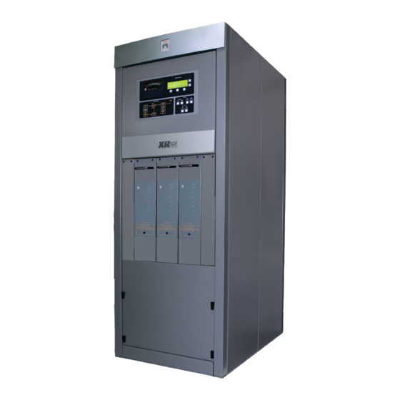
Nautel XR12 Troubleshooting Manual
Hide thumbs
Also See for XR12:
- Installation manual (92 pages) ,
- Operation and maintenance manual (81 pages) ,
- Preinstallation manual (76 pages)

Related Manuals for Nautel XR12


Summary of Contents for Nautel XR12
- Page 1 XR12 Transmitter Troubleshooting Manual Document: XR12-TROUBLESHOOT Issue: 3.1 2014-05-07 Standard Status:...
- Page 3 The comparisons and other information provided in this document have been prepared in good faith based on publicly available information. The reader is encouraged to consult the respective manufacturer's most recent published data for verification. © Copyright 2009 NAUTEL. All rights reserved.
-
Page 5: Table Of Contents
XR12 Troubleshooting Manual Table of contents Contents About this manual About safety xiii Safety precautions Responding to alarms Corrective maintenance Electrostatic protection Identifying an alarm Responding to alarms Removing and reinstalling RF power modules 1-21 Troubleshooting RF power modules 1-25... - Page 6 XR12 Troubleshooting Manual Table of contents RF drive power supply PWB (62 V) (NAPS10C) 2-19 RF power module (NAP34A) 2-20 RF drive buffer PWB (NAPE77A/01) 2-31 Parts Lists Parts information Family tree How to locate information about a specific part Column content OEM code to manufacturer’s cross-reference...
- Page 7 XR12 Troubleshooting Manual Table of contents Locating assembly detail drawings Content of mechanical drawings List of terms Index IX-1 Issue 3.0 2009-07-28 Page vii...
- Page 8 XR12 Troubleshooting Manual Table of contents Page viii Issue 3.0 2009-07-28...
-
Page 9: About This Manual
XR12 Troubleshooting Manual About this manual This manual provides troubleshooting information for the XR12 transmitter. It is intended for use by field technicians. This manual allows the troubleshooting technician to diagnose a fault to the system level, using alarm response procedures, parts lists, wiring lists, and electrical schematics. Electrical schematics and mechanical drawings are included at the end of the manual. - Page 10 The Nautel website provides useful resources to keep you up to date on your XR12. Nautel User Group (NUG) The website includes a special section that customers can log into in order to access the Nautel customer newsletter, product manuals, frequently asked questions (FAQ), information sheets, and information about field upgrades.
-
Page 11: List Of Terms
XR12 Troubleshooting Manual Documentation: online and printed The website’s NUG section provides online access to all the documentation for your XR12. Documentation is provided in Acrobat (PDF) format. You can use the documentation online or print the sections that you need. - Page 12 XR12 Troubleshooting Manual Page xii Issue 3.0 2009-07-28...
-
Page 13: About Safety
XR12 Troubleshooting Manual About safety All Nautel transmitters are designed to meet the requirements of EN60215, Safety Requirements for Radio Transmitters. The philosophy of EN60215 is that the removal of any cover or panel that can only be opened using a tool is a maintenance activity, and that any person performing a maintenance activity is expected to be trained for that activity. - Page 14 XR12 Troubleshooting Manual Lightning hazards Before opening the transmitter and touching internal parts, remove and solidly ground the antenna connection. WARNING: It is not enough to ground the antenna terminal with the antenna still connected. Even a small impedance in the ground strap will result in lethal voltages during a lightning strike.
-
Page 15: Safety Precautions
Personnel must be familiar with the transmitter, so that they can avoid physical danger, and be aware of hazards to themselves and the equipment. Nautel offers a number of training courses covering the basic fundamentals of RF systems and transmitters, and the operation and maintenance of the transmitter. For more information about available courses and schedules, go to the Nautel website at http://www.nautel.com/Training.aspx,... - Page 16 Operation of safety interlocks (if installed) First aid Nautel does not offer first aid training, since the hazards associated with high voltage and RF energy are not specific to the transmitter. However, the customer should provide first aid training to all per- sonnel who have access to the transmitter site.
- Page 17 XR12 Troubleshooting Manual Marking hazards Place warning signs close to any hazardous areas or systems (e.g., the feedline or the antenna system). Make the signs large enough that they cannot be missed. Provide signage in all languages used in the region.
- Page 18 (and to protect the rest of your site equipment and your personnel). For detailed information about lightning protection, see the Nautel Site Preparation Manual, available from your Nautel sales agent, or online from the Nautel website.
- Page 19 XR12 Troubleshooting Manual Earthquake protection If the transmitter site is in a region that experiences any noticeable earthquake activity, take steps to prevent the transmitter from shifting or rocking during an earthquake. Even during minor earthquakes, rocking or movement of the transmitter is likely to damage the feedline connection, and could even cause a catastrophic failure of the ac power feed into the transmitter.
- Page 20 XR12 Troubleshooting Manual Page xx Issue 3.0 2009-07-28...
-
Page 21: Responding To Alarms
Responding to alarms - see page 1-9 • Troubleshooting RF power modules - see page 1-25 If none of the procedures and alarms described in this section address your problem, contact Nautel for assistance. See “Technical support” on page ix... - Page 22 XR12 Troubleshooting Manual Responding to alarms Remote troubleshooting Remote on-air troubleshooting consists of monitoring the transmitter's radiated signal using an on-air monitor, and observing the status of each remote fault alarm indicator. Information obtained from these sources should enable an operator to decide whether an alarm response may be deferred to a more convenient time, an immediate corrective action must be taken, or if a standby transmitter must be enabled (if one is available).
-
Page 23: Electrostatic Protection
XR12 Troubleshooting Manual Responding to alarms Electrostatic protection The transmitter's assemblies contain semiconductor devices that are susceptible to damage from electrostatic discharge. The following precautions must be observed when handling an assembly which contains these devices. CAUTION: Electrostatic energy is produced when two insulating materials are rubbed together. -
Page 24: Identifying An Alarm
XR12 Troubleshooting Manual Responding to alarms Identifying an alarm The best way to identify an alarm is by viewing the transmitter’s front panel. There are several ways to use the front panel to identify the occurrence and origin of a fault: •... - Page 25 4. If the troubleshooting and subsequent replacement of a suspect PWB or RF power module does not remove the fault condition, contact Nautel. NOTE: Before undertaking any troubleshooting, record all GUI meter readings. Then press the STATUS button - if present - on the GUI to see if any other alarms have been registered on the STATUS page .
- Page 26 XR12 Troubleshooting Manual Responding to alarms Table 1.1: Troubleshooting Alarms System Diagram LEDs = SD Remote Interface Alarms =RI System Diagram LEDs Status Description/Action Remote Interface Message Alarms Auto SD: Changeover This event is caused by a fail in the active...
- Page 27 XR12 Troubleshooting Manual Responding to alarms System Diagram LEDs Status Description/Action Remote Interface Message Alarms Int. Serial Fail SD: Exciter This alarm occurs when there is no RI: Exciter Fail communication with the remote interface PWB for 2 seconds. See page 1-19.
- Page 28 XR12 Troubleshooting Manual Responding to alarms System Diagram LEDs Status Description/Action Remote Interface Message Alarms RF Drive P/S SD: Low Voltage Power The RF drive power supply is monitored. This Fail Supply fault will be reported if the voltage exceeds or RI: LVPS Fail falls below the specified limits.
-
Page 29: Responding To Alarms
Reset button on the GUI. See “Navigating from page to page” on page 2-6 the XR12 Operations and Maintenance Manual. If the Alarm does not reset – or if it returns – remove the RF power module for troubleshooting. See “Removing an RF power module”... -
Page 30: Troubleshooting Rf Power Modules
“PM fault” on page 1-9 to troubleshoot. NOTE: A third RF power module is optional for the XR12 transmitter. Ext. interlock open An Ext. Interlock Open alarm indicates an external interlock is open. It will be accompanied by a Shutback alarm. - Page 31 XR12 Troubleshooting Manual Responding to alarms Figure 1.2: XR12 Exciter Panel Assembly (NAE90A – A2) Remote A2A6 Remote Interface PWB Interface A2A2 A2A1 A2A3 Interphase RF Synthesizer Exciter Interface PDM Driver PWB ‘A’ PWB ‘A’ A2A4 A2A5 RF Synthesizer PWB ‘B’...
- Page 32 Section 2, “Installing the power transformer” on page 2-1 of the XR12 Installation Manual. 3. If the transformer taps are correct, the monitoring circuit is suspect. Contact Nautel for troubleshooting information. High B+ voltage A High B+ Voltage alarm is reported when the B+ voltage goes above 380 V, but no other action is taken automatically.
- Page 33 XR12 Troubleshooting Manual Responding to alarms Fan P/S fault The 48 V power supply used for the fans is monitored and will report a fault if the voltage is outside the range of 48 V ± 10%. 1. Check for accompanying alarms in the Status screen. If there is a LVPS Fault , troubleshoot it...
- Page 34 XR12 Troubleshooting Manual Responding to alarms 3. If the input voltages are satisfactory, and the output cannot be adjusted to the required level, suspect the RF drive power supply PWB. 4. If the output voltage is within 62 V ± 10%, and the alarm persists, recalibrate the RF drive power supply to read the measured voltage (see “Calibrating meters”...
- Page 35 This fail is triggered when the product of the B+ (dc) voltage and the dc current is greater than the limit set in software. For the XR12 the threshold is 22 kVA. This fail causes an immediate cutback (power reduction), but not a shutback.
- Page 36 XR12 Troubleshooting Manual Responding to alarms This alarm indicates the PDM duty cycle of exciter B’s modulator drive is too high. Try to reset the alarm. If the alarm persists, proceed to the steps listed in “PDM drive fail”. PDM drive fail This fault indicates that the PDM drive is inoperative.
- Page 37 XR12 Troubleshooting Manual Responding to alarms Auto changeover This event is caused by a fault in the active exciter with the Auto Changeover function enabled. Faults that cause exciter changeovers are: Mod Driver Fail A/B , RF Driver Fail and PDM Drive Fail .
- Page 38 XR12 Troubleshooting Manual Responding to alarms 3. Use an oscilloscope to measure TP2 of the RF drive buffer PWB. The signal should be a 15 volt peak-to-peak square wave at the carrier frequency. If the signal is present, suspect the RF drive buffer PWB.
- Page 39 2. Use an oscilloscope to view TP6 on the interphase PDM driver PWB. If the transmitter is operating at rated power and the audio is clipped (see Figure 1.3), complete “Modulation Peak Limiting” on page 5-5 of the XR12 Operating and Maintenance Manual. Issue 3.0 2009-07-28 Page 1-19...
- Page 40 XR12 Troubleshooting Manual Responding to alarms Figure 1.3: Chopper Control Waveform Audio = 30Hz (AC Coupled) Softstart active The softstart relays are initially open for 1.6 seconds when the transmitter’s power is first turned on. The software should close the relays after 1.6 seconds and clear this alarm. While active, this alarm causes a shutback and inhibits the RF drive and fan power supplies.
- Page 41 XR12 Troubleshooting Manual Responding to alarms The fault may be caused by a weak battery, or a fault in the detection or alarm circuitry on the control/display PWB. If the alarm remains after the battery is replaced, suspect the control/display PWB circuitry.
- Page 42 XR12 Troubleshooting Manual Responding to alarms 6. Grasp the handle on the front of the module, carefully pull the module forward, and grasp the cutout in the top of the module’s rear panel. Carefully lift the module out of the transmitter.
- Page 43 XR12 Troubleshooting Manual Responding to alarms Figure 1.5: XR12 Transmitter - Rear View 3 Packing Bolts Safety Ground Stud Assembly Connection Issue 3.0 2009-07-28 Page 1-23...
- Page 44 XR12 Troubleshooting Manual Responding to alarms Installing an RF power module Refer to Figure 1.4 on page 1-22, and Figure 1.5 on page 1-23 for this procedure. 1. Verify that the RF power module has been tuned to the carrier frequency (see “RF drive...
- Page 45 The following test equipment and cables are required to troubleshoot an RF power module. Power Module Test Kit The power module test kit (Nautel part # 202-5015) is required to use the transmitter’s integral test circuits. It is optionally provided by, or available from, Nautel. It contains: •...
- Page 46 A 5 mm (0.197 in., hex nut driver. The diameter of the outside wall must be less than 7 mm (0.275 in.). • A 2.5 mm (0.098 in.), hex screw driver (Nautel part # HAZ65), included in the ancillary kit. Electrostatic Precautions The RF power module contains semiconductor devices that are susceptible to damage from electrostatic discharge.
- Page 47 XR12 Troubleshooting Manual Responding to alarms Preparation for testing 1. Follow the procedure in “Removing an RF power module” on page 1-21 to remove the power module from the transmitter. 2. Place the RF power module on a suitable work surface in close proximity to the transmitter's RF power module test circuit, so that the RF power module test cable can reach the power module.
- Page 48 XR12 Troubleshooting Manual Responding to alarms PA volts to ground impedance Measure impedance between the PA volts and ground for each RF power block: 1. Measure resistance between terminal H (PA volts input) of each PA input/output PWB and ground, using a digital multimeter.
- Page 49 XR12 Troubleshooting Manual Responding to alarms 7. Restart impedance checks at Step PA volts to B+ impedance Measure impedance between the B+ volts input and the PA volts output for each RF power block: 1. Measure the resistance between terminal H (PA volts) of each PA input/output PWB and its associated B+ fuse.
- Page 50 Figure 1.4 on page 1-22). 2. Connect P4 of the test cable (Nautel part # 202-5010) to J2 of the RF power module to be tested, noting that J2 is the lower connector on the rear of the power module.
- Page 51 XR12 Troubleshooting Manual Responding to alarms NOTE: The RF power module may be connected to the transmitter’s test circuit without turning the transmitter off or interrupting its on-air operation. The host transmitter must be turned on and its RF power stage must be enabled (its RF On LED must be on) for dc voltages to be applied to the RF power module.
- Page 52 XR12 Troubleshooting Manual Responding to alarms check” on page 1-36 to attempt tuning of the RF drive. If the RF Drive LED remains on after tuning, suspect the RF drive control PWB. NOTE: If the test circuits B+ supply fails when the temporary jumper is installed in...
- Page 53 XR12 Troubleshooting Manual Responding to alarms 4. Install a serviceable modulator assembly in each vacant modulator assembly position. 5. Repeat PA volts checks for RF blocks that required repairs. RF amplifier checks Verify the RF amplifiers in each RF power block are functioning and producing an RF output.
- Page 54 XR12 Troubleshooting Manual Responding to alarms 5. Repeat Step 3 Step 4 for the remaining suspect PAs. If any C or G waveform is not satisfactory (rectangular wave, 0 to 24 V, assuming 50% duty cycle), the PA associated with the unsatisfactory waveform is defective and must be replaced (see “RF amplifier assembly...
- Page 55 XR12 Troubleshooting Manual Responding to alarms Figure 1.6: RF Power Module – Left Side RF Drive Tuning Assembly Figure 1.7: RF Drive tuning assembly – cover off RF Drive Tuning Screw Locking Hardware (shown loosened) Issue 3.0 2009-07-28 Page 1-35...
- Page 56 XR12 Troubleshooting Manual Responding to alarms RF drive tuning check Verify the RF drive tuning circuit is functional and the RF drive's tuned circuits are resonant, or can be tuned to resonance at the host transmitter's carrier frequency (f c).
-
Page 57: Exciter Panel And Pwb Removal / Replacement
NOTE: The remote interface PWB and interphase PDM driver PWBs that interconnect with the exciter interface PWB must be removed before the exciter interface PWB can be removed. Figure 1.8: XR12 Exciter Panel Assembly (NAE90A – A2) Panel Mounting Remote Interface PWB... - Page 58 XR12 Troubleshooting Manual Responding to alarms Preparation WARNING: Lethal voltages exist inside the transmitter when the power is turned on. Turn off the power at the source and wait until the green LEDs on the B+ distribution PWB are off before removing any connections or PWBs (see Figure 1.9 on page...
- Page 59 (R59) is not used and requires no adjustment. 4. Install the new interphase PDM driver PWB by reversing Step 1 Step 5. Perform the “Exciter Gain” adjustment procedure on page 5-5 of the XR12 Operating and Maintenance Manual. Issue 3.0 2009-07-28 Page 1-39...
- Page 60 XR12 Troubleshooting Manual Responding to alarms Exciter interface PWB replacement 1. Remove the remote interface PWB (A2A6), both RF synthesizer PWBs (A2A2 and A2A4), and both interphase PDM driver PWBs (A2A3 and A2A5). It may be helpful to gently pry the connectors loose with a screwdriver.
-
Page 61: Rf Drive Buffer Pwb Replacement
XR12 Troubleshooting Manual Responding to alarms RF Drive Buffer PWB replacement WARNING: Lethal voltages exist inside the transmitter when the power is turned on. Turn off the power at the source and wait until the green LEDs on the B+ distribution PWB are off before removing any connections or PWBs (see Figure 1.9 on page... -
Page 62: Distribution Pwb Replacement
XR12 Troubleshooting Manual Responding to alarms 5. Remove the defective PWB from the transmitter. 6. Set the EXCTR A (E1), EXCTR B (E2) and SENSITIVITY (E3) jumpers on the replacement PWB to the same positions as the defective PWB. 7. Reverse... -
Page 63: Rf Drive Power Supply Assembly Replacement
XR12 Troubleshooting Manual Responding to alarms RF Drive Power Supply assembly replacement WARNING: Lethal voltages exist inside the transmitter when the power is turned on. Turn off the power at the source and wait until the green LEDs on the B+ distribution PWB are off before removing any connections or PWBs (see Figure 1.9 on page... -
Page 64: +24 Volt Power Supply Assembly Replacement
XR12 Troubleshooting Manual Responding to alarms 2. Remove the two right-hand blank panels adjacent the RF power module(s). If the optional third RF power module is installed instead of a blank panel, remove it (see“Removing and reinstalling RF power modules” on page 1-21). -
Page 65: Fan Power Supply Assembly Replacement
XR12 Troubleshooting Manual Responding to alarms 5. Remove the assembly from the transmitter. 6. Reverse Step 1 through Step 5 to reinstall the replacement assembly. Fan Power Supply assembly replacement WARNING: Lethal voltages exist inside the transmitter when the power is turned on. -
Page 66: Rf Power Module Assembly Replacement
XR12 Troubleshooting Manual Responding to alarms RF Power Module assembly replacement Each RF power module contains RF amplifier assemblies and modulator assemblies (see Figure 1.11) that can be replaced. Figure 1.11: RF Power Module – Right Side RF Amplifier Assemblies... - Page 67 Responding to alarms Modulator assembly replacement 1. Remove the modulator assembly from RF power module. Use the hex screw driver (Nautel part # HAZ65) from the ancillary kit to remove the modulator assembly’s attaching hardware (four M3 hex head screws) at the rear of the RF power module's heat sink.
- Page 68 1. Remove the RF amplifier assembly from RF power module. Use the hex screw driver (Nautel part # HAZ65) from the ancillary kit to remove the RF amplifier assembly’s attaching hardware (four M3 hex head screws) at the rear of the RF power module's heat sink.
-
Page 69: Detailed Circuit Descriptions
RF power module (NAP34A) - see page 2-20 • RF drive buffer PWB (NAPE77A/01) - see page 2-31 XR12 electrical schematics The descriptions in this section all refer to the XR12 electrical schematics listed in Table 5.1 on page 5-5 of the XR12 Troubleshooting Manual. - Page 70 XR12 Troubleshooting Manual Detailed Circuit Descriptions Alarm threshold circuits Certain parameters that are monitored by the control/display PWB can initiate an alarm indication and appropriate transmitter control if an out of tolerance condition occurs. Ac supply voltage The Ac Power input (J4-21) is an unregulated dc voltage that is proportional to the ac source. The input is filtered and compared to the low ac ref fault threshold on operational amplifier U4C.
- Page 71 XR12 Troubleshooting Manual Detailed Circuit Descriptions Sample monitoring circuits Various parameters are applied to the control/display PWB for local (via the front panel's diagnostic display) and/or external (via the remote interface PWB) monitoring. In most cases, these parameters also have associated alarm detection circuitry, but it is not resident on the control/display PWB.
-
Page 72: Rf Synthesizer Pwb (Nape70C)
XR12 Troubleshooting Manual Detailed Circuit Descriptions Low voltage power supplies Attenuated, buffered samples of all low voltage dc power supplies (+24 V, +15 V, + 5 V and -15 V) are applied to ADCs U9 and U12 for application to the front panel's diagnostic display. - Page 73 2-7). E3 should be set to HIGH PDM mode when used in an XR12 transmitter. The microprocessor determines the value of N and outputs the information at pins 2, 3, 4, 5, 6 and 7. The N divider uses this information as the N dividing factor.
- Page 74 XR12 Troubleshooting Manual Detailed Circuit Descriptions Virtual capacitor Complementary transistor pair U13:A and U13:B, capacitors C50 through C53 and associated components form a virtual capacitor, the value of which is determined by current flow through U13:A. Amplitude and phase of the IPM compensation input controls gain of U13:A, thereby controlling current flow in the transistor and ultimately the virtual capacitance of the IPM correction circuit.
- Page 75 134 kHz (when E3 is set in LOW PDM mode) or between 245 kHz and 276 kHz (when E3 is set in HIGH PDM mode). E3 should be set to HIGH PDM mode when used in an XR12 transmitter.
-
Page 76: Interphase Pdm Driver Pwb (Napm10B)
XR12 Troubleshooting Manual Detailed Circuit Descriptions - E1 in INT position (pins 2 and 3 shorted) - E2 in INT position (pins 2 and 3 shorted) - E4 in EXT position (pins 1 and 2 shorted) The applied RF must be precisely the carrier frequency (f ) and its peak-to-peak voltage (sine or square wave) must be between 5.0 V and 12.0 V. - Page 77 XR12 Troubleshooting Manual Detailed Circuit Descriptions The carrier ref input at J1-2 is a dc voltage directly proportional to the expected RF carrier level squared. When the transmitter is operating at its rated carrier level, the expected carrier ref input at the output of buffer U2A (TP5) is a nominal 4.7 V.
- Page 78 XR12 Troubleshooting Manual Detailed Circuit Descriptions Linear integrator The linear integrator circuit converts the f square wave on its input to a triangular waveform at its output. The triangular waveform has negative and positive voltage excursions of equal amplitude and duration.
- Page 79 XR12 Troubleshooting Manual Detailed Circuit Descriptions Figure 2.1: Timing Diagram for PDM Differential Amplifier Carrier Reference Level Ramp PDM 1 Inverted Carrier Reference Level Ramp PDM 2 PDM2 generator The PDM2 generator consists of U3C, U11B, Q6, Q7, and their associated components. It operates similar to the PDM1 generator except U3C inverts the compensated carrier ref + audio input and applies it to differential comparator U11B's inverting input.
- Page 80 XR12 Troubleshooting Manual Detailed Circuit Descriptions During normal operation, C58 will charge through R67 towards 15 V when the PDM1 output is 15 V (during its 'on time') and CR3 is reversed biased. It will instantly discharge to ground potential, through CR3, when the PDM1 output switches to 0 V (during its 'off time').
-
Page 81: Remote Interface Pwb (Napi83/01A)
SINGLE/DIFF jumper E19 allows the control inputs to be configured to operate from a single-ended or differential input. Refer to “Control and monitoring” section of the XR12 Installation Manual for a detailed description on single-ended versus differential inputs. Issue 3.0 2009-07-28... - Page 82 XR12 Troubleshooting Manual Detailed Circuit Descriptions Remote outputs Remote alarm/status outputs are provided on pins of connectors J2 and J3. A darlington transistor for each alarm/status output provides a negative logic (current-sink-to-ground) output when a logic 'true' (alarm condition or active status) exists. The switching circuit provides an open collector during logic 'false' conditions (non-alarm or non-active status condition) and has no influence on the external monitoring circuit.
- Page 83 XR12 Troubleshooting Manual Detailed Circuit Descriptions Modulation level detector The modulation level detector circuit monitors the on/off times of the Forward Power Sample input (J13-3) for excessive on times. It automatically inhibits a portion of any modulating audio's positive going half-cycle that would cause excessive 'on times' and results in the stress current threshold of the transmitter's RF power amplifier stages being exceeded.
- Page 84 XR12 Troubleshooting Manual Detailed Circuit Descriptions Audio chopper The audio chopper circuit consists of U33D, Q1, and their associated components. It inhibits some portion of positive audio half-cycles that cause modulation peaks/durations that exceed the RF stress current threshold of the transmitter's RF power amplifiers. It accomplishes this by clamping the...
- Page 85 XR12 Troubleshooting Manual Detailed Circuit Descriptions RF monitor and gain setting A sample of the transmitter’s RF output is applied from the RF output filter to the RF Sample input (J7). The front panel GUI, in conjunction with microcontroller U24 and variable gain amplifier U22, provide a means to change the level at the RF MONITOR output (J8).
-
Page 86: Fan Power Supply Pwb (48 V) (Naps30/01)
XR12 Troubleshooting Manual Detailed Circuit Descriptions fan power supply PWB (48 V) (NAPS30/01) See electrical schematic Figure SD-28. The fan power supply PWB is a switch mode power supply that converts the transmitter's B+ voltage to the dc voltage (48 V) used by the cooling fans. -
Page 87: Rf Drive Power Supply Pwb (62 V) (Naps10C)
XR12 Troubleshooting Manual Detailed Circuit Descriptions RF drive power supply PWB (62 V) (NAPS10C) See electrical schematic Figure SD-31. The RF drive power supply PWB is a boost type switching power supply which provides a regulated dc supply voltage for the transmitter's RF drive amplifiers. A nominal +48V supply is applied to the drain of switching FET Q1 through inductor L2. -
Page 88: Rf Power Module (Nap34A)
XR12 Troubleshooting Manual Detailed Circuit Descriptions RF power module (NAP34A) See electrical schematics Figures SD-19 and SD-20. The RF power module is effectively two wideband RF amplifiers for the AM broadcast frequency band (530 - 1710 kHz). The RF power module consists of an RF drive control PWB, an RF drive tuning assembly, a modulator input/output PWB and duplicated assemblies for the two wideband amplifiers. - Page 89 XR12 Troubleshooting Manual Detailed Circuit Descriptions RF drive b+ current limiter The RF drive B+ current limiter is effectively a voltage controlled variable resistor in the RF drive amplifier's B+ voltage path. The magnitude of the control voltage applied to the base of the reference power transistor is determined by circuitry which monitors the RF drive signal's voltage and current.
- Page 90 XR12 Troubleshooting Manual Detailed Circuit Descriptions Latching low rf drive detector Comparator U2D and the peak detector formed by CR8/C7/R6 form the latching low RF drive detector circuit. The RF drive level applied to CR8, which is a sample of the tuned RF drive voltage waveform (from the secondary of T3), is peak detected and applied to U2D's inverting input.
- Page 91 XR12 Troubleshooting Manual Detailed Circuit Descriptions High temp detector Comparator U2B in conjunction with two negative temperature coefficient thermistors mounted on the module's heat sinks, form the high temp detector circuit. The thermistors are connected in parallel and, with R1, form a voltage divider to +15 V. The voltage output of the voltage divider is applied to the inverting input of U2B.
- Page 92 XR12 Troubleshooting Manual Detailed Circuit Descriptions Comparator U6A, inverter U7A and their associated components form the low PA volts detector 'A' circuit. The PDM 1 signal applied to J2-2 is applied through R52 to an average detector formed by R58/C48.
- Page 93 XR12 Troubleshooting Manual Detailed Circuit Descriptions U7A's output will switch to a current-sink-to-ground. A ground potential will be applied to the junction of DS3/CR35 through CR34. The 15 V current source will be removed from J3-11. The PA input/output PWB's RF amplifier fault detector circuit will be reset if it was activated. Its fault detection capability will be inhibited as long as the junction of DS3/CR35 is a ground potential (see “RF amplifier failure detector”...
- Page 94 XR12 Troubleshooting Manual Detailed Circuit Descriptions • Be applied to the cathodes of CR26, CR28, CR40 and CR42 as a logic true reset command. The PDM input to all four low PA volts detectors will effectively be clamped to ground for the duration of the reset pulse.
- Page 95 XR12 Troubleshooting Manual Detailed Circuit Descriptions Modulator input/output pwb The modulator input/output PWB interfaces the B+ VDC, PDM, and gate bias drive inputs and the PDM (B+) outputs of the four modulator assemblies. The B+ voltage for each modulator is separately fused at 20 A.
- Page 96 XR12 Troubleshooting Manual Detailed Circuit Descriptions Modulator filter See electrical schematic Figure SD-20. An inductor, L/C components on the modulator filter and the input capacitance of two RF amplifiers form a low pass filter for the modulator's PDM (B+) output. The filter is connected as a multi-pole, tuned filter that shunts the PDM frequency component of the PDM (B+) input to ground.
- Page 97 XR12 Troubleshooting Manual Detailed Circuit Descriptions Normally, the RF drive currents will be balanced, there will be minimal voltage across T1's secondary and the voltage applied to Q1's gate will not be sufficient to forward bias it. Q1 will be turned off and the RF Amp Fail signal will be logic false since 24 V is being applied from a pull-up resistor in the RF drive control PWB's crowbar switch circuit.
- Page 98 XR12 Troubleshooting Manual Detailed Circuit Descriptions Figure 2.2: Simplified Principles of Class ‘D’ Operation Simple Class 'D' Operation If the switch is opened and closed with a 50% duty cycle, a square wave at the switching frequency results at the filter input.
-
Page 99: Rf Drive Buffer Pwb (Nape77A/01)
XR12 Troubleshooting Manual Detailed Circuit Descriptions RF drive buffer PWB (NAPE77A/01) See electrical schematic Figure SD-30. The 0 - 15 V RF carrier frequency signals generated by the RF synthesizer PWBs are applied to the RF Drive A (J1) and B (J2) inputs. The active RF Drive signal, as selected by relay K1, is applied to MOSFET drivers U2A through U5A . - Page 100 XR12 Troubleshooting Manual Detailed Circuit Descriptions Page 2-32 Issue 3.0 2009-07-28...
-
Page 101: Parts Lists
• Follow the family tree branches to the block that represents the lowest level assembly assigned a Nautel nomenclature. Then refer to the parts list at the end of this section. Issue 3.0 2009-07-28 Page 3-1... -
Page 102: Column Content
Nautel part (e.g., 202-8005-01) • optional kits that are assigned a numbered Nautel part. To obtain the full reference designation for a specific part the Nautel configuration control number must be located in the family tree (see Figure 3.1 on page 3-6) to include the reference designation of all higher level assemblies. -
Page 103: Oem Code To Manufacturer's Cross-Reference
The listed number is Nautel's usual or preferred choice. The use of this number does not restrict Nautel from selecting and using commercial equivalents during manufacture, where their use will not degrade circuit operation or reliability. -
Page 104: Common Abbreviations/Acronyms
XR12 Troubleshooting Manual Parts Lists Common abbreviations/acronyms The following abbreviations/acronyms may appear in the Description of Part column: • Denotes item is designed to be installed using Surface Mount Technology. • Denotes item is a Mass Termination Assembly connector. •... - Page 105 XR12 Troubleshooting Manual Parts Lists Table 3.1: OEM Codes / Manufacturers OEM Code Manufacturer OEM Code Manufacturer 1FN41 Atmel Corporation 59124 KOA Speer Electronics Inc. 1JRT7 Epson Electronics American Inc. 5Y407 Phoenix Contact Inc. 1KK13 ITT Industries Incorporated 61529 Airmat Corporation...
- Page 106 XR12 Troubleshooting Manual Parts Lists Figure 3.1: XR12 Family Tree XR12 12KW AM BROADCAST TRANSMITTER NARA42B (SEE PART NUMBER INDEX FOR ALL SUB-ASSEMBLIES) CONTROL PANEL EXCITER PANEL NAC113B NAE90A A1A1 A1A2 A2A1 A2A2 CONTROL/DISPLAY PWB DYNAMIC CARRIER CONTROL PWB EXCITER INTERFACE PWB...
- Page 107 XR12 Troubleshooting Manual Parts Lists Figure 3.2: NAP34A RF Power Module Family Tree RF POWER MODULE NAP34A RF DRIVE CONTROL PWB RF TUNING ASSY MODULATOR ASSY NAPC150A NOT USED NAX180C NASM07H MODULATOR ASSY MODULATOR FILTER ASSY MODULATOR FILTER ASSY PA INPUT/OUTPUT PWB...
- Page 108 XR12 Troubleshooting Manual Parts Lists Page 3-8 Issue 3.0 2009-07-28...
- Page 109 176-1038-03 Coil Assy REFDES DESCRIPTION NAUTEL # VENDOR # OEM CODE Resistor, Wirewound, 3.9 Ohms, 5%, 5W RT34 PW-5 3.9 5% 75042 Resistor, Wirewound, 3.9 Ohms, 5%, 5W RT34 PW-5 3.9 5% 75042 176-1065-04 PA Input/Output PWB REFDES DESCRIPTION NAUTEL #...
- Page 110 176-1185 Modulator Filter PWB Assy REFDES DESCRIPTION NAUTEL # VENDOR # OEM CODE Capacitor, Metal, Polyprop,.22uF, 5%, 630V CAP50 2222-378-64224 BC 56699 COMP Capacitor, Metal, Polyprop,.22uF, 5%, 630V CAP50 2222-378-64224 BC 56699 COMP Capacitor,Metal,Polyprop,.27uF,5%,630V CNP45 2222-378-64274 56699 Capacitor,Metal,Polyprop,.012uF,5%,1000V CNP46 2222-378-74123...
- Page 111 176-6148-34 Power Probe PWB Assy REFDES DESCRIPTION NAUTEL # VENDOR # OEM CODE Capacitor, Mica, Dipped, 5600pF 2% 500V CAP14 CM07FD562G03 14655 Capacitor, Mica, Dipped, 3300pF 2% 500V CCD18 CM06FD332G03 14655 Not Used NOT USED 37338 Capacitor, Tantalum, Dipped, 10uF, 35V...
- Page 112 Continued from previous page 176-6148-34 Power Probe PWB Assy REFDES DESCRIPTION NAUTEL # VENDOR # OEM CODE Resistor, MF, 100 Ohms, 1PC 1/4W RAB13 MF1/4DL1000F 59124 Resistor, Film, 100 Ohms, 5%2W RBP07 GS-3, 100 OHMS 75042 Switch, 8-Position, Piano, DIP, 1PST...
- Page 113 194-1012 Capacitor Bracket Assy REFDES DESCRIPTION NAUTEL # VENDOR # OEM CODE Capacitor, Metal,Polyprop, 5uF +/-20% 600V CT40 734G505X0600 DEARBO Capacitor, Metal,Polyprop, 5uF +/-20% 600V CT40 734G505X0600 DEARBO Capacitor, Metal,Polyprop, 5uF +/-20% 600V CT40 734G505X0600 DEARBO Capacitor, Metal,Polyprop, 5uF +/-20% 600V...
- Page 114 202-2004-02 Control Display Assy REFDES DESCRIPTION NAUTEL # VENDOR # OEM CODE Control Display PWB Assy NAPC147D 195-2050-04 37338 Mod, UDDS01 202-2020 202-2020 37338 202-6045 Static Drain Choke PWB Assy REFDES DESCRIPTION NAUTEL # VENDOR # OEM CODE Conn, Post Shunt, 2 Pos, .10 Centreline...
- Page 115 202-7005-03 Cable Assy, XR12 Pwr/Sply REFDES DESCRIPTION NAUTEL # VENDOR # OEM CODE MTA, Standard Dust Cover, 12 pin JU04 1-640551-2 09482 MTA, Keyed Closed End Housing,12pin,22AWG JU26 1-644463-2 00779 Conn, Socket, D-Sub, HDP-20, 25 pin JR38 205207-1 09482 Conn, Lock Screw, D-Sub, Male...
- Page 116 37338 Fan, Modified 200-5030-01 200-5030-01 37338 Conn, Pin, Header, 3-PinMate'n Lock JT64 350767-1 00779 202-8005-01 Cableform, XR12 REFDES DESCRIPTION NAUTEL # VENDOR # OEM CODE Conn, Recept, Ribbon Cable, 40 pin JP51 746288-9 00779 Conn, Socket, D-Sub, HDP-20, 25 pin...
- Page 117 202-8050 Cableform, Power ModuleInterface, 40in REFDES DESCRIPTION NAUTEL # VENDOR # OEM CODE Conn, Clamp, Strain Relief, Size 17, Lg JE13 206322-1 09482 Conn, Plug, Size 17-28 JT08 205839-3 09482 Conn, Plug, 3-Pin, Mate-N-Lok JT50 350766-1 00779 Conn, Plug, D-Sub, 25 pin, HDP-20...
- Page 118 NAA51A/00 RF Amplifier Assy, Basic REFDES DESCRIPTION NAUTEL # VENDOR # OEM CODE CR01 Diode, Power Rectifier, 4A, Ultra Fast QM22 MUR460 04713 CR02 Diode, Power Rectifier, 4A, Ultra Fast QM22 MUR460 04713 CR03 Diode, Power Rectifier, 4A, Ultra Fast...
- Page 119 NAFP103/05 Forward/Reflected Power Probe,XR12/XR6/XR3 REFDES DESCRIPTION NAUTEL # VENDOR # OEM CODE Power Probe PWB Assy 176-6148-34 176-6148-34 37338 Capacitor, Ceramic, 50pF +10%15000V CCG42 T500K99COGW8570 56699 Conn, Coax, BNC, Recept, 50ohm JDP26 UG1094/U 02660 Conn, Coax, BNC, Recept, 50ohm JDP26...
- Page 120 NAP34A RF Power Module Assy,XR Series REFDES DESCRIPTION NAUTEL # VENDOR # OEM CODE RF Drive Control PWB Assy NAPC150A 202-1150-02 37338 Not Used NOT USED 37338 RF Tuning Assy (Manual) NAX180C 184-1150-03 37338 Modulator Assy NASM07H 176-1020-08 37338 Modulator Assy...
- Page 121 Continued from previous page NAP34A RF Power Module Assy,XR Series REFDES DESCRIPTION NAUTEL # VENDOR # OEM CODE Resistor, Film, 330K Ohms, 2PC 1/2W RAP19 RL20S334G 35005 Resistor, Film, 330K Ohms, 2PC 1/2W RAP19 RL20S334G 35005 Resistor, Film, 330K Ohms, 2PC 1/2W...
- Page 122 NAPC147D Control Display PWB Assy REFDES DESCRIPTION NAUTEL # VENDOR # OEM CODE BT01 Battery, Lithium, 3V,20mm Coin Cell BBLT01 CR2032 PANAS C001 Cap,SMT,Ceramic,0.01uF,10%,50V,X7R,0603 CCFS04 C0603C103K5RAC 31433 C002 Cap,SMT,Ceramic,0.01uF,10%,50V,X7R,0603 CCFS04 C0603C103K5RAC 31433 C003 Cap,SMT,Ceramic,0.01uF,10%,50V,X7R,0603 CCFS04 C0603C103K5RAC 31433 C004 Cap,SMT,Ceramic,0.01uF,10%,50V,X7R,0603 CCFS04...
- Page 123 Continued from previous page NAPC147D Control Display PWB Assy REFDES DESCRIPTION NAUTEL # VENDOR # OEM CODE C039 Cap,SMT,Ceramic,0.1uF,10%,50V,X7R,0805 CCFS07 C0805C104K5RAC 31433 C040 Cap,SMT,Ceramic,0.1uF,10%,50V,X7R,0805 CCFS07 C0805C104K5RAC 31433 C041 Cap,SMT,Ceramic,0.1uF,10%,50V,X7R,0805 CCFS07 C0805C104K5RAC 31433 C042 Cap,SMT,Ceramic,0.1uF,10%,50V,X7R,0805 CCFS07 C0805C104K5RAC 31433 C043 Cap,SMT,Ceramic,0.1uF,10%,50V,X7R,0805 CCFS07...
- Page 124 Continued from previous page NAPC147D Control Display PWB Assy REFDES DESCRIPTION NAUTEL # VENDOR # OEM CODE C078 Cap,SMT,Ceramic,0.1uF,10%,50V,X7R,0805 CCFS07 C0805C104K5RAC 31433 C079 Cap,SMT,Ceramic,0.1uF,10%,50V,X7R,0805 CCFS07 C0805C104K5RAC 31433 C080 Cap,SMT,Ceramic,0.1uF,10%,50V,X7R,0805 CCFS07 C0805C104K5RAC 31433 C081 Cap,SMT,Ceramic,0.1uF,10%,50V,X7R,0805 CCFS07 C0805C104K5RAC 31433 C082 Cap,SMT,Ceramic,0.01uF,10%,50V,X7R,0603 CCFS04...
- Page 125 Continued from previous page NAPC147D Control Display PWB Assy REFDES DESCRIPTION NAUTEL # VENDOR # OEM CODE C117 Cap,SMT,Ceramic,0.01uF,10%,50V,X7R,0603 CCFS04 C0603C103K5RAC 31433 C118 Cap,SMT,Ceramic,0.01uF,10%,50V,X7R,0603 CCFS04 C0603C103K5RAC 31433 C119 Cap,SMT,Ceramic,0.1uF,10%,50V,X7R,0805 CCFS07 C0805C104K5RAC 31433 C120 Cap,SMT,Tantalum,10uF,10%,35V,2917 CTFS03 T494D106K035AS 31433 C121 Cap,SMT,Ceramic,0.01uF,10%,50V,X7R,0603 CCFS04...
- Page 126 Continued from previous page NAPC147D Control Display PWB Assy REFDES DESCRIPTION NAUTEL # VENDOR # OEM CODE C156 Cap,SMT,Ceramic,0.01uF,10%,50V,X7R,0603 CCFS04 C0603C103K5RAC 31433 C157 Cap,SMT,Ceramic,0.1uF,10%,50V,X7R,0805 CCFS07 C0805C104K5RAC 31433 C158 Cap,SMT,Tantalum,10uF,10%,35V,2917 CTFS03 T494D106K035AS 31433 C159 Cap,SMT,Ceramic,0.01uF,10%,50V,X7R,0603 CCFS04 C0603C103K5RAC 31433 C160 Cap,SMT,Ceramic,0.1uF,10%,50V,X7R,0805 CCFS07...
- Page 127 Continued from previous page NAPC147D Control Display PWB Assy REFDES DESCRIPTION NAUTEL # VENDOR # OEM CODE Conn, Header,Square Post,Gold,Dual,40-pin JF47 4-102973-0 09482 MTA, Keyed Square Post HeaderAssy, 4 pin JU25 647123-4 00779 Inductor, SMT, Choke, 600ohms,2A, 0805 LCFS01 ILHB0805RK601V...
- Page 128 Continued from previous page NAPC147D Control Display PWB Assy REFDES DESCRIPTION NAUTEL # VENDOR # OEM CODE R015 Resistor,SMT,MF,100ohms,1%,1/10W,0603 RFFS26 RK73H1JLTD1000F 59124 R016 Resistor,SMT,MF,4750ohms,1%,1/10W,0603 RFFS46 RK73H1JLTD4751F 59124 R017 Resistor,SMT,MF,475Kohms,1%,1/10W,0603 RFFS70 RK73H1JLTD4753F 59124 R018 Resistor,SMT,MF,475Kohms,1%,1/10W,0603 RFFS70 RK73H1JLTD4753F 59124 R019 Resistor,SMT,MF,10.0Kohms,1%,1/10W,0603 RFFS50...
- Page 129 Continued from previous page NAPC147D Control Display PWB Assy REFDES DESCRIPTION NAUTEL # VENDOR # OEM CODE R054 Resistor,SMT,MF,475Kohms,1%,1/10W,0603 RFFS70 RK73H1JLTD4753F 59124 R055 Resistor,SMT,MF,475Kohms,1%,1/10W,0603 RFFS70 RK73H1JLTD4753F 59124 R056 Resistor,SMT,MF,475Kohms,1%,1/10W,0603 RFFS70 RK73H1JLTD4753F 59124 R057 Resistor,SMT,MF,10.0Kohms,1%,1/10W,0603 RFFS50 RK73H1JLTD1002F 59124 R058 Resistor,SMT,MF,1000ohms,1%,1/10W,0603 RFFS38...
- Page 130 Continued from previous page NAPC147D Control Display PWB Assy REFDES DESCRIPTION NAUTEL # VENDOR # OEM CODE R093 Resistor,SMT,MF,10.0Kohms,1%,1/10W,0603 RFFS50 RK73H1JLTD1002F 59124 R094 Resistor,SMT,MF,1000ohms,1%,1/10W,0603 RFFS38 RK73H1JLTD1001F 59124 R095 Resistor,SMT,MF,68.1Kohms,1%,1/10W,0603 RFFS60 RK73H1JLTD6812F 59124 R096 Resistor,SMT,MF,1000ohms,1%,1/10W,0603 RFFS38 RK73H1JLTD1001F 59124 R097 Resistor,SMT,MF,10.0Kohms,1%,1/10W,0603 RFFS50...
- Page 131 Continued from previous page NAPC147D Control Display PWB Assy REFDES DESCRIPTION NAUTEL # VENDOR # OEM CODE R132 Resistor,SMT,MF,22.1Kohms,1%,1/10W,0603 RFFS54 RK73H1JLTD2212F 59124 R133 Resistor,SMT,MF,1820ohms,1%,1/10W,0603 RFFS41 RK73H1JLTD1821F 59124 R134 Resistor,SMT,MF,12.1Kohms,1%,1/10W,0603 RFFS51 RK73H1JLTD1212F 59124 R135 Resistor,SMT,MF,10.0Kohms,1%,1/10W,0603 RFFS50 RK73H1JLTD1002F 59124 R136 Resistor,SMT,MF,10.0Kohms,1%,1/10W,0603 RFFS50...
- Page 132 Continued from previous page NAPC147D Control Display PWB Assy REFDES DESCRIPTION NAUTEL # VENDOR # OEM CODE R171 Resistor,SMT,MF,2210ohms,1%,1/10W,0603 RFFS42 RK73H1JLTD2211F 59124 R172 Resistor,SMT,MF,4750ohms,1%,1/10W,0603 RFFS46 RK73H1JLTD4751F 59124 R173 Resistor,SMT,MF,100ohms,1%,1/10W,0603 RFFS26 RK73H1JLTD1000F 59124 R174 Resistor,SMT,MF,4750ohms,1%,1/10W,0603 RFFS46 RK73H1JLTD4751F 59124 R175 Resistor,SMT,MF,100ohms,1%,1/10W,0603 RFFS26...
- Page 133 Continued from previous page NAPC147D Control Display PWB Assy REFDES DESCRIPTION NAUTEL # VENDOR # OEM CODE R210 Resistor,SMT,MF,100ohms,1%,1/10W,0603 RFFS26 RK73H1JLTD1000F 59124 R211 Resistor,SMT,MF,4750ohms,1%,1/10W,0603 RFFS46 RK73H1JLTD4751F 59124 R212 Resistor,SMT,MF,100ohms,1%,1/10W,0603 RFFS26 RK73H1JLTD1000F 59124 R213 Resistor,SMT,MF,4750ohms,1%,1/10W,0603 RFFS46 RK73H1JLTD4751F 59124 R214 Resistor,SMT,MF,100ohms,1%,1/10W,0603 RFFS26...
- Page 134 Continued from previous page NAPC147D Control Display PWB Assy REFDES DESCRIPTION NAUTEL # VENDOR # OEM CODE R249 Resistor,SMT,MF,1000ohms,1%,1/10W,0603 RFFS38 RK73H1JLTD1001F 59124 R250 Resistor,SMT,MF,100ohms,1%,1/10W,0603 RFFS26 RK73H1JLTD1000F 59124 R251 Resistor,SMT,MF,10.0Kohms,1%,1/10W,0603 RFFS50 RK73H1JLTD1002F 59124 R252 Resistor,SMT,MF,3920ohms,1%,1/10W,0603 RFFS45 RK73H1JLTD3921F 59124 R253 Resistor,SMT,MF,100Kohms,1%,1/10W,0603 RFFS62...
- Page 135 Continued from previous page NAPC147D Control Display PWB Assy REFDES DESCRIPTION NAUTEL # VENDOR # OEM CODE IC,SMT,2.5V Reference,0.1%,SOT-23-6 UX83 LT1790BIS6- 64155 2.5(STATIC) IC,SMT,Opamp,Quad,Single Supply,SOIC-14 ULAS01 MC33074AD(STATIC) 04713 IC,SMT,Opamp,Quad,Single Supply,SOIC-14 ULAS01 MC33074AD(STATIC) 04713 IC,SMT,CMOS,Octal Flip Flop,SOIC-20 UDLS01 SN74AHC574DW(STA 01295 TIC) IC,SMT,Trans Array, 7 Darl.,SOIC-16...
- Page 136 NAPC150A RF Drive Control PWB Assy REFDES DESCRIPTION NAUTEL # VENDOR # OEM CODE Not Used NOT USED 37338 Capacitor, Ceramic, 0.47uF 10% 50V CCG09 CKR06BX474KRV 56289 Capacitor, Ceramic, 0.1uF 10%100V CCG07 CKR06BX104KRV 56289 Capacitor, Tantalum, Dipped, 10uF, 35V CCP36...
- Page 137 Continued from previous page NAPC150A RF Drive Control PWB Assy REFDES DESCRIPTION NAUTEL # VENDOR # OEM CODE Not Used NOT USED 37338 Not Used NOT USED 37338 Not Used NOT USED 37338 Not Used NOT USED 37338 Capacitor, Tantalum, Dipped, 10uF, 35V...
- Page 138 Continued from previous page NAPC150A RF Drive Control PWB Assy REFDES DESCRIPTION NAUTEL # VENDOR # OEM CODE CR18 Diode, Zener Transient Supressor, 20V QI29 P6KE20CA 07263 CR19 Not Used NOT USED 37338 CR20 Not Used NOT USED 37338 CR21...
- Page 139 Continued from previous page NAPC150A RF Drive Control PWB Assy REFDES DESCRIPTION NAUTEL # VENDOR # OEM CODE CR57 Diode, General Purpose, 200V,0.1A QAP29 1N4938 07263 CR58 Diode, General Purpose, 200V,0.1A QAP29 1N4938 07263 CR59 Diode, General Purpose, 200V,0.1A QAP29...
- Page 140 Continued from previous page NAPC150A RF Drive Control PWB Assy REFDES DESCRIPTION NAUTEL # VENDOR # OEM CODE Transistor, FET, N Channel, 100V, 8A QR13 IRF520(STATIC) 81483 Transistor, FET, N Channel, 100V, 8A QR13 IRF520(STATIC) 81483 Transistor, PNP, Switch/Amplifier QA14...
- Page 141 Continued from previous page NAPC150A RF Drive Control PWB Assy REFDES DESCRIPTION NAUTEL # VENDOR # OEM CODE R049 Resistor, MF, 2.21K Ohms, 1PC1/4W RAB29 MF1/4DL2211F 59124 R050 Resistor, Film, 150K Ohms, 2PC 1/2W RD21 RL20S154G 35005 R051 Resistor, Film, 150K Ohms, 2PC 1/2W...
- Page 142 Continued from previous page NAPC150A RF Drive Control PWB Assy REFDES DESCRIPTION NAUTEL # VENDOR # OEM CODE R088 Resistor, MF, 10.0K Ohms, 1PC1/4W RAB37 MF1/4DL1002F 59124 R089 Resistor, MF, 10.0K Ohms, 1PC1/4W RAB37 MF1/4DL1002F 59124 R090 Resistor, MF, 2.21K Ohms, 1PC1/4W...
- Page 143 Continued from previous page NAPC150A RF Drive Control PWB Assy REFDES DESCRIPTION NAUTEL # VENDOR # OEM CODE IC, Comparator, Quad UL02 MC3302L(STATIC) 04713 Not Used NOT USED 37338 XE01 Not Used NOT USED 37338 XF01 Fuseholder, PWB Mount, Type 3AG...
- Page 144 NAPE70C RF Synthesizer PWB Assy REFDES DESCRIPTION NAUTEL # VENDOR # OEM CODE Not Used NOT USED 37338 Capacitor, Ceramic, 0.1uF 10%100V CCG07 CKR06BX104KRV 56289 Capacitor, Ceramic, 0.1uF 10%100V CCG07 CKR06BX104KRV 56289 Capacitor, Tantalum, 2.2uF 10PC 20V CCP16 CSR13E225KM 56289 Capacitor, Ceramic, 0.01uF 10% 100V...
- Page 145 Continued from previous page NAPE70C RF Synthesizer PWB Assy REFDES DESCRIPTION NAUTEL # VENDOR # OEM CODE Capacitor, Tantalum, Dipped, 10uF, 35V CCP36 T351G106K035AT(Ro 96095 HS) KEMET Capacitor, Tantalum, Dipped, 10uF, 35V CCP36 T351G106K035AT(Ro 96095 HS) KEMET Capacitor, Ceramic, 0.1uF 10%100V...
- Page 146 Continued from previous page NAPE70C RF Synthesizer PWB Assy REFDES DESCRIPTION NAUTEL # VENDOR # OEM CODE Inductor, Moulded, Shielded, 1.8uH LAP28 IMS-5-1.8UH+/-10% 35005 Inductor, Choke, 2.5 Turns, JMtl LA16 82-152-J 33062 Inductor, Choke, 2.5 Turns, JMtl LA16 82-152-J 33062 Inductor, Choke, 2.5 Turns, JMtl...
- Page 147 Continued from previous page NAPE70C RF Synthesizer PWB Assy REFDES DESCRIPTION NAUTEL # VENDOR # OEM CODE Not Used NOT USED 37338 Resistor, MF, 1.50K Ohms, 1PC1/4W RAB27 MF1/4DL1501F 59124 Resistor, MF, 100 Ohms, 1PC 1/4W RAB13 MF1/4DL1000F 59124 Resistor, MF, 10.0K Ohms, 1PC1/4W...
- Page 148 Continued from previous page NAPE70C RF Synthesizer PWB Assy REFDES DESCRIPTION NAUTEL # VENDOR # OEM CODE IC, CMOS, 48-bit DDS UT58 AD9852ASQ(STATIC) 45496 IC, CMOS, Synchronous Counter UT56 74ACT163PC(STATIC) 07263 IC, CMOS, Synchronous Counter UT56 74ACT163PC(STATIC) 07263 IC, CMOS, Hex Inverter...
- Page 149 NAPE77A/01 RF Driver Buffer PWB Assy REFDES DESCRIPTION NAUTEL # VENDOR # OEM CODE Capacitor, Ceramic, 0.022uF 10% 100V CCG05 CKR06BX223KRV 56289 Capacitor, Ceramic, 0.1uF 10%100V CCG07 CKR06BX104KRV 56289 Not Used NOT USED 37338 Capacitor, Ceramic, 0.1uF 10%100V CCG07 CKR06BX104KRV 56289 Capacitor, Ceramic, 0.1uF 10%100V...
- Page 150 Continued from previous page NAPE77A/01 RF Driver Buffer PWB Assy REFDES DESCRIPTION NAUTEL # VENDOR # OEM CODE CR01 Diode, Schottky QR15 MBD301(STATIC) 04713 CR02 Diode, General Purpose, 200V,0.1A QAP29 1N4938 07263 Conn, Post Shunt, 2 Pos, .10 Centreline JQ15...
- Page 151 Continued from previous page NAPE77A/01 RF Driver Buffer PWB Assy REFDES DESCRIPTION NAUTEL # VENDOR # OEM CODE Resistor, Film, 10 Ohms, 5%, 2W RBP01 GS-3, 10 OHMS 75042 Not Used NOT USED 37338 Not Used NOT USED 37338 Not Used...
- Page 152 NAPI47B Modulator Input Output PWB Assy REFDES DESCRIPTION NAUTEL # VENDOR # OEM CODE Capacitor, Ceramic, 1.0uF 10%50V CCG10 CKR06BX105KRV 56289 Capacitor, Ceramic, 0.022uF 10% 100V CCG05 CKR06BX223KRV 56289 Capacitor, Ceramic, 0.022uF 10% 100V CCG05 CKR06BX223KRV 56289 Capacitor, Ceramic, 0.022uF 10% 100V...
- Page 153 Continued from previous page NAPI47B Modulator Input Output PWB Assy REFDES DESCRIPTION NAUTEL # VENDOR # OEM CODE Conn, Plug, D-Sub, 9 pin, PWBMt JQ33 K22-E9P-NJ 31781 Transistor, NPN, TO-220, 100V QS19 TIP31C 04713 Transistor, PNP, TO-220, 100V QS18 TIP32C...
- Page 154 NAPI82A Exciter Interface PWB,XRSeries REFDES DESCRIPTION NAUTEL # VENDOR # OEM CODE Capacitor, Ceramic, 0.1uF 10%100V CCG07 CKR06BX104KRV 56289 Capacitor, Ceramic, 0.1uF 10%100V CCG07 CKR06BX104KRV 56289 Capacitor, Ceramic, 0.1uF 10%100V CCG07 CKR06BX104KRV 56289 Capacitor, Ceramic, 0.01uF 10% 100V CCG04 CKR05BX103KRV...
- Page 155 Continued from previous page NAPI82A Exciter Interface PWB,XRSeries REFDES DESCRIPTION NAUTEL # VENDOR # OEM CODE Conn, Socket, D-Sub, 25 pin, PWB Mt JS13 K22-B25S-NJ 22421 Conn, Header, Ribbon Cbl, 40 pin JP52 499910-9 00779 Conn, Header, Ribbon Cbl, 40 pin...
- Page 156 Continued from previous page NAPI82A Exciter Interface PWB,XRSeries REFDES DESCRIPTION NAUTEL # VENDOR # OEM CODE Resistor, MF, 4.75K Ohms, 1PC1/4W RAB33 MF1/4DL4751F 59124 Resistor, MF, 10.0K Ohms, 1PC1/4W RAB37 MF1/4DL1002F 59124 Resistor, MF, 10.0K Ohms, 1PC1/4W RAB37 MF1/4DL1002F 59124...
- Page 157 NAPI83/01A Remote Interface PWB,XR Series REFDES DESCRIPTION NAUTEL # VENDOR # OEM CODE C001 Cap,SMT,Ceramic,0.1uF,10%,50V,X7R,0805 CCFS07 C0805C104K5RAC 31433 C002 Cap,SMT,Tantalum,10uF,10%,16V,1411 CTFS01 T494B106K016AS 31433 C003 Cap,SMT,Ceramic,0.1uF,10%,50V,X7R,0805 CCFS07 C0805C104K5RAC 31433 C004 Cap,SMT,Tantalum,10uF,10%,35V,2917 CTFS03 T494D106K035AS 31433 C005 Cap,SMT,Ceramic,0.1uF,10%,50V,X7R,0805 CCFS07 C0805C104K5RAC 31433 C006 Cap,SMT,Ceramic,0.1uF,10%,50V,X7R,0805...
- Page 158 Continued from previous page NAPI83/01A Remote Interface PWB,XR Series REFDES DESCRIPTION NAUTEL # VENDOR # OEM CODE C040 Cap,SMT,Ceramic,0.1uF,10%,50V,X7R,0805 CCFS07 C0805C104K5RAC 31433 C041 Cap,SMT,Ceramic,0.1uF,10%,50V,X7R,0805 CCFS07 C0805C104K5RAC 31433 C042 Cap,SMT,Ceramic,0.1uF,10%,50V,X7R,0805 CCFS07 C0805C104K5RAC 31433 C043 Cap,SMT,Ceramic,0.1uF,10%,50V,X7R,0805 CCFS07 C0805C104K5RAC 31433 C044 Cap,SMT,Ceramic,0.1uF,10%,50V,X7R,0805 CCFS07...
- Page 159 Continued from previous page NAPI83/01A Remote Interface PWB,XR Series REFDES DESCRIPTION NAUTEL # VENDOR # OEM CODE C079 Cap,SMT,Ceramic,0.1uF,10%,50V,X7R,0805 CCFS07 C0805C104K5RAC 31433 C080 Cap,SMT,Ceramic,0.1uF,10%,50V,X7R,0805 CCFS07 C0805C104K5RAC 31433 C081 Cap,SMT,Ceramic,0.1uF,10%,50V,X7R,0805 CCFS07 C0805C104K5RAC 31433 C082 Cap,SMT,Ceramic,0.1uF,10%,50V,X7R,0805 CCFS07 C0805C104K5RAC 31433 C083 Cap,SMT,Ceramic,0.1uF,10%,50V,X7R,0805 CCFS07...
- Page 160 Continued from previous page NAPI83/01A Remote Interface PWB,XR Series REFDES DESCRIPTION NAUTEL # VENDOR # OEM CODE C119 Cap,SMT,Ceramic,0.1uF,10%,50V,X7R,0805 CCFS07 C0805C104K5RAC 31433 C120 Not Used NOT USED 37338 C121 Cap,SMT,Tantalum,10uF,10%,35V,2917 CTFS03 T494D106K035AS 31433 C123 Cap,SMT,Ceramic,0.1uF,10%,50V,X7R,0805 CCFS07 C0805C104K5RAC 31433 C124 Cap,SMT,Ceramic,0.1uF,10%,50V,X7R,0805...
- Page 161 Continued from previous page NAPI83/01A Remote Interface PWB,XR Series REFDES DESCRIPTION NAUTEL # VENDOR # OEM CODE CR12 Diode,SMT,Switching,250V,0.2A,SOD-323 QDRS01 BAS21HT1(STATIC) 04713 CR13 Diode,SMT,Switching,250V,0.2A,SOD-323 QDRS01 BAS21HT1(STATIC) 04713 CR14 Diode,SMT,Switching,250V,0.2A,SOD-323 QDRS01 BAS21HT1(STATIC) 04713 CR15 Diode,SMT,Switching,250V,0.2A,SOD-323 QDRS01 BAS21HT1(STATIC) 04713 CR16 Diode,SMT,Switching,250V,0.2A,SOD-323 QDRS01...
- Page 162 Continued from previous page NAPI83/01A Remote Interface PWB,XR Series REFDES DESCRIPTION NAUTEL # VENDOR # OEM CODE Not Used NOT USED 37338 Not Used NOT USED 37338 Not Used NOT USED 37338 Not Used NOT USED 37338 Not Used NOT USED...
- Page 163 Continued from previous page NAPI83/01A Remote Interface PWB,XR Series REFDES DESCRIPTION NAUTEL # VENDOR # OEM CODE Transistor,SMT,NPN,Switch/Amp,SOT-23 QBNS01 MMBT4401LT1(STATI 04713 Transistor,SMT,NPN,Switch/Amp,SOT-23 QBNS01 MMBT4401LT1(STATI 04713 Transistor,SMT,MOSFET,N-Channel,60V,115mA,SOT- QN53 2N7002LT1G(STATIC) 1MQ07 (ROHS) Not Used NOT USED 37338 Transistor,SMT,NPN,Switch/Amp,SOT-23 QBNS01 MMBT4401LT1(STATI 04713 R001...
- Page 164 Continued from previous page NAPI83/01A Remote Interface PWB,XR Series REFDES DESCRIPTION NAUTEL # VENDOR # OEM CODE R033 Resistor, SMT, MF, 4750 Ohms,1%, 1/4W RAD33 RK73H2BL4751F 59124 R034 Resistor,SMT,MF,10.0Kohms,1%,1/10W,0603 RFFS50 RK73H1JLTD1002F 59124 R035 Resistor, SMT, MF, 4750 Ohms,1%, 1/4W RAD33...
- Page 165 Continued from previous page NAPI83/01A Remote Interface PWB,XR Series REFDES DESCRIPTION NAUTEL # VENDOR # OEM CODE R072 Resistor,SMT,MF,10.0ohms,1%,1/10W,0603 RFFS14 RK73H1JLTD10R0F 59124 R073 Resistor,SMT,MF,10.0ohms,1%,1/10W,0603 RFFS14 RK73H1JLTD10R0F 59124 R074 Resistor,SMT,MF,10.0ohms,1%,1/10W,0603 RFFS14 RK73H1JLTD10R0F 59124 R075 Resistor,SMT,MF,10.0ohms,1%,1/10W,0603 RFFS14 RK73H1JLTD10R0F 59124 R076 Resistor,SMT,MF,10.0ohms,1%,1/10W,0603 RFFS14...
- Page 166 Continued from previous page NAPI83/01A Remote Interface PWB,XR Series REFDES DESCRIPTION NAUTEL # VENDOR # OEM CODE R111 Resistor,SMT,MF,332ohms,1%,1/10W,0603 RFFS32 RK73H1JLTD3320F 59124 R112 Resistor,SMT,MF,475Kohms,1%,1/10W,0603 RFFS70 RK73H1JLTD4753F 59124 R113 Resistor,SMT,MF,10.0Kohms,1%,1/10W,0603 RFFS50 RK73H1JLTD1002F 59124 R114 Resistor, SMT, MF, 332 Ohms,1% 1/4W RAD19...
- Page 167 Continued from previous page NAPI83/01A Remote Interface PWB,XR Series REFDES DESCRIPTION NAUTEL # VENDOR # OEM CODE R153 Resistor,SMT,MF,10.0Kohms,1%,1/10W,0603 RFFS50 RK73H1JLTD1002F 59124 R154 Resistor,SMT,MF,1210ohms,1%,1/10W,0603 RFFS39 RK73H1JLTD1211F 59124 R155 Resistor,SMT,MF,10.0Kohms,1%,1/10W,0603 RFFS50 RK73H1JLTD1002F 59124 R156 Not Used NOT USED 37338 R158 Not Used...
- Page 168 Continued from previous page NAPI83/01A Remote Interface PWB,XR Series REFDES DESCRIPTION NAUTEL # VENDOR # OEM CODE R199 Resistor,SMT,MF,0.0ohms,Jumper,0603 RFFS01 RK73Z1JLTD 59124 R200 Resistor,SMT,MF,0.0ohms,Jumper,0603 RFFS01 RK73Z1JLTD 59124 R201 Resistor,SMT,MF,0.0ohms,Jumper,0603 RFFS01 RK73Z1JLTD 59124 R202 Resistor,SMT,MF,0.0ohms,Jumper,0603 RFFS01 RK73Z1JLTD 59124 R203 Resistor,SMT,MF,0.0ohms,Jumper,0603 RFFS01...
- Page 169 Continued from previous page NAPI83/01A Remote Interface PWB,XR Series REFDES DESCRIPTION NAUTEL # VENDOR # OEM CODE IC,SMT,Trans Array, 7 Darl.,SOIC-16 UDAS01 MC1413BD(STATIC) 04713 IC,SMT,Trans Array, 7 Darl.,SOIC-16 UDAS01 MC1413BD(STATIC) 04713 IC,SMT,Trans Array, 7 Darl.,SOIC-16 UDAS01 MC1413BD(STATIC) 04713 IC,SMT,Trans Array, 7 Darl.,SOIC-16...
- Page 170 Continued from previous page NAPI83/01A Remote Interface PWB,XR Series REFDES DESCRIPTION NAUTEL # VENDOR # OEM CODE XE12 Not Used NOT USED 37338 XE13 Not Used NOT USED 37338 XE14 Not Used NOT USED 37338 XE15 Not Used NOT USED...
- Page 171 NAPI90/01 Distribution PWB Assy REFDES DESCRIPTION NAUTEL # VENDOR # OEM CODE Capacitor, Ceramic, 0.1uF 10%100V CCG07 CKR06BX104KRV 56289 Not Used NOT USED 37338 Capacitor, Ceramic, 0.01uF 10% 100V CCG04 CKR05BX103KRV 56289 Capacitor, Ceramic, 0.1uF 10%100V CCG07 CKR06BX104KRV 56289 Capacitor, Ceramic, 0.1uF 10%100V...
- Page 172 Continued from previous page NAPI90/01 Distribution PWB Assy REFDES DESCRIPTION NAUTEL # VENDOR # OEM CODE Capacitor, Tantalum, 22uF 10PC 35V CCP20 CSR13F226KM 56289 Capacitor, Ceramic, 0.1uF 10%100V CCG07 CKR06BX104KRV 56289 Not Used NOT USED 37338 Not Used NOT USED...
- Page 173 Continued from previous page NAPI90/01 Distribution PWB Assy REFDES DESCRIPTION NAUTEL # VENDOR # OEM CODE CR02 Not Used NOT USED 37338 CR03 Diode, General Purpose, 200V,0.1A QAP29 1N4938 07263 CR04 Diode, General Purpose, 200V,0.1A QAP29 1N4938 07263 CR05 Diode, General Purpose, 200V,0.1A...
- Page 174 Continued from previous page NAPI90/01 Distribution PWB Assy REFDES DESCRIPTION NAUTEL # VENDOR # OEM CODE Not Used NOT USED 37338 Not Used NOT USED 37338 Not Used NOT USED 37338 Conn, Header, Ribbon Cbl, 40 pin JP52 499910-9 00779...
- Page 175 Continued from previous page NAPI90/01 Distribution PWB Assy REFDES DESCRIPTION NAUTEL # VENDOR # OEM CODE Transistor, NPN, Switch/Amplifier QA45 2N4401 04713 Transistor, PNP, Switch/Amplifier QA44 2N4403 04713 Not Used NOT USED 37338 Transistor, FET, N Channel, 100V, 8A QR13...
- Page 176 Continued from previous page NAPI90/01 Distribution PWB Assy REFDES DESCRIPTION NAUTEL # VENDOR # OEM CODE R010 Resistor, Film, 10 Ohms, 2%1/2W RAP01 RL20S100G 35005 R011 Resistor, Film, 10 Ohms, 2%1/2W RAP01 RL20S100G 35005 R012 Resistor, Film, 10 Ohms, 2%1/2W...
- Page 177 Continued from previous page NAPI90/01 Distribution PWB Assy REFDES DESCRIPTION NAUTEL # VENDOR # OEM CODE R049 Resistor, MF, 18.2K Ohms, 1PC1/4W RAB40 MF1/4DL1822F 59124 R050 Resistor, MF, 18.2K Ohms, 1PC1/4W RAB40 MF1/4DL1822F 59124 R051 Resistor, MF, 221 Ohms, 1PC 1/4W...
- Page 178 Continued from previous page NAPI90/01 Distribution PWB Assy REFDES DESCRIPTION NAUTEL # VENDOR # OEM CODE R088 Resistor, MF, 15.0K Ohms, 1PC1/4W RAB39 MF1/4DL1502F 59124 R089 Resistor, MF, 10.0K Ohms, 1PC1/4W RAB37 MF1/4DL1002F 59124 R090 Resistor, MF, 332K Ohms, 1%1/4W...
- Page 179 Continued from previous page NAPI90/01 Distribution PWB Assy REFDES DESCRIPTION NAUTEL # VENDOR # OEM CODE RT18 Not Used NOT USED 37338 RT19 Not Used NOT USED 37338 RT20 Not Used NOT USED 37338 RT21 Not Used NOT USED 37338...
- Page 180 NAPM10B Interphase PDM Driver REFDES DESCRIPTION NAUTEL # VENDOR # OEM CODE Capacitor, Tantalum, Dipped, 10uF, 35V CCP36 T351G106K035AT(Ro 96095 HS) KEMET Capacitor, Tantalum, Dipped, 10uF, 35V CCP36 T351G106K035AT(Ro 96095 HS) KEMET Capacitor, Tantalum, Dipped, 10uF, 35V CCP36 T351G106K035AT(Ro 96095...
- Page 181 Continued from previous page NAPM10B Interphase PDM Driver REFDES DESCRIPTION NAUTEL # VENDOR # OEM CODE Capacitor, Ceramic, 0.1uF 10%100V CCG07 CKR06BX104KRV 56289 Capacitor, Ceramic, 0.001uF 10% 200V CCG01 CKR05BX102KRV 91929 SPRAGUE Capacitor, Ceramic, 0.1uF 10%100V CCG07 CKR06BX104KRV 56289 Capacitor, Tantalum, Dipped, 10uF, 35V...
- Page 182 Continued from previous page NAPM10B Interphase PDM Driver REFDES DESCRIPTION NAUTEL # VENDOR # OEM CODE Conn, Post Shunt, 2 Pos, .10 Centreline JQ15 390088-2 09482 Conn, Plug, D-Sub, 25 pin, PWB Mt JS12 K22-B25P-NJ 63590 Relay, 5V Coil, 2PDT, 1A...
- Page 183 Continued from previous page NAPM10B Interphase PDM Driver REFDES DESCRIPTION NAUTEL # VENDOR # OEM CODE Resistor, MF, 2.21M Ohms, 1%1/4W RAC17 MF1/4DL2214F 59124 Resistor, MF, 2.21M Ohms, 1%1/4W RAC17 MF1/4DL2214F 59124 Resistor, Variable, Film, 5000 Ohms, 1/2W RV10 3339P-1-502...
- Page 184 Continued from previous page NAPM10B Interphase PDM Driver REFDES DESCRIPTION NAUTEL # VENDOR # OEM CODE Resistor, MF, 10.0 Ohms, 1PC 1/4W RAB01 MF1/4DL10R0F 59124 Resistor, MF, 10.0 Ohms, 1PC 1/4W RAB01 MF1/4DL10R0F 59124 Resistor, MF, 10.0 Ohms, 1PC 1/4W...
- Page 185 NAPS10C Regulated Power Supply PWB AssAssy REFDES DESCRIPTION NAUTEL # VENDOR # OEM CODE Capacitor, Ceramic, 1.0uF 100V CAP16 RPE114Z5U105M100V 91929 Capacitor, Tantalum, Dipped, 10uF, 35V CCP36 T351G106K035AT(Ro 96095 HS) KEMET Capacitor, Ceramic, 0.47uF 10% 50V CCG09 CKR06BX474KRV 56289 Capacitor, Ceramic, 0.0047uF10% 100V...
- Page 186 NAPS30/01 48-62V DC-DC PS, XR Series REFDES DESCRIPTION NAUTEL # VENDOR # OEM CODE Capacitor, Ceramic, 0.001uF 10% 200V CCG01 CKR05BX102KRV 91929 SPRAGUE Capacitor, Ceramic, 1.0uF 100V CAP16 RPE114Z5U105M100V 91929 Not Used NOT USED 37338 Not Used NOT USED 37338...
- Page 187 Continued from previous page NAPS30/01 48-62V DC-DC PS, XR Series REFDES DESCRIPTION NAUTEL # VENDOR # OEM CODE CR06 Diode, Pwr Rectifier, 1200V,8A QM46 ISL9R8120P2(STATIC) 07263 CR07 Diode, Pwr Rectifier, 1200V,8A QM46 ISL9R8120P2(STATIC) 07263 CR08 Not Used NOT USED 37338...
- Page 188 Continued from previous page NAPS30/01 48-62V DC-DC PS, XR Series REFDES DESCRIPTION NAUTEL # VENDOR # OEM CODE Not Used NOT USED 37338 Resistor, MF, 10.0K Ohms, 1PC1/4W RAB37 MF1/4DL1002F 59124 Resistor, MF, 27.4K Ohms, 1PC1/4W RAB42 MF1/4DL2742F 59124 Resistor, MF, 1.50K Ohms, 1PC1/4W...
- Page 189 Continued from previous page NAPS30/01 48-62V DC-DC PS, XR Series REFDES DESCRIPTION NAUTEL # VENDOR # OEM CODE XE01 Not Used NOT USED 37338 XE02 Not Used NOT USED 37338 XQ01 Not Used NOT USED 37338 XQ02 Not Used NOT USED...
- Page 190 NAPX31/04 B+ Distribution PWB Assy, XR12 REFDES DESCRIPTION NAUTEL # VENDOR # OEM CODE Not Used NOT USED 37338 Not Used NOT USED 37338 Capacitor, Elect, 2200uF 50V CD12 UVX1H222MRA 55680 CR01 Diode, Zener, 56V, 1W, 5% QM23 1N4758A 04713...
- Page 191 Continued from previous page NAPX31/04 B+ Distribution PWB Assy, XR12 REFDES DESCRIPTION NAUTEL # VENDOR # OEM CODE Resistor, Wirewound, 33K ohms, 1PC5W RN13 RS5-33K OHMS-1% 35005 Resistor, Ceramic Comp, 22ohm,5.5W,2800J RF46 AZ220K 44655 Resistor, Wirewound, 33K ohms, 1PC5W RN13...
- Page 192 202-7020 202-7020 37338 Distribution PWB Assy NAPI90/01 202-8065-01 37338 Regulated Power Supply PWB AssAssy NAPS10C 183-3027-03 37338 B+ Distribution PWB Assy, XR12 NAPX31/04 202-7050-04 37338 Not Used NOT USED 37338 Rectifier Assy 202-7017 202-7017 37338 48-62V DC-DC PS, XR Series...
- Page 193 Continued from previous page NARA42B Final Assembly, XR12 REFDES DESCRIPTION NAUTEL # VENDOR # OEM CODE MTA, Standard Dust Cover, 4 pin JU02 640551-4 09482 MTA, Keyed Closed End Housing,4 pin,22AWG JU27 3-644463-4(ROHS) 00779 Resistor, Cap Discharge, 18Kohms, 5%, 13W...
- Page 194 NASM07H Modulator Assy REFDES DESCRIPTION NAUTEL # VENDOR # OEM CODE Capacitor, Ceramic, 1.0uF 10%50V CCG10 CKR06BX105KRV 56289 Capacitor, Tantalum, 6.8uF 10PC 35V CCP19 CSR13F685KM 56289 Capacitor, Ceramic, 0.1uF 10%100V CCG07 CKR06BX104KRV 56289 Capacitor, Tantalum, 6.8uF 10PC 35V CCP19 CSR13F685KM 56289 Capacitor, Ceramic, 0.1uF 10%100V...
- Page 195 Continued from previous page NASM07H Modulator Assy REFDES DESCRIPTION NAUTEL # VENDOR # OEM CODE Diode, Pair, UltraFast Power Rectifier UN40 HFA30PA60C(STATIC) 81483 XU02 Socket, IC, 14-pin UC02 2-641261-1 00779 NAX211/07 Surge Arrestor Assy, 4000V REFDES DESCRIPTION NAUTEL # VENDOR #...
-
Page 197: Wiring/Connector Lists
XR12 Troubleshooting Manual Wiring/connector lists Section 4: Wiring/connector lists This section contains the wiring information for the hard-wired assemblies of the transmitter, and applicable connector mating information. Wiring lists provided Wiring lists are provided in tabular format. Table 4.1 on page 4-2 lists the tables containing wiring information. - Page 198 XR12 Transmitter (page 4-6) Table 4.9 NAP34A RF Power Module (page 4-11) Table 4.11 Fan Tray Assembly (Nautel Part # 202-7020, page 4-12) Table 4.3: Wiring List - XR12 Transmitter Source Destination Wire # Colour Size Remarks P02-02 Center P02-03 Shield...
- Page 199 XR12 Troubleshooting Manual Wiring/connector lists Table 4.3: Wiring List - XR12 Transmitter Source Destination Wire # Colour Size Remarks P09-02 P21-02 Shield P09-03 P21-03 Center P09-04 P21-04 Shield P09-05 P21-05 Center P09-06 P21-06 Shield P09-07 P21-07 White P09-08 P21-08 White...
- Page 200 XR12 Troubleshooting Manual Wiring/connector lists Table 4.3: Wiring List - XR12 Transmitter Source Destination Wire # Colour Size Remarks L4-TAP # E10-D Yellow L5-TAP # E10-E Yellow L6-TAP # E10-F Yellow A05-A A04-C1 Yellow A05-B Black A04-C1 Yellow A06-E1 Yellow...
- Page 201 XR12 Troubleshooting Manual Wiring/connector lists Table 4.3: Wiring List - XR12 Transmitter Source Destination Wire # Colour Size Remarks A18E5 E09-1 White A18E1 A23-IN (+) Grey A23-IN (+) A22-IN (+) Grey A23-IN(GND) Black P30-01 A22-IN (+) Grey A22-IN(GND) Black P30-02...
- Page 202 XR12 Troubleshooting Manual Wiring/connector lists Table 4.4: XR12 Transmitter - Connector Mating Information Connector Mate A1A1J1 A1A1J2 A1A1J4 A1A1J7 A1A1J11 A2A1J5 A2A1J6 A2A1J7 A2A1J8 A2A1J10 A2A1J11 A2A6J7 A2A6J13 A3J1 A4J1 A4J2 A6J1 A16J9 A16J10 A24J1 A24J2 A24J3 A5J1 A16J12 A16J13...
- Page 203 XR12 Troubleshooting Manual Wiring/connector lists Table 4.5: Wiring List - RF Power Blocks Source Destination Wire # Colour Size Remarks P3-01 P1-01 White P3-02 P1-02 White P3-03 P1-03 White P3-04 P1-04 Center P3-05 P1-05 Shield P3-06 P1-06 Center P3-07 P1-07...
- Page 204 XR12 Troubleshooting Manual Wiring/connector lists Table 4.6: Wiring List - Interface Between RF Power Module and Distribution PWB Source Destination Wire # Colour Size Remarks P3-01 P1-01 White P3-02 P1-02 White P3-03 P1-03 White P3-04 P1-04 White 1-Conductor P3-05 P1-05...
- Page 205 XR12 Troubleshooting Manual Wiring/connector lists Table 4.8: Wiring List - NAP34A RF Power Module Source Destination Wire # Colour Size Remarks J2-02 Ground + Lead - J2-2 J2-03 J2-04 J2-07 J2-08 P1-01 A7-B Yellow P1-05 A6-B Yellow P1-10 A17-B Yellow...
- Page 206 XR12 Troubleshooting Manual Wiring/connector lists Table 4.8: Wiring List - NAP34A RF Power Module Source Destination Wire # Colour Size Remarks P4-23 S1-01 White P4-24 P7-09 White P4-25 P7-05 White P2-12 J1-20 White P4-11 J1-16 White P6-05 J1-08 White 1 Conductor...
- Page 207 XR12 Troubleshooting Manual Wiring/connector lists Table 4.8: Wiring List - NAP34A RF Power Module Source Destination Wire # Colour Size Remarks A14-D A7-E Inductor L2 Leads A14-F A17-E Inductor L3 Leads A14-J A18-E Inductor L4 Leads T1-A-1 A8G (+) White...
- Page 208 XR12 Troubleshooting Manual Wiring/connector lists Table 4.10: Wiring List - Fan Tray Assembly (Nautel Part # 202-7020) Source Destination Wire # Colour Size Remarks J1-01 White White J1-02 White J1-03 White Table 4.11: Fan Tray Assembly - Connector Mating Information...
-
Page 209: Reading Electrical Schematics
XR12 Troubleshooting Manual Reading Electrical Schematics Section 5: Reading Electrical Schematics This section contains electrical schematics and logic diagrams for the transmitter. Block diagrams, simplified electrical schematics, and logic diagrams may be included. Refer to Table 5.1 for an itemized listing. -
Page 210: Unique Symbols
XR12 Troubleshooting Manual Reading Electrical Schematics Unique symbols Nautel uses unique symbols on electrical schematics to describe logic (two-state) signals. These signals differ from single-state signals or analog signals that may have multiple values. Type of inputs and outputs On electrical schematics, names used to describe logic (two-state) input and output signals are prefixed with a # symbol. -
Page 211: Structure Of Schematics
3-1, and follow the family tree branches to the block that contains the reference designation and associated Nautel nomenclature (e.g., NAP34A). Refer to Table 5.1 with the Nautel nomenclature number and the description to identify the appropriate figure number. -
Page 212: Locating A Part Or Assembly On A Schematic
Refer to Table 4.1 with the name and Nautel nomenclature number of each family tree block in the path, starting at the highest assembly (normally Figure MD-1 ). Determine the figure number for that assembly. - Page 213 XR12 Transmitter - Control/Monitor Stage (Sheet 1 of 4) SD-2 XR12 Transmitter - Exciter Stage (Sheet 2 of 4) SD-3 XR12 Transmitter - Ac/Dc Power Stage and RF Power Stage (Sheet 3 of 4) SD-4 XR12 Transmitter - RF Output Filter (Sheet 4 of 4) SD-5...
- Page 214 XR12 Troubleshooting Manual Reading Electrical Schematics Page 5-6 Issue 3.0 2009-07-28...
- Page 215 DISPLAY EXTERNAL ALARM SHIELD AUDIO (LED 7) REFLECTED POWER SAMPLE POWER SUPPLY LED_A RESET (LED 8) # RF OVERCURRENT + AC MAINS LED_K S2030016 V1 Figure SD-1: XR12 Transmitter - Control/Monitor Stage (Sheet 1 of 4) Issue 3.1 2014-05-07 SD-1...
- Page 216 # PDM LATCH (B) + -15V (B) AUDIO SHIELD (B) AUDIO (B) # INHIBIT PDM (B) - PDM 2 (B) +5V (B) +15V (B) PDM 1 (B) S2020100 V1 Figure SD-2: XR12 Transmitter - Exciter Stage (Sheet 2 of 4) Issue 3.1 2014-05-07 SD-2...
- Page 217 J? (B+) FAN 48V (1) +24V J? (RF) FAN 48V (2) TRAY # PM DISABLED - RELAY ASSY S2020033 V4 Figure SD-3: XR12 Transmitter - Ac/Dc Power Stage and RF Power Stage (Sheet 3 of 4) Issue 3.1 2014-05-07 SD-3...
- Page 218 U1:A REFLECTED POWER SAMPLE 68.1K 4750 47pF P6KE30CA 1N5711 0.5W 0.5W U1:C 6810 +24V AD822AN P6KE30CA S2020110 V1 RF CURRENT SAMPLE TO SHEET 3 Figure SD-4: XR12 Transmitter - RF Output Filter (Sheet 4 of 4) Issue 3.1 2014-05-07 SD-4...
- Page 219 E1:2 E1:3 #STANDBY_2- INT BUS (+)/ # STANDBY CODE 2 - #RMT_RF_ON+ SHEET 2 E1:1 E2:2 E2:3 INT BUS (-)/ EXT TXD EXTERNAL # RMT RF ON +/OFF - +15V SERIAL MICROCONTROLLER E2:1 TP14 INTERFACE MSR516N MISO TXD0 PE.7 DATABUS MMBT4401LT1 R249 TO SHEET 2...
- Page 220 DATABUS DIGITAL INPUTS RESET CPLD ADDRESS SHEET 1 R181 R180 R179 R161 R182 R148 10.0K 10.0K 10.0K 10.0K 10.0K 10.0K #SS1(ADC1)- FROM #SS2(ADC2)- U23:H SHEET 1 #SS3(ADC3)- U23:G #SS4(DAC1)- SHEET 3 U23:F #SS5(DAC2)- #LOW_BAT- U23:E #SS6(RTC)- U23:D INT0 #AC_LOW- SHEET 1 U23:C #REFLD_PWR_SHUTBACK+ FROM...
- Page 221 U35:H MC1413BD 0.01 TP12 U27:E +15V -15V R136 R135 MC33074AD +15V +15V 10.0K 10.0K C148 C149 +15V 10 12 0.01 U13:G U2:A ANALOG TO DIGITAL TP18 +15V SN74AHCT14D CONVERTERS TLC1543IDW 39.2K +24V +24V 11 13 10.0K CHARGER_CURRENT 0.01 FWD_PWR_SAMPLE 0.01 TP20 U14:G REFLD_PWR_SAMPLE...
- Page 222 BAT_CUR_SAMPLE U3:A BATTERY CURRENT FWD PWR SAMPLE 1000 475K 475K SPEAKER_REF_LEVEL 10.0K U2:C TO SHEET 3 8250 1000 0.001 8250 5620 0.0022 10.0K 10.0K BAT_VOLT_SAMPLE U3:B 0.0047 SHEET 3 BATTERY VOLTAGE 1000 475K 475K 10.0K FWD_PWR_SAMPLE U2:D TO SHEET 3 FROM SHEET 3 +15V...
- Page 223 Figure SD-9: NAPX05E/02 Dynamic Carrier Control PWB (Sheet 1of 2) Issue 3.1 2014-05-07 SD-9...
- Page 224 Figure SD-10: NAPX05E/02 Dynamic Carrier Control PWB (Sheet 2 of 2) Issue 3.1 2014-05-07 SD-10...
- Page 225 PA VOLTS IPM +24V AUDIO (A) +24V +24V CTRL MAG/AUDIO K1:C AUDIO SHIELD (A) +24V +24V RMT U2:A PA VOLTS SAMPLE PA VOLTS 4750 1000 0.01 AUDIO (B) E1:3 EXT 2Fpdm (A) AUDIO SHIELD (B) 2Fpdm (A) E1:2 IPM COMPENSATION (A) IPM COMPENSATION (A) 2Fpdm (A) Fc (A)
- Page 226 +3.3V-D 4FC/B # DDS INHIBIT + 4750 +3.3V-D +3.3V-D P1.7 2N3904 +3.3V-D MBD301 P1.6 # RESET DDS + # HIGH BAND - 4750 P3.0/RxD 4750 2N3904 +3.3V-D P3.1/TxD E3:3 E3:2 # TUNE RF DRIVE + +3.3V-D 4750 +3.3V-D P3.2/INT0 X1000 P1.0/T2 +5V-B HIGH...
- Page 227 4FC/B 2740 1210 +15V-A BALANCED DENOTES FREQUENCY DEPENDENT PART. DRIVE REFER TO REF DES INDEX FOR VALUE/PART NUMBER. 1 E5:A 1000 RF DRIVE +15V-A SYMMETRY 3 E5:B +15V-C SYMMETRY ADJust +15V-A +15V-A 0.47 U10:D 5 E5:C 1000μH E6:3 DISABLE RF DRIVE 3320 2N2219A 4750...
- Page 228 2.21M +15V-B INTEGRATOR 330pF PEAK DETECTOR TP19 TP15 TP16 1500 U7:A U1:A 100pF U12:C F PDM 0.047 1000 +15V-A 2 FPDM 1000 100pF 2.21M LINEAR 1210 1000 U8:A TP10 INTEGRATOR PDM DIVIDER U5:A +15V-A 2.21M 0.22 33.2K E1:3 U2:C U13:B DUMP E2:3 U2:D...
- Page 229 MISO RESET SERIAL U25:A DIGITAL_IN_MISO FROM SHEET 4 PROGRAMMING MISO HEADER MOSI MOSI TP18 R121 10.0K 0.01 TP15 R117 10.0K TO SHEET 3 & 4 +15V +15V ADM803MAKS RESET RESET C127 MOSI 0.01 0.01 ATmega8-16AI LATCH_CLK PD.7 TO SHEET 3 TP17 LOAD_DAC PD.6...
- Page 230 U33:E +15V -15V MC3302D U29:E FORWARD POWER SAMPLE C133 C129 +15V -15V TP11 R191 MC33074AD C113 C115 MOD PROT 1000 THRESHOLD U32:A R180 +15V 33.2K C126 R165 0.01 U32:E R175 +15V -15V GAIN CONTROL MC3302D 1000 C131 C132 U28:B U32:B +15V -15V AD620R...
- Page 231 LOAD_DAC FROM SHEET 1 LOAD U12:A # RF ON STATUS - 10.0 DACA U12:B U19:A FORWARD POWER SAMPLE # REMOTE STATUS - 0.01 10.0K 10.0 10.0 10.0 TLV5620ID U12:C # PRESET 1 STATUS - DACB RESET 10.0K U19:B REFLECTED POWER SAMPLE 10.0 0.01 VOUT...
- Page 232 DIFF E19:2 EXTERNAL +24V SUPPLY +24V-A E19:1 SINGLE +24V E19:3 4750 +24V-A # EXT RF OFF - R197 U9:B 4750 U15:G CR14 MOCD223-M 10.0K # EXT PDM INHIBIT - RF OFF - # PDM INHIBIT ALARM - #REMOTE_ACTIVE FROM SHEET 1 4750 4750 4750...
- Page 233 Figure SD-19: NAP34A RF Power Module - Overall (Sheet 1 of 2) Issue 3.1 2014-05-07 SD-19...
- Page 234 Figure SD-20: NAP34A RF Power Module - Modulator Stage (Sheet 2 of 2) Issue 3.1 2014-05-07 SD-20...
- Page 235 Figure SD-21: NAPC150A RF Drive Control PWB (Sheet 1 of 3) Issue 3.1 2014-05-07 SD-21...
- Page 236 Figure SD-22: NAPC150A RF Drive Control PWB (Sheet 2 of 3) Issue 3.1 2014-05-07 SD-22...
- Page 237 Figure SD-23: NAPC150A RF Drive Control PWB (Sheet 3 of 3) Issue 3.1 2014-05-07 SD-23...
- Page 238 Figure SD-24: NASM07H Modulator Assembly Issue 3.1 2014-05-07 SD-24...
- Page 239 Figure SD-25: NAA51A/03 RF Amplifier Assembly Issue 3.1 2014-05-07 SD-25...
- Page 240 +15V 1000 2N4403 +15V 1000 2N4403 +15V 1000 2N4403 +15V-A # PM INSTALLED(A) - FROM SHEET 2 +15V 2N4401 # PM INSTALLED (B) - PDM1 (A) # PM INSTALLED (C) - +15V-B 1000 2N4403 0.5W +15V # INHIBIT PM (A) - # PM DISABLED (A) - CR12 2N4401...
- Page 241 TEST +48V SAMPLE -5V (TEST) # TUNE RF DRIVE (TEST) + RXE090 1000 V_IN V_OUT -5V PM (A) 0.5W MC7905CT E1:1 -5V PM (B) +48V (TEST) LOW BAND -5V PM (C) RT11 E1:2 # HIGH BAND (TEST) + RXE090 HIGH BAND +48V +48V (FAN 1) E1:3...
- Page 242 SIOV-S14K300 27.4K 1500 OUTPUT SIOV-S14K300 100K 100K 100μH 600V 27.4K CR10 100μH DSEI60-06A DSEI60-06A SIOV-S14K300 B+ INPUT 1500 +18V ISL9R8120P2 1000 STW26NM50 V OUT 1N5819 1500pF COMP +18V 0.01 V_IN 19 ,20 6.81 P6KE20CA 0.5W UC3710 1N5819 STW26NM50 MPF960 +18V CR19 CR18 6.81...
- Page 243 B+ SAMPLE 470K 1N4758A 0.5W 0.5W 470K 1N4744A 0.5W 5.5W LVPS K1:A DSP25-16A 5.5W PM A K2:A 5.5W PM B K3:A 5.5W PM C K4:A +24V 1N4004 2200 1N4004 K1:B K2:B K3:B K4:B P6KE7.5CA 7.5V # CLOSE B+ RELAYS - S2020104 SHEET 1 OF 1 V2 Figure SD-29: NAPX31/04 B+ Distribution PWB Issue 3.1 2014-05-07...
- Page 244 +15V 8250 U12:A U12:D U1:C RF PHASE IN TL072CP 0.022 0.5W 0.01 E1:3 U2:B EXCTR A MIC4452CT U2:A RF DRIVE A E1:1 E1:2 K1:B RF DRIVE (TEST) U3:B MIC4452CT E2:3 EXCTR B U4:B U3:A MIC4452CT RF DRIVE B E2:1 E2:2 RF DRIVE (A) U5:B MIC4452CT...
- Page 245 Figure SD-31: NAPS10C RF Drive Power Supply PWB Issue 3.1 2014-05-07 SD-31...
-
Page 246: Mechanical Drawings
XR12 Troubleshooting Manual Mechanical Drawings Section 6: Mechanical Drawings Introduction This section contains mechanical drawings for assemblies of the subject equipment. Dimensional drawings may be included. Refer to Table 6.1 for an itemized list. Assembly detail drawings for assemblies and modules that have separate maintenance manuals are not included. - Page 247 XR12 Troubleshooting Manual Mechanical Drawings Table 6.1: List of Mechanical Drawings Figure # Title MD-1 XR12 Transmitter MD-2 NAC113B Control Panel (Rear View) MD-3 NAPC147D Control/Display PWB MD-4 NAPX05E/02 Dynamic Carrier Control PWB (optional) MD-5 NAE90A Exciter Panel MD-6 NAPI82A Exciter Interface PWB...
- Page 248 Figure MD-1: XR12 Transmitter Issue 3.0 2009-07-28 MD-1...
- Page 249 Control/Display PWB DCC PWB (optional) Figure MD-2: NAC113B Control Panel (Rear View) Issue 3.0 2009-07-28 MD-2...
- Page 250 +15V +24V -15V NAUTEL ASSY 195-2050 TP12 TP18 TP20 CONTROL/DISPLAY C111 C129 C134 NAPC GRID1 C120 C112 TP24 R122 SER. R243 R102 R117 R123 C115 C121 R144 R151 R155 R162 R169 C102 R103 R118 TP30 R246 R250 R145 R152 R156...
- Page 251 NAPX05E/02 NAPX05E/01 shown Figure MD-4: NAPX05E/02 Dynamic Carrier Control PWB (optional) Issue 3.0 2009-07-28 MD-4...
- Page 252 Remote A2A6 Interface NxLink Ethernet Interface Module U5 (Optional) A2A2 A2A1 A2A3 Exciter RF Synthesizer Interphase PWB ‘A’ Interface PDM Driver PWB ‘A’ A2A1A1 A2A4 RF Synthesizer A2A5 PWB ‘B’ Interphase PDM Driver PWB ‘B’ Figure MD-5: NAE90A Exciter Panel Issue 3.0 2009-07-28 MD-5...
- Page 253 M3 PAN HEAD SCREW SEMICONDUCTOR M3 WASHER #4 BELLEVILLE WASHER M3 HEX NUT U3 MOUNTING DETAIL TORQUE ATACHING HARDWARE TO 4.0 INCH POUNDS (0.45 NEWTON METERS) 3 2 1 M2020060 V2 Figure MD-6: NAPI82A Exciter Interface PWB Issue 3.0 2009-07-28 MD-6...
- Page 254 IPM BAL NAPE NAUTEL ASSY 10MHz 194-3060 SER. RF SYNTHESIZER INPUT 1 2 3 M3 PAN HEAD SCREW OPEN SEMICONDUCTOR HEATSINK (OMIT FOR U11) SYMMETRY ADJ EXT INT ENABLE DISABLE M2000125 V1 M3 WASHER #4 BELLEVILLE WASHER HIGH SOURCE EXT INT...
- Page 255 DUMP TP16 TP15 GAIN TP18 INTERPHASE PDM DRIVER NAPM10 SER. M1970092 V2 Figure MD-8: NAPM10B Interphase PDM Driver PWB Issue 3.0 2009-07-28 MD-8...
- Page 256 TP17 +24V MONITOR REMOTE INTERFACE RS-232 NAPI83 GAIN TP19 RS-232 EXT RF IN FREQUENCY SAMPLE MONITOR AUDIO TP14 INHB INTLK +24V SUPPLY TP12 DIFF R127 MOD PROT MAG GAIN TP13 THRESHOLD SINGLE TP15 NORMAL +15V TEST TP10 R165 TP11 TP16 -15V AUDIO FILTER TP18...
- Page 257 Figure MD-10: NAPP02/01A RF Current Probe PWB: Issue 3.0 2009-07-28 MD-10...
- Page 258 FRONT REAR M2020038 V1 Figure MD-11: Static Drain Choke PWB (202-6045) Issue 3.0 2009-07-28 MD-11...
- Page 259 A1 DETAIL Figure MD-12: NAFP103/05 Forward/Reflected Power Probe Issue 3.0 2009-07-28 MD-12...
- Page 260 SPARK SHUTBACK M1940071 V2 A1 DETAIL Figure MD-13: NAX211/07 Surge Arrestor: Issue 3.0 2009-07-28 MD-13...
- Page 261 PA Input/ RF Amplifiers (8) Output PWBs (4) A10, A11, A12, A13 A8, A9, A19, A20 A21, A22, A23, A24 Power Block ‘A’ Power Block ‘B’ Power Block ‘C’ Power Block ‘D’ RF Drive ‘B’ Control ‘A’ ‘C’ ‘D’ Modulators (4) Modulator Input/ A4, A5, A15, A16 Output PWB...
- Page 262 Modulator Filter Assemblies (4) A6, A7, A17, A18 RF Drive Tuning Assembly Guide Pins (U/S) Figure MD-15: NAP34A RF Power Module (Rear and Left-Side Views) Issue 3.0 2009-07-28 MD-15...
- Page 263 Figure MD-16: NAPC150A RF Drive Control PWB Issue 3.0 2009-07-28 MD-16...
- Page 264 CARRIER COARSE FREQUENCY TUNING (kHz) POSITION (mm) 1000 1100 1200 Tuned RF 1300 Drive Output 1400 1500 WHEN ESTABLISHING THE COARSE 1600 TUNING POSITION, MEASURE BETWEEN THESE SURFACES DRIVE SCREW RF Drive Input Figure MD-17: NAX180C RF Tuning Assembly Issue 3.0 2009-07-28 MD-17...
- Page 265 Figure MD-18: NASM07H Modulator Assembly Issue 3.0 2009-07-28 MD-18...
- Page 266 Figure MD-19: PA Input/Output PWB (176-1065-04 and -05) Issue 3.0 2009-07-28 MD-19...
- Page 267 Figure MD-20: NAA51A/03 RF Amplifier Assembly Issue 3.0 2009-07-28 MD-20...
- Page 268 Figure MD-21: NAPI47B Modulator Input/Output PWB Issue 3.0 2009-07-28 MD-21...
- Page 269 Figure MD-22: Capacitor Bracket Assembly (194-1012) Issue 3.0 2009-07-28 MD-22...
- Page 270 R102 CR15 TP11 R100 CR20 R101 TP10 DISTRIBUTION NAPI90 SER. CR10 M3 PAN HEAD SCREW SEMICONDUCTOR +15V -15V +24V CR13 CR14 +48V M3 WASHER +62V #4 BELLEVILLE WASHER M3 HEX NUT RT10 RT14 Q37 MOUNTING DETAIL TUNE RF DRIVE TORQUE ATACHING HARDWARE TO 4.0 INCH POUNDS (0.45 NEWTON METERS) HIGH CR11...
- Page 271 Figure MD-24: Relay Assy (202-7019) Issue 3.0 2009-07-28 MD-24...
- Page 272 Figure MD-25: Fan Tray (202-7020) Issue 3.0 2009-07-28 MD-25...
- Page 273 Figure MD-26: NAPS10C RF Drive Power Supply (62 V) Issue 3.0 2009-07-28 MD-26...
- Page 274 NAUTEL ASSY 202-7050 B+ DISTR IBUTION NAPX SER . R 11 R 13 M2020107 V 1 Figure MD-27: NAPX31/04 B+ Distribution PWB Issue 3.0 2009-07-28 MD-27...
- Page 275 Figure MD-28: Rectifier Assembly (202-7017) Issue 3.0 2009-07-28 MD-28...
- Page 276 NAUTEL ASSY 202-7000 48/63V POWER SUPPLY NAPS SER. AC IND CR10 CR11 CR12 CR18 V OUT CR19 CR16 +18V M2020030 V1 Figure MD-29: NAPS30/01 Fan Power Supply (48 V) Issue 3.0 2009-07-28 MD-29...
- Page 277 RF DRIVE (TEST) RF DRIVER NAPE77 SER. RF DRIVE (A) RF PHASE RF DRIVE (B) RF DRIVE (C) M3 PAN HEAD SCREW SEMICONDUCTOR HEATSINK RF DRIVE (D) RF DRIVE A M3 WASHER EXCTR A RF DRIVE (E) #4 BELLEVILLE WASHER RF DRIVE B M3 HEX NUT EXCTR B...
- Page 278 List of terms Section 7: List of terms This section defines some of the terms that are used in Nautel documentation. Audio Engineering Society/European Broadcasting Union (AES/EBU) is the name of a AES-EBU. digital audio transfer standard. The AES/EBU digital interface is usually implemented using 3-pin XLR connectors (the same type connector used in professional microphones).
- Page 279 Preset. day and date basis. Exciters can be configured on a preset for a specific operating mode (for example, Exciter A - conventional AM, and Exciter B - IBOC). The XR12 allows you to pre-program up to six presets. A complete loss of RF output power, caused by any one of a variety of faults, including Shutback.
- Page 280 Acrobat documentation, viii NAPE70B RF synthesizer PWB arcing, xiii Nautel # column, Nautel User Group, on website, viii Connector mating information, newsletter, for customers, viii customer newsletter, viii NUG, Nautel User Group, viii Description column, OEM code column, OEM code to manufacturer’s cross-refer-...
- Page 281 Schematics, identifying, Schematics, logic symbols, Schematics, reference designations, Schematics, structure, Schematics, unique symbols, training, typical program content ungrounded surfaces, xiii user group, on Nautel website, viii user guides, viii using this manual, Vendor # column, warning signs, xiii website, Nautel,...
-
Page 283: Issue 3.0 2009-07-28
Toll Free: +1.877.6NAUTEL (6628835) (Canada & USA only) Fax: +1.902.823.3183 Nautel Inc. 201 Target Industrial Circle Bangor, Maine USA 04401 Phone: +1.207.947.8200 Fax: +1.207.947.3693 Customer Service (24 hour support) +1.877.628.8353 (Canada & USA only) +1.902.823.5100 (International) Email: support@nautel.com Web: www.nautel.com © Copyright 2009 NAUTEL. All rights reserved.
Need help?
Do you have a question about the XR12 and is the answer not in the manual?
Questions and answers