Table of Contents
Advertisement
Quick Links
FM BROADCAST TRANSMITTER
Nautel Maine Inc.
201 Target Industrial Circle,
Bangor, Maine USA 04401
Phone: (207) 947-8200
Fax: (207) 947-3693
ISO 9002 REGISTERED
TECHNICAL INSTRUCTIONS
FM10
10 000 WATT
3-Phase AC Power
Original Issue ......................... 15 July 1997
Change 1 ..................... 15 November 1999
Change 2 ........................ 01 October 2002
e-mail: support@nautel.com
web: www.nautel.com
© Copyright 2002 NAUTEL. All rights reserved
Nautel Limited
Hackett's Cove, RR #1 Tantallon,
Nova Scotia Canada B0J 3J0
Phone: (902) 823-3900
Fax: (902) 823-3183
ISO 9001 REGISTERED
Advertisement
Table of Contents
Troubleshooting

Related Manuals for Nautel FM10


Summary of Contents for Nautel FM10
- Page 1 201 Target Industrial Circle, Hackett’s Cove, RR #1 Tantallon, Bangor, Maine USA 04401 Nova Scotia Canada B0J 3J0 Phone: (207) 947-8200 Phone: (902) 823-3900 Fax: (207) 947-3693 Fax: (902) 823-3183 ISO 9002 REGISTERED ISO 9001 REGISTERED © Copyright 2002 NAUTEL. All rights reserved...
- Page 2 10 000 WATT FM BROADCAST TRANSMITTER FM10 LIST OF EFFECTIVE PAGES The list of effective pages lists the status of all pages in this manual. Original pages are identified by a zero in the Change No. column. Pages subsequently changed are identified by the date of the change number. On a changed page, the text affected by the latest change is indicated by a vertical bar in the margin opposite the changed material.
- Page 3 10 000 WATT FM BROADCAST TRANSMITTER FM10 LIST OF EFFECTIVE PAGES (Continued) CHANGE CHANGE PAGE DATE PAGE DATE 15 July 1997 01 October 2002 15 July 1997 01 October 2002 15 July 1997 01 October 2002 15 July 1997 15 July 1997...
- Page 4 10 000 WATT FM BROADCAST TRANSMITTER FM10 LIST OF EFFECTIVE PAGES (Continued) CHANGE CHANGE PAGE DATE PAGE DATE 9-11 15 July 1997 SD-7 15 July 1997 9-12 15 July 1997 SD-8 15 July 1997 9-13 15 July 1997 SD-9 15 July 1997...
- Page 5 10 000 WATT FM BROADCAST TRANSMITTER FM10 ARTIFICIAL RESPIRATION (MOUTH-TO-MOUTH) START MOUTH-TO-MOUTH BREATHING IMMEDIATELY. SECONDS COUNT. Do not wait to loosen clothing, warm the casualty, or apply stimulants. ASSESS RESPONSIVENESS OF CASUALTY . Do not jar casualty or cause further physical injury (...
- Page 6 10 000 WATT FM BROADCAST TRANSMITTER FM10 GENERAL RULES FOR TREATMENT FOR BURNS, BLEEDING, AND SHOCK After casualty has revived, treat for injuries and shock. Reassure casualty. Try to make him comfortable. Keep him reasonably warm but do not apply heat.
- Page 7 10 000 WATT FM BROADCAST TRANSMITTER FM10 ELECTRIC SHOCK - RESCUE METHODS Electricity can damage the body in a number of ways. It may interfere with the proper functioning of the nervous system and the heart action, it can subject the body to extreme heat and can cause severe muscular contractions.
- Page 8 10 000 WATT FM BROADCAST TRANSMITTER FM10 TOXIC HAZARD WARNING There are devices used in this equipment containing BERYLLIUM OXIDE ceramic, which is non-hazardous during normal device operation and under normal device failure conditions. These devices are specifically identified in the equipment manual’s parts list(s).
- Page 9 Nautel for repair. The repairs will be made without charge to the Customer. Where warranty replacements or repair are provided under items 2 or 3, Nautel will pay that part of the shipping costs incurred in returning the part/assembly to the Customer.
- Page 10 When the warranty has expired, a charge of 80% of the list price for all exchanged modules is made. If the faulty module is returned to Nautel within 30 days, a credit is issued reducing this charge by one half to 40% of the list price.
-
Page 11: Table Of Contents
10 000 WATT FM BROADCAST TRANSMITTER FM10 TABLE OF CONTENTS Section Page GENERAL INFORMATION INTRODUCTION ......................1-1 FACTORY SUPPORT ....................1-1 PURPOSE AND SCOPE OF MANUAL ............... 1-1 1.3.1 FAMILY TREE ......................1-1 PURPOSE OF EQUIPMENT ..................1-1 MECHANICAL DESCRIPTION ................... 1-1 TECHNICAL SUMMARY .................... - Page 12 2.1.12.1 Parts Removed During Disassembly for Shipment ..........2-7 2.1.12.2 Ancillary Parts ....................... 2-7 2.1.13 PARTS REQUIRED BUT NOT SUPPLIED BY NAUTEL ..........2-7 2.1.13.1 Surge Protector Panel ................... 2-7 2.1.14 TEST EQUIPMENT AND SPECIAL TOOLS ............... 2-7 NON-TECHNICAL PRE-COMMISSIONING ..............2-8 2.2.1...
- Page 13 10 000 WATT FM BROADCAST TRANSMITTER FM10 TABLE OF CONTENTS (Continued) Section Page CONTROLS AND INDICATORS GENERAL ........................3-1 AC/DC POWER SUPPLY CONTROLS AND INDICATORS ........3-1 CONTROL/MONITOR FUNCTIONS CONTROLS AND INDICATORS ....... 3-1 RF POWER STAGE CONTROLS AND INDICATORS ..........3-1 RF POWER MODULE CONTROL AND INDICATORS ..........
- Page 14 10 000 WATT FM BROADCAST TRANSMITTER FM10 TABLE OF CONTENTS (Continued) Section Page SYSTEM LEVEL TROUBLE SHOOTING ( Continued) REPLACEMENT OF RF POWER MODULE ............... 5-6 5.7.1 RF POWER MODULE REMOVAL ................5-6 5.7.2 RF POWER AMPLIFIER TUNING ................5-7 5.7.2.1...
- Page 15 10 000 WATT FM BROADCAST TRANSMITTER FM10 TABLE OF CONTENTS (Continued) Section Page THEORY OF OPERATION GENERAL ........................6-1 TRANSMITTER DESCRIPTION ................. 6-1 AC/DC POWER SUPPLY ................... 6-1 6.3.1 POWER TRANSFORMER (A1T1) ................6-1 6.3.2 THREE-PHASE RECTIFIER ASSEMBLIES (A2, A3) ..........6-1 6.3.3...
- Page 16 CONTROL/MONITOR PWB ..................7-1 PARTS LIST INTRODUCTION ......................8-1 FAMILY TREE ......................8-1 MANUFACTURER'S INDEX ..................8-1 HOW TO LOCATE INFORMATION FOR A SPECIFIC PART ........8-1 8.4.1 WHEN NAUTEL CONFIGURATION CONTROL NUMBER IS KNOWN ...... 8-1 Contents (Page 6) 15 November 1999...
- Page 17 USE CODE COLUMN ....................8-1 8.6.2 REF DES COLUMN ....................8-2 8.6.3 NAME OF PART AND DESCRIPTION COLUMN ............8-2 8.6.4 NAUTEL'S PART NO. COLUMN ................. 8-2 8.6.5 JAN/MIL/OEM PART NO. COLUMN ................8-2 8.6.6 X/Y GRID COLUMN ....................8-2 8.6.7 OEM CODE COLUMN ....................
- Page 18 Electrical Schematic - Control/Monitor Function ..............SD-9 SD-10 Electrical Schematic - Control/Display PWB (NAPD05/01A) ..........SD-10 MD-1 Assembly Detail - FM10 FM Broadcast Transmitter - Front View .......... MD-1 MD-2 Assembly Detail - FM10 FM Broadcast Transmitter - Rear View ........... MD-2 MD-3 Assembly Detail - NASR92/02 and /03 AC Power Supply Assemblies ........
- Page 19 Test Voltages - Control/Monitor PWB ..................7-7 Manufacturers' Code to Address Index ..................8-3 Ref Des Index - FM10 10kW FM Broadcast Transmitter ............8-8 Ref Des Index - NASR92 Ac/Dc Power Supply ..............8-13 Ref Des Index - NAG02 Circuit Breaker Panel ............... 8-14 Ref Des Index - NAC66 Control/Monitor Panel ..............
- Page 20 10 000 WATT FM BROADCAST TRANSMITTER FM10 LIST OF TABLES (Continued) Number Title Page Wiring Lists Provided ....................... 9-1 Wiring List - 10 000 Watt FM Broadcast Transmitter ..............9-2 Wiring List - NASR92/02 and NASR92/03 AC Power Supplies ..........9-8 Wiring List - NAC66/01A or NAC66/03 Control/Monitor Panel ..........
-
Page 21: General Information
SECTION 1 GENERAL INFORMATION INTRODUCTION PURPOSE OF EQUIPMENT The FM10 FM broadcast transmitter is a FM10 transmitters are intended to be used totally solid state, VHF, frequency modulated, in conventional FM broadcasting stations. Remote broadcast transmitter. The transmitter contains six... - Page 22 10 000 WATT FM BROADCAST TRANSMITTER FM10 Table 11 Technical Summary Nautel Model Number ........................... FM10 Configuration (1) ......................Six RF Power Amplifier Modules One Intermediate Power Amplifier Module RF Output Power Rated ..................... 10 000 watts (capable 11 000 watts) Operating Range ......................
-
Page 23: Transmitter Dimensions
10 000 WATT FM BROADCAST TRANSMITTER FM10 Table 1-1 Technical Summary (Continued) Remote Monitoring RF Performance (1) ........................... Forward Power Sample (2) ......................... Reflected Power Sample (3) ............................ B+ Volts Sample (4) ........................Total B+ Current Sample (5) ....................... Exciter Forward Power Sample (6) .......................... - Page 24 24VDC Power Supply 24 volts, 1 amp DC power source for module tests Nautel P/N 182-5025 ♥ RF Power Amplifier Power Amplifier Field Tuning Field Tuning Kit (FM10) NOTE: ♥ - Denotes item is available from Nautel Page 1-4 15 July 1997...
-
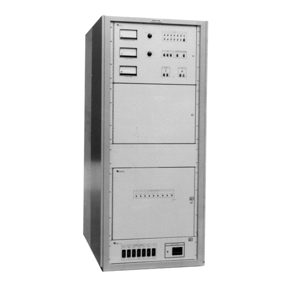
Page 25: Fm10 - 10 000 Watt Fm Broadcast Transmitter
10 000 WATT FM BROADCAST TRANSMITTER FM10 Figure 1-1 FM10 - 10 000 Watt FM Broadcast Transmitter Page 1-5 15 July 1997... - Page 26 Torque Wrench Capable of torquing to five inch-pounds Installing power MOSFETS (0.665 Newton-Meters) * - Manufactured by, or available from, Nautel Table 1-4 Glossary of Terms TERM DESCRIPTION Intermediate Power Amplifier (IPA) A module within the transmitter which amplifies the exciter's RF output to a level sufficient to drive the final RF amplifiers.
-
Page 27: Transmitter Clearances
UNPACKING AND INSTALLATION PLANNING AND SITE PREPARATION 2.1.1.3.2 Fans in the power supply draw cooling air Transmitter sites for Nautel's FM10 - through two large filters in the lower rear of the 10 000 watt FM broadcast transmitters should be... -
Page 28: Lightning Protection
50/60Hz three phase Nautel for this purpose. If used, the surge protector ac power sources. The option selected is specified by panel should be installed in close proximity to the the purchaser. -
Page 29: Power Consumption
(+) (TB1-3) and RF ON RF ON accommodate Nautel's NE50 exciter. All other (-) (TB1-4) inputs. The operation of this remote exciters must be mounted externally. The exciter's control will cause the transmitter to turn on. -
Page 30: Protection Reset
10 000 WATT FM BROADCAST TRANSMITTER FM10 2.1.7.3 Protection Reset: This remote control 2.1.8 EXCITER INTERLOCK: Protection circuit must be the equivalent of a single pole, circuitry within the transmitter will operate the momentary contact switch. The switch must be in... -
Page 31: Exciter Power Sample
10 000 WATT FM BROADCAST TRANSMITTER FM10 2.1.9.4 Exciter Power Sample: A DC voltage, 2.1.10.1 IPA/RF Fail Alarm: The IPA/RF Fail representative of the exciter forward power level, is Alarm output is applied to the IPA/RF FAIL ALARM available at the terminal (TB2- terminal TB2-1 of the control/monitor PWB (A14). -
Page 32: Ac Power Alarm
10 000 WATT FM BROADCAST TRANSMITTER FM10 2.1.10.4 AC Power Alarm: The AC Alarm output circuit) the output is an open collector. When the is applied to the terminal TB2-4 of interlock is open the output AC PWR ALARM INTLK OPEN ALARM the control/monitor PWB (A14). -
Page 33: Rf On Status
RF OFF been initiated, this output is an open collector. When Nautel. The user must supply these parts. Each the interlock circuit is intact and a local or remote installation will dictate the parts required, and will... -
Page 34: Non-Technical Pre-Commissioning
ASSEMBLY/INSTALLATION: approximately 3/8" of insulation from the end following paragraphs provide step-by-step assembly of each conductor. instructions for the FM10 transmitter, which is partially disassembled for shipment. Insert the control/monitor wiring into the NOTE terminals of the control/monitor PWB (A14)'s Partially disassembled transmitters should be TB1 and TB2, as identified in figure 2-1. -
Page 35: Installation Of Ac Power Supply Assembly
10 000 WATT FM BROADCAST TRANSMITTER FM10 NOTE Locate two black 2 AWG wires (#314 and 318) DC return for remote alarm/status monitoring that will be attached to B+ volts choke A1L1, noting circuit's DC power source should be obtained from they are tyrapped together at the right-hand side of TB2-18.DC return for the forward/reflected power... -
Page 36: Installation Of Ac Power Source Wiring
10 000 WATT FM BROADCAST TRANSMITTER FM10 NOTE Table 2-1 Power Transformer Wire Connections It is recommended a six-foot long 2 x 4 board be WIRE WIRE WIRE SOURCE used, in conjunction with the lifting bracket mounted TERM SIZE COLOUR on top of the power supply, as an aid in lifting the power supply into the transmitter. -
Page 37: Ipa/Rf Power Module Installation
10 000 WATT FM BROADCAST TRANSMITTER FM10 Table 2-2 Three-Phase AC Power Connection 2.2.7 IPA/RF POWER MODULE INSTALLATION: Install the IPA and RF power TB1-1 LINE modules as follows: TB1-2 LINE TB1-3 LINE Remove the upper, rear panel, noting there is a... - Page 38 10 000 WATT FM BROADCAST TRANSMITTER FM10 Install the six RF power modules (A18 thru Table 2-3 Module Connector Mating Information A23) in the appropriate support trays (see RF POWER CABLE DESTINATION figure MD-1). Ensure retaining studs of each MODULE module pass thru the holes in the rear of its support tray.
-
Page 39: Exciter Installation
TB1-4 (conductor) and TB1-5 (shield) specified in contract documents, this kit will be of the exciter's interface appropriate exciter installed when a Nautel exciter is to be utilized as input PWB (A10). the RF drive source. Connect the program input to the appropriate... -
Page 40: Rf Output Access
CONNECTION: Connect a continuous, low- assembly are to point upwards (refer to figure impedance conductor (0 AWG copper wire, two-inch MD-11). Tighten hardware securely. copper strap or equivalent), as described in Nautel's 'Lightning Protection for Radio Transmitter Stations' 2.2.10 INSTALLATION... -
Page 41: External Input/Output Interface
10 000 WATT FM BROADCAST TRANSMITTER FM10 Figure 2-1 External Input/Output Interface Page 2-15 01 October 2002... -
Page 42: Technical Pre-Commissioning
10 000 WATT FM BROADCAST TRANSMITTER FM10 TECHNICAL PRE-COMMISSIONING Re-install the lower panel on the rear of the Prior to applying AC power and turning on cabinet, using the attaching hardware removed the transmitter, some circuits must be customized to in step (d). -
Page 43: Primary Winding Tap Selection For Three-Phase Power Transformer A1T1
10 000 WATT FM BROADCAST TRANSMITTER FM10 Table 2-4 Primary Winding Tap Selection for Three-Phase Power Transformer A1T1 NOMINAL AC VOLTAGE PRIMARY WINDING TAPS (RMS - PHASE-TO-PHASE) 208 VOLTS 380/415 VOLTS 193 - 203 351 - 369 ø 1-A ø 2-A ø... -
Page 44: Controls And Indicators 3.1 General
10 000 WATT FM BROADCAST TRANSMITTER FM10 SECTION 3 CONTROLS AND INDICATORS GENERAL CONTROL/MONITOR FUNCTIONS CONTROLS AND INDICATORS The following section is intended to familiarize operators and maintainers with the Table lists control/monitor various controls and indicators contained in the functions controls and indicators. -
Page 45: Ac/Dc Power Supply Controls And Indicators
10 000 WATT FM BROADCAST TRANSMITTER FM10 Table 3-1 AC/DC Power Supply Controls and Indicators PANEL MARKING/ NOMENCLATURE FUNCTION USED IN TEXT Exciter Fuse MD-1 Fuses 115 VAC supply to the exciter at 5.0 amperes. A4CB1 MD-5 MAIN POWER Applies the AC power source voltage to the main power transformer when closed. - Page 46 10 000 WATT FM BROADCAST TRANSMITTER FM10 Table 3-1 AC/DC Power Supply Controls and Indicators (Continued) PANEL MARKING/ NOMENCLATURE FUNCTION USED IN TEXT MD-6 ♦ RECTIFIER A5A1DS1 When turned on, indicates temperature of rectifier assembly A2 and/or A3 is/was in excess of 90 ° C.
- Page 47 10 000 WATT FM BROADCAST TRANSMITTER FM10 Table 3-1 AC/DC Power Supply Controls and Indicators (Continued) PANEL MARKING/ NOMENCLATURE FUNCTION USED IN TEXT MD-6 ♦ PA VDC FAIL A5A1DS4 When turned on indicates one of the following: PWR SPLY B Output of the 'B' PA switching power supply is/was in excess of 55 VDC.
- Page 48 10 000 WATT FM BROADCAST TRANSMITTER FM10 Table 3-1 AC/DC Power Supply Controls and Indicators (Continued) PANEL MARKING/ NOMENCLATURE FUNCTION USED IN TEXT MD-6 ♦ A5A1DS6 PA VDC FAIL When turned on indicates one of the following: PWR SPLY D Output of the 'D' PA switching power supply is/was in excess of 55 VDC.
- Page 49 10 000 WATT FM BROADCAST TRANSMITTER FM10 Table 3-1 AC/DC Power Supply Controls and Indicators (Continued) PANEL MARKING/ NOMENCLATURE FUNCTION USED IN TEXT MD-6 ♦ PA VDC FAIL A5A1DS8 When turned on indicates one of the following: PWR SPLY F Output of the 'F' PA switching power supply is/was in excess of 55 VDC.
- Page 50 10 000 WATT FM BROADCAST TRANSMITTER FM10 Table 3-1 AC/DC Power Supply Controls and Indicators (Continued) PANEL MARKING/ NOMENCLATURE FUNCTION USED IN TEXT MD-2 ♥ A6A2F1 PA VDC (A) Fuses regulated DC supply voltage being applied to power amplifiers ½ in module A at 25 amperes.
- Page 51 10 000 WATT FM BROADCAST TRANSMITTER FM10 Table 3-1 AC/DC Power Supply Controls and Indicators (Continued) PANEL MARKING/ NOMENCLATURE FUNCTION USED IN TEXT MD-2 ♥ A9A2F3 PA VDC (D) Fuses regulated DC supply voltage being applied to power amplifiers 5/6 in module D at 25 amperes.
- Page 52 10 000 WATT FM BROADCAST TRANSMITTER FM10 Table 3-1 AC/DC Power Supply Controls and Indicators (Continued) PANEL MARKING/ NOMENCLATURE FUNCTION USED IN TEXT A26A1F2 MD-13 24 VDC (IPA FANS) Fuses unregulated 24 VDC being applied to the cooling air fan in the IPA module at 2.0 amperes.
- Page 53 10 000 WATT FM BROADCAST TRANSMITTER FM10 Table 3-1 AC/DC Power Supply Controls and Indicators (Continued) PANEL MARKING/ NOMENCLATURE FUNCTION USED IN TEXT A26TP3 MD-12 -15 VDC Provides a convenient measurement point for the – supply. A26TP4 MD-12 +5 VDC Provides a convenient measurement point for the +5 VDC supply.
-
Page 54: Control/Monitor Function Controls And Indicators
10 000 WATT FM BROADCAST TRANSMITTER FM10 Table 3-2 Control/Monitor Function Controls and Indicators PANEL MARKING/ NOMENCLATURE FUNCTION USED IN TEXT A13A1DS1 MD-7 PA FAIL ALARM When turned on, indicates failure of one or more MD-8 amplifiers within an RF power amplifier module. - Page 55 10 000 WATT FM BROADCAST TRANSMITTER FM10 Table 3-2 Control/Monitor Function Controls and Indicators (Continued) PANEL MARKING/ NOMENCLATURE FUNCTION USED IN TEXT A13A1DS9 MD-7 REFLD PWR ALARM When turned on, indicates a reflected power in excess MD-8 of 100 watts is/was being reflected back to the output of the RF power amplifier modules.
- Page 56 10 000 WATT FM BROADCAST TRANSMITTER FM10 Table 3-2 Control/Monitor Function Controls and Indicators (Continued) PANEL MARKING/ NOMENCLATURE FUNCTION USED IN TEXT A13A1DS15 MD-7 RF ON When turned on, indicates the control/monitor PWB's MD-8 on/off circuitry is set to its 'RF on' state and the RF power stages are enabled.
- Page 57 10 000 WATT FM BROADCAST TRANSMITTER FM10 Table 3-2 Control/Monitor Function Controls and Indicators (Continued) PANEL MARKING/ NOMENCLATURE FUNCTION USED IN TEXT A13A1S8 MD-7 TRANSMITTER OUTPUT Increases RF output power level each time switch is POWER RAISE MD-8 pressed and released. RF power is increased from zero watts to 11 000 watts in 256 steps.
- Page 58 10 000 WATT FM BROADCAST TRANSMITTER FM10 Table 3-2 Control/Monitor Function Controls and Indicators (Continued) PANEL MARKING/ NOMENCLATURE FUNCTION USED IN TEXT MD-2 ♠ A14BT2 BATTERY Contributes 1.5 VDC towards a 4.5 VDC power source that is utilized as an uninterruptible power supply.
- Page 59 10 000 WATT FM BROADCAST TRANSMITTER FM10 Table 3-2 Control/Monitor Function Controls and Indicators (Continued) PANEL MARKING/ NOMENCLATURE FUNCTION USED IN TEXT MD-2 ♠ A14R138 IPA HIGH THR Adjusted to set the IPA forward power monitor threshold to 600 watts.
-
Page 60: Rf Power Stage Controls And Indicators
10 000 WATT FM BROADCAST TRANSMITTER FM10 Table 3-3 RF Power Stage Controls and Indicators PANEL MARKING/ NOMENCLATURE FUNCTION USED IN TEXT A16A1C2 MD-10 RATIO Adj Adjusted to optimize directivity of the IPA Input Power Probe A16 at the desired operating frequency. -
Page 61: Rf Power Module Control And Indicators
10 000 WATT FM BROADCAST TRANSMITTER FM10 Table 3-4 RF Power Module Control and Indicators PANEL MARKING/ NOMENCLATURE FUNCTION USED IN TEXT ♦ C3 OUTPUT TUNE Adjusted to series resonate the leakage inductance of transformer T1's secondary winding at a frequency which optimizes the amplifier's power gain. - Page 62 10 000 WATT FM BROADCAST TRANSMITTER FM10 Table 3-4 RF Power Module Control and Indicators (Continued) PANEL MARKING/ NOMENCLATURE FUNCTION USED IN TEXT NOTES Partial reference designations are listed. Prefix with A18, A19, A20, A21, A22 or A23 for full reference designations.
-
Page 63: Ipa Module Controls And Indicators
10 000 WATT FM BROADCAST TRANSMITTER FM10 Table 3-5 IPA Module Controls and Indicators PANEL MARKING/ NOMENCLATURE FUNCTION USED IN TEXT A17 ♦ C3 Adjusted to series resonate the leakage inductance of OUTPUT TUNE transformer T1's secondary winding at a frequency which optimizes the amplified power gain. -
Page 64: Commissioning/Operation Instructions
10 000 WATT FM BROADCAST TRANSMITTER FM10 SECTION 4 COMMISSIONING/OPERATION INSTRUCTIONS GENERAL If the front of the transmitter is accessible, The following instructions are primarily press and release the control/monitor panel's intended for persons involved in the commissioning, switch (local or remote control). -
Page 65: Turning On The Transmitter
10 000 WATT FM BROADCAST TRANSMITTER FM10 TURNING ON THE TRANSMITTER 4.7.1 The total DC current being drawn by the Turn on the transmitter as described in transmitter must not exceed the level specified as paragraph 4.10 for initial startup and after repairs... -
Page 66: Commissioning Procedures
10 000 WATT FM BROADCAST TRANSMITTER FM10 COMMISSIONING PROCEDURES NOTE 4.10 commissioning procedures The control/monitor PWB (A14) is located at the presented in a step-by-step format to permit a person inside, top, left of the cabinet. Refer to figure MD-2... -
Page 67: Preliminary Settings
10 000 WATT FM BROADCAST TRANSMITTER FM10 Using IPA input power probe's output cable NOTE (W40), connect the exciter's RF output to the The data in table 5-6 was compiled at the factory IPA module's RF input connector (A17J5). with the transmitter terminated in a precision 50- ohm dummy load. -
Page 68: Enabling Of Rf Power Circuits
10 000 WATT FM BROADCAST TRANSMITTER FM10 meter indication meter indication DC SUPPLY VOLTAGE DC SUPPLY CURRENT should be between 14.0 and 16.0 volts DC. should be near zero amperes. Set the switch to Set the switch to DC SUPPLY VOLTAGE... -
Page 69: Putting Transmitter In Service
10 000 WATT FM BROADCAST TRANSMITTER FM10 Simultaneously monitor the Continue to press the SUPPLY OUTPUT POWER - RAISE switch for a meter VOLTAGE , SUPPLY CURRENT DC SUPPLY VOLTAGE meter indication of the PA voltage recorded as PA FORWARD/REFLECTED... -
Page 70: System Level Trouble Shooting
(if one is available). It is recommended The FM10 transmitter contains many solid state that the significance of remote indications and the devices that may be damaged if subjected to appropriate responses be incorporated into a station's excessive heat or high voltage transients. -
Page 71: Local Trouble Shooting
10 000 WATT FM BROADCAST TRANSMITTER FM10 5.3.1.2 Local Trouble Shooting: Local on-air 5.3.2.1 When the intermediate power amplifier trouble shooting consists monitoring (IPA) module is defective and a serviceable transmitter's integral meters and fault alarm replacement is not available, it can be replaced by an indicators. -
Page 72: Stress Current Protection
10 000 WATT FM BROADCAST TRANSMITTER FM10 Table 5-1 PA Failures Versus RF Output DISABLED POWER AMPLIFIERS POWER REDUCTION NOMINAL AND/OR RELATIVE TO RF CARRIER RF POWER MODULES 10 000 WATTS OUTPUT One Power Amplifier -0.25dB 9450 Watts Two Power Amplifiers -0.50dB... -
Page 73: Fuse Versus Power Amplifier Fet
10 000 WATT FM BROADCAST TRANSMITTER FM10 Table 5-2 Fuse Versus Power Amplifier FET If the meter reading in step (a) is the normal operating level, the alarm is probably false. FUSE POWER Press/release the switch. ALARM RESET MODULE If the meter reading in step (a) is below the... - Page 74 10 000 WATT FM BROADCAST TRANSMITTER FM10 NOTE If a pair of adjacent RF power module lamps is on (ie. Q1/Q2, Q3/Q4, If the voltage measured in step (j) is not the nominal ALARM Q5/Q6), it is probable that a fuse has blown in PA supply volts level, it is probable that the the associated switching power supply.
-
Page 75: Replacement Of Rf Power Module
10 000 WATT FM BROADCAST TRANSMITTER FM10 Disconnect suspect PA's PA output cable (W1 5.7.1 RF POWER MODULE REMOVAL: thru W36) from the combiner end (see table 9- Remove a defective RF power module as follows: 7) and connect it through an in-line power meter to a 50 ohm, 500W load. -
Page 76: Rf Power Amplifier Tuning
10 000 WATT FM BROADCAST TRANSMITTER FM10 Table 5-3 Power Module Mating Connectors MATING CONNECTORS FOR MODULE CONNECTOR MODULE MODULE MODULE MODULE MODULE MODULE W1P1 W7P1 W13P1 W19P1 W25P1 W31P1 W2P1 W8P1 W14P1 W20P1 W26P1 W32P1 W3P1 W9P1 W15P1 W21P1... -
Page 77: Test Equipment For Tuning
Tuning shelf, complete with attached tuning dummy load, and attenuator. One to interconnect output of tuning shelf's B+ extender cable - Nautel part number 182- tuning attenuator and the input of the RF power 5020. probe connected to RF power module interface PWB's PA TUNE BNC connector. -
Page 78: Test Interconnection For Rf Power Module To Be Tuned
10 000 WATT FM BROADCAST TRANSMITTER FM10 Figure 5-1 Test Interconnection for RF Power Module to be Tuned Page 5-9 01 October 2002... -
Page 79: Tuning Procedure
10 000 WATT FM BROADCAST TRANSMITTER FM10 Table 5-4 Component Association for Tuning COMPONENT POWER AMPLIFIER CHANNEL INPUT PA A2 OUTPUT PA TUNE SWITCH A13S2-1 A13S1-2 A13S1-1 A13S2-2 A13S3-1 A13S3-2 RF OUTPUT P2 of cable assembly 161-5017 mates with the... - Page 80 PA input PWB. In this case, L1 may be replaced by a slightly larger inductance coil (Nautel Part # Turn on RF power module selected as tuning 161-1019-05), located in the ancillary kit.
-
Page 81: Completion Of Tuning
10 000 WATT FM BROADCAST TRANSMITTER FM10 switch for the power Ensure the top panel at the rear of the TUNE/NORMAL amplifier channel that was being tuned to transmitter cabinet (refer to figure MD-2) has been removed. NORMAL Repeat steps (f) thru (s) for each power Secure the RF power module to its support amplifier channel to be tuned. -
Page 82: Rf Power Module Removal
10 000 WATT FM BROADCAST TRANSMITTER FM10 TEMPORARY REPLACEMENT MODULE WITH RF POWER MODULE The transmitter can operate, at a reduced When disconnecting cable mating connectors from power level, with the IPA module replaced by an J1 thru J6 or J9 on the rear of the RF power operational RF power module. -
Page 83: Control/Monitor Pwb Replacement/Adjustment
10 000 WATT FM BROADCAST TRANSMITTER FM10 FLOATING FLOATING RF POWER MODULE CONNECTOR CONNECTOR CONNECTOR CONNECTOR W37P1 W38P1 W37P1 W38P1 W40P2 Locate the IPA Input Matching Assembly (182- Remove attaching hardware (hexagon nuts and 5015-**) provided with the ancillary kit. - Page 84 10 000 WATT FM BROADCAST TRANSMITTER FM10 Disconnect the remote control and status wiring Remove external power supply from P27-1 and connected to TB1 and TB2. Disconnect all reconnect wire disconnected in step (g). mating plugs to the control/monitor PWB and carefully remove all mounting hardware.
- Page 85 10 000 WATT FM BROADCAST TRANSMITTER FM10 POWER SUPPLY CONTROL Turn on the and all MAIN POWER PWR MDL REPLACEMENT thru circuit breakers. 5.10 Install a replacement power supply control Simultaneously press control/monitor PWB as follows: panel's OUTPUT POWER - RAISE...
-
Page 86: Fault Analysis - No Rf Output Or Reduced Rf Output
10 000 WATT FM BROADCAST TRANSMITTER FM10 Table 5-5 Fault Analysis - No RF Output or Reduced RF Output ALARM LAMP STATUS PROBABLE CAUSE RF off selected. To restore normal operation, select RF ON INTERLOCK OPEN RF ON off and To restore normal operation, close the external interlock switches. - Page 87 10 000 WATT FM BROADCAST TRANSMITTER FM10 Table 5-5 Fault Analysis - No RF Output or Reduced RF Output ALARM LAMP STATUS PROBABLE CAUSE The reflected power detected by the transmitters output power probe REFLD PWR has exceeded 100 watts and, if above 440 watts, the transmitter's output power has been reduced by the protection circuitry to prevent damage to the RF power amplifiers.
-
Page 88: Pa Fail Alarm
10 000 WATT FM BROADCAST TRANSMITTER FM10 TROUBLE SHOOTING FRONT PANEL If the control/monitor panel's lamp is PA FAIL ALARMS on or any RF power module PA alarm lamps 5.11 The trouble shooting of front panel alarms (Q1 thru Q6) are on, but no reduction in RF... -
Page 89: Module Temp Alarm
10 000 WATT FM BROADCAST TRANSMITTER FM10 NOTE NOTE Following each trouble shooting action taken on the If it is necessary to check the control/monitorPWB's alarm, press intermediate RF level monitor circuitry, refer to the MODULE RF DRIVE MODULE RESET switches. -
Page 90: Ac Phase Alarm
10 000 WATT FM BROADCAST TRANSMITTER FM10 Check for air flow out of the front of the NOTE module and perform a visual inspection for fan Random alarm occurrences can result from blockage. If a blockage exists, it will be... -
Page 91: Low Ac Pwr Alarm
10 000 WATT FM BROADCAST TRANSMITTER FM10 NOTE Measure the voltage between J2-12 (+) of the Random alarm occurrences can result from AC line low voltage power supply PWB (A26A1), voltage fluctuations at the service entrance. representative of the AC line voltage, and Monitor the AC line voltage and contact the power ground (-). -
Page 92: Reflected Power Zero Watts And Forward Power Normal
10 000 WATT FM BROADCAST TRANSMITTER FM10 At least four transient SWR conditions, in If the external reflected power meter's reading excess of 2:1 (1220 watts), were detected is near zero watts, a problem may exist with the within a five second time interval indicating... -
Page 93: Ipa Input Alarm
10 000 WATT FM BROADCAST TRANSMITTER FM10 If no cause for the mismatch can be located in 5.11.8.3 RF Drive Checks: the antenna system or RF feed cable, suspect a problem with the control/monitor PWB's Read the exciter's forward power meter. If the reflected power detection circuitry. -
Page 94: Ipa Output Alarm
10 000 WATT FM BROADCAST TRANSMITTER FM10 5.11.8.3.3High RF Drive: The exciter power has 5.11.9.3 Control/Monitor PWB IPA Output probably exceeded the high RF drive threshold Monitor Check: Determine whether (nominally 33 watts). Decrease the exciter output control/monitor PWB's IPA Output circuit is... -
Page 95: Ipa Forward Power
10 000 WATT FM BROADCAST TRANSMITTER FM10 NOTE NOTE If one of the six-way splitter's cables has open or Following each trouble shooting action taken on the short circuited, the associated RF power module's alarm, press the switch. If IPA TEMP... -
Page 96: Low Supply Output
10 000 WATT FM BROADCAST TRANSMITTER FM10 NOTE If the switching power supply module's output If it is necessary to check the control/monitor PWB's voltage is normal, a possible fault exists in the IPA module temperature circuitry, refer to the... -
Page 97: Pwr Sply Fail Ipa Alarm
10 000 WATT FM BROADCAST TRANSMITTER FM10 Since the circuit breaker could not be reset, it is Allow the system to run to see if the alarm probable that the alarm was triggered due to an reoccurs. If the alarm reoccurs, refer to the... -
Page 98: Rectifier Temperature Alarm
NOTE Two types of air cooling are available for use with the FM10. In an open air system, the transmitter WARNING will contain four air filters, located in the rear (Nautel part number - HR51). -
Page 99: Tuning Shelf Installation
10 000 WATT FM BROADCAST TRANSMITTER FM10 Figure 5-2 Tuning Shelf Installation Page 5-30 01 October 2002... -
Page 100: Factory Determined Measurements For Critical Parameters
10 000 WATT FM BROADCAST TRANSMITTER FM10 Table 5- Factory Determined Measurements for Critical Parameters SER # _________ CARRIER FREQ ( ƒ c) __________MHz ASSIGNED FWD PWR __________WATTS RF DRIVE RELATED MEASUREMENTS IPA MODULE INPUT (A17J5) __________W RF DRIVE LEVEL (A14TP7) - Page 101 10 000 WATT FM BROADCAST TRANSMITTER FM10 Table 5-6 Factory Determined Measurements for Critical Parameters (Continued) PROTECTION CIRCUIT RELATED MEASUREMENTS AT ASSIGNED POWER LEVEL (Default = 10kW) LOW INTERMEDIATE RF (A14U36-8) __________ VDC IPA VOLTS CONTROL (A14TP4) __________ VDC PA VOLTS CONTROL (A14TP2)
-
Page 102: Theory Of Operation
10 000 WATT FM BROADCAST TRANSMITTER FM10 SECTION 6 THEORY OF OPERATION GENERAL 6.3.1.1.1 The 3-phase 'X' and 'Y' secondary The theory of operation for the subject windings are the voltage source (54.9 VAC phase-to- transmitter is presented in this section. -
Page 103: Circuit Breaker Panel
10 000 WATT FM BROADCAST TRANSMITTER FM10 6.3.3 CIRCUIT BREAKER PANEL: 6.3.4.1.2 +24V Fan Supply: FET source followers figure SD-3. The circuit breaker panel (A4) is the Q3, Q4 and their associated components comprise a transmitter's B+ volts reservoir distribution point. -
Page 104: 3-Phase Monitor Pwb
(turned on) and relay K1 will be phase loss occurs. The FM10 transmitter only energized. The AC alarm output at J2-1 will be an utilizes the alarm status applied between J2-5/J2-6 by... -
Page 105: Power Supply Control Pwb (A5A1)
10 000 WATT FM BROADCAST TRANSMITTER FM10 purposes. Output level and voltage regulation is 6.3.7.2 IPA Volts Control: The IPA Volts controlled by switching FETs on the power supplies. Control signal (J3-1/2), provided by the control/ FET gate drive is supplied by the power supply... -
Page 106: Pa Volts Monitor
10 000 WATT FM BROADCAST TRANSMITTER FM10 de-energized. When the reservoir capacitor has 6.3.7.5 IPA Volts Monitor: The IPA Volts charged sufficiently so that the voltage at the (-) input Sample output from IPA switching power supply is has dropped to a nominal 5 VDC, a low (near 0.0... -
Page 107: 3-Phase Rectifier Assemblies
10 000 WATT FM BROADCAST TRANSMITTER FM10 RF POWER STAGE 6.3.7.6.2 3 Phase Rectifier Assemblies: Each 3- phase rectifier assembly (A2 and A3) contains a See figures SD-6 and SD-7. The RF thermistor whose output is applied to the Rectifier power stage generates the final RF output. -
Page 108: Ipa Output Splitter
10 000 WATT FM BROADCAST TRANSMITTER FM10 6.4.3.2 IPA Output Splitter: The IPA output control/monitor PWB to sense excessive module splitter section provides six equal, phase coherent temperature and power amplifier failures. Refer to signals to drive the RF power modules. It is a six... -
Page 109: Control/Monitor Function
10 000 WATT FM BROADCAST TRANSMITTER FM10 CONTROL/MONITOR FUNCTION 6.5.2 CONTROL/MONITOR PWB: See figure SD-9. The control/monitor figure SD-9. The control/monitor PWB (A14) functions provides local transmitter controls and determines and regulates the RF output of the analog meters to display transmitter RF power and transmitter, monitors the critical parameters of the critical DC voltage/current levels. -
Page 110: Local/Remote Control Selection
10 000 WATT FM BROADCAST TRANSMITTER FM10 indications for remote metering, is disabled (open circuit), J6-6 will switch to ground B+ VOLTS SAMPLE (TB1-16) and (TB1-17) which (RF On) causing the low voltage power supply to TOTAL CUR SAMPLE provide final amplifier DC voltage and current level remove the 24 VDC supply from the cooling fans and indications for remote metering. -
Page 111: Automatic Level Control (Alc)
10 000 WATT FM BROADCAST TRANSMITTER FM10 time the switch (A13A1S9) is switch (A13A1S7) or by applying a remote POWER LOWER momentarily pressed, a ground is applied to the Pwr command (TB1-5/6). PROTECTION RESET Decrease input (J2-41) and is detected by the counter circuit. -
Page 112: Pa Fail Alarm
10 000 WATT FM BROADCAST TRANSMITTER FM10 greater than 2.3 VDC. When the RF drive to an RF threshold, the PA Volts Control output will be power module drops below the acceptable threshold, inhibited (0.0 VDC). This will inhibit the output of... -
Page 113: Transmitter Reflected Power
10 000 WATT FM BROADCAST TRANSMITTER FM10 6.5.2.21 Transmitter Reflected Power: 6.5.2.22 High AC Power: See figures SD-9 and figures SD-9 and SD-10. The Refld Pwr input (J6-2) SD-10. The +24V (Unreg) input (J1-12) is the is a DC voltage that is proportional to the amount of... -
Page 114: Component Level Trouble Shooting
10 000 WATT FM BROADCAST TRANSMITTER FM10 SECTION 7 COMPONENT LEVEL TROUBLE SHOOTING TROUBLE SHOOTING REFERENCE DATA necessary, refer figure SD-4 of this manual for a The information provided in this section is schematic diagram and to section 6 of this manual for intended to assist an experienced electronic technician detailed circuit description. -
Page 115: Fet Gate Drive
10 000 WATT FM BROADCAST TRANSMITTER FM10 Table 7-1 Test Voltages/Waveforms - Switching Power Supply LOCATION DESCRIPTION TEST VOLTAGE/WAVEFORM B+ Volts 72 VDC PA Volts 48.7 VDC P1-3 FET Gate Drive See Figure 7-1 P2-2 PA Volts Sample See Figure 7-2... -
Page 116: Test Voltages/Waveforms - Power Supply Control Pwb
10 000 WATT FM BROADCAST TRANSMITTER FM10 Table 7-2 Test Voltages/Waveforms - Power Supply Control PWB LOCATION DESCRIPTION TEST VOLTAGE/WAVEFORM CR15/16/17/18/19/20-Cathode FET Gate Drive See Figure 7-1 CR21-Cathode See Figure 7-10 CR30/31/32/33/137/138-Anode See Figure 7-11 CR34-Anode 2.3 VDC CR47-Anode 2.3 VDC CR48-Anode 2.3 VDC... -
Page 117: Test Voltages - Low Voltage Power Supply Pwb
10 000 WATT FM BROADCAST TRANSMITTER FM10 Table 7-2 Test Voltages/Waveforms - Power Supply Control PWB (Continued) LOCATION DESCRIPTION TEST VOLTAGE/WAVEFORM >3.6 - 4.2 VDC @ T (Ambient) = 25 ° C TP36 - >3.6 - 4.2 VDC @ T (Ambient) = 25 ° C... -
Page 118: 100Khz Oscillator Waveform
10 000 WATT FM BROADCAST TRANSMITTER FM10 2.0 µs/div, 1.0 V/div, 0.0 VDC indicated as Gnd 5.0 µs/div, 1.0 V/div, Scale Centre = 0.0 VDC Figure 7-4 100kHz Oscillator Waveform Figure 7-6 50kHz Ramp Waveform 5.0 µs/div, 1.0 V/div, 0.0 VDC indicated as Gnd 5.0 µs/div, 5.0 V/div, 0.0 VDC indicated as Gnd... -
Page 119: Tp18 Waveform
10 000 WATT FM BROADCAST TRANSMITTER FM10 5.0 µs/div, 5.0 V/div, 0.0 VDC indicated as Gnd 5.0 µs/div, 20.0 V/div, 0.0 VDC indicated as Gnd Figure 7-8 TP18 Waveform Figure 7-10 CR21-Cathode Waveform 5.0 µs/div, 5.0 V/div, 0.0 VDC indicated as Gnd 5.0 ms/div, 0.5 V/div, 0.0 VDC indicated as Gnd... -
Page 120: Test Voltages - Control/Monitor Pwb
10 000 WATT FM BROADCAST TRANSMITTER FM10 Table 7-5 Test Voltages - Control/Monitor PWB LOCATION DESCRIPTION TEST VOLTAGE 8.5 - 11.5 VDC @ T (Ambient) = 25 ° C J1-2 Temp (IPA) Ref 8.5 - 11.5 VDC @ T (Ambient) = 25 ° C... -
Page 121: Parts List
CONTROL NUMBER IS KNOWN: Locate the column in the reference designation indexes. information for a part when the Nautel configuration control number is known, as follows: 8.6.1 USE CODE COLUMN: This column... -
Page 122: Ref Des Column
The use of this number does not restrict Nautel from SMT - Denotes item is designed to be installed selecting and using commercial equivalents, where using Surface Mount Technology. -
Page 123: Manufacturers' Code To Address Index
10 000 WATT FM BROADCAST TRANSMITTER FM10 Table 8-1 Manufacturers' Code to Address Index 24602 EMC Technology Incorporated, 0GZ58 Huber and Suhner Incorporated, 1971 Old Cuthbet Road, 1 Allen Martin Drive, Cherry Hill, New Jersey 08034 P O Box 400,... - Page 124 Hepco/Electra Inc., 6071 St. Andrews Rd., 80294 Bourns Incorporated, Columbia, South Carolina 29210 Instrument Division, 6135 Magnolia Avenue, 57655 Nautel Maine Incorporated, Riverside, California 92506 201 Target Industrial Circle Bangor, Maine 04401 81483 International Rectifier, 9220 Sunset Boulevard, 59124 KOA Speer Electronics Incorporated,...
- Page 125 10 000 WATT FM BROADCAST TRANSMITTER FM10 This Page Intentionally Left Blank Page 8-5 15 November 1999...
-
Page 126: Family Tree - Fm10 10Kw Fm Broadcast Transmitter
10 000 WATT FM BROADCAST TRANSMITTER FM10 Figure 8-1 Family Tree - FM10 10kW FM Broadcast Transmitter (Sheet 1 of 2) Page 8-6 15 November 1999... - Page 127 10 000 WATT FM BROADCAST TRANSMITTER FM10 Figure 8-1 Family Tree - FM10 10kW FM Broadcast Transmitter (Sheet 2 of 2) Page 8-7 15 November 1999...
-
Page 128: Ref Des Index - Fm10 10Kw Fm Broadcast Transmitter
10 000 WATT FM BROADCAST TRANSMITTER FM10 Table 8-2 Ref Des Index - FM10 10kW FM Broadcast Transmitter NAME OF PART NAUTEL'S JAN/MIL/OEM CODE AND DESCRIPTION PART NO. PART NO. CODE Transmitter, FM, 10kW, Open Cooling FM10 182-8300-02 37338 Power Supply, AC/DC, 208 VAC 50/60Hz, 3ø... - Page 129 10 000 WATT FM BROADCAST TRANSMITTER FM10 Table 8-2 Ref Des Index - FM10 10kW FM Broadcast Transmitter (Continued) NAME OF PART NAUTEL'S JAN/MIL/OEM CODE AND DESCRIPTION PART NO. PART NO. CODE RF Power Module NAA41 See NAA41 Manual 37338...
- Page 130 10 000 WATT FM BROADCAST TRANSMITTER FM10 Table 8- Ref D- Index - FM10 10kW FM Broadcast Transmitter (Continued) NAME OF PART NAUTEL'S JAN/MIL/OEM CODE AND DESCRIPTION PART NO. PART NO. CODE Connector, Size 17-16, 10 Socket-Contacts 182-5013 182-5013 37338...
- Page 131 10 000 WATT FM BROADCAST TRANSMITTER FM10 Table 8-2 Ref Des Index - FM10 10kW FM Broadcast Transmitter (Continued) NAME OF PART NAUTEL'S JAN/MIL/OEM CODE AND DESCRIPTION PART NO. PART NO. CODE ƒ Coaxial Cable, RF(Specify ƒ c), Non-Reparable 182-8050-W15...
- Page 132 10 000 WATT FM BROADCAST TRANSMITTER FM10 Table 8-2 Ref Des Index - FM10 10kW FM Broadcast Transmitter (Continued) NAME OF PART NAUTEL'S JAN/MIL/OEM CODE AND DESCRIPTION PART NO. PART NO. CODE NOTE: Duplicated reference designations indicate an option exists for that item. Refer to description and/or the use code to determine which item/variation is required for a specific installation.
-
Page 133: Ref Des Index - Nasr92 Ac/Dc Power Supply
10 000 WATT FM BROADCAST TRANSMITTER FM10 Table 8-3 Ref Des Index - NASR92 AC/DC Power Supply NAME OF PART NAUTEL'S JAN/MIL/OEM CODE AND DESCRIPTION PART NO. PART NO. CODE Power Supply, AC/DC, 208 VAC, 50/60Hz, 3ø NASR92/02 182-7200-02 37338 Power Supply, AC/DC, 208 VAC, 50/60Hz, 3ø... -
Page 134: Ref Des Index - Nag02 Circuit Breaker Panel
10 000 WATT FM BROADCAST TRANSMITTER FM10 Table 8-4 Ref Des Index - NAG02 Circuit Breaker Panel NAME OF PART NAUTEL'S JAN/MIL/OEM CODE AND DESCRIPTION PART NO. PART NO. CODE Circuit Breaker Panel, 208 VAC, 50/60Hz, 3ø NAG02/01 182-7215-01 37338 Circuit Breaker Panel, 380-415 VAC, 50/60Hz, 3ø... -
Page 135: Ref Des Index - Nac66 Control/Monitor Panel
10 000 WATT FM BROADCAST TRANSMITTER FM10 Table 8-5 Ref Des Index - NAC66 Control/Monitor Panel NAME OF PART NAUTEL'S JAN/MIL/OEM CODE AND DESCRIPTION PART NO. PART NO. CODE Control/Monitor Panel NAC66/01A 182-4000-03 37338 Control/Monitor Panel NAC66/03 182-4000-04 37338 Control/Display PWB... -
Page 136: Ref Des Index - Napd05/01A Control/Display Pwb
10 000 WATT FM BROADCAST TRANSMITTER FM10 Table 8-6 Ref Des Index - NAPD05/01A Control/Display PWB NAME OF PART NAUTEL'S JAN/MIL/OEM CODE AND DESCRIPTION PART NO. PART NO. GRID CODE Control/Display PWB NAPD05/01A 182-4044-02 37338 Diode, General Purpose, 200V, 0.1A... - Page 137 10 000 WATT FM BROADCAST TRANSMITTER FM10 Table 8-6 Ref Des Index - NAPD05/01A Control/Display PWB (Continued) NAME OF PART NAUTEL'S JAN/MIL/OEM CODE AND DESCRIPTION PART NO. PART NO. GRID CODE Header, MTA, 12 Square Posts, 0.156 Centre JU21 1-640383-2 09482 Header, MTA, 4 Square Posts, 0.156 Centre...
- Page 138 10 000 WATT FM BROADCAST TRANSMITTER FM10 Table 8-6 Ref Des Index - NAPD05/01A Control/Display PWB (Continued) NAME OF PART NAUTEL'S JAN/MIL/OEM CODE AND DESCRIPTION PART NO. PART NO. GRID CODE Switch, Pushbutton, Momentary, PWB Mount SCP11 MP01-R0-2-C2-B-E 09353 Switch, Pushbutton, Momentary, PWB Mount...
-
Page 139: Ref Des Index - Nai07 Intermediate Rf Drive Splitter
10 000 WATT FM BROADCAST TRANSMITTER FM10 Table 8-7 Ref Des Index - NAI07 Intermediate RF Drive Splitter NAME OF PART NAUTEL'S JAN/MIL/OEM CODE AND DESCRIPTION PART NO. PART NO. CODE Intermediate RF Drive Splitter NAI07 182-8039 37338 Intermediate RFDrive Splitter... - Page 140 10 000 WATT FM BROADCAST TRANSMITTER FM10 Table 8-8 Ref Des Index - NAFP68 IPA Input RF Power Probe NAME OF PART NAUTEL'S JAN/MIL/OEM CODE DES AND DESCRIPTION PART NO. PART NO. CODE IPA Input RF Power Probe NAFP68 182-8019...
-
Page 141: Ref Des Index - Naf79 10Kw Rf Combiner/Filter
10 000 WATT FM BROADCAST TRANSMITTER FM10 Table 8-9 Ref Des Index - NAF79 10kW RF Combiner/Filter NAME OF PART NAUTEL'S JAN/MIL/OEM CODE AND DESCRIPTION PART NO. PART NO. CODE RF Combiner/Filter, 10kW NAF79 182-6000 37338 RF Combiner/Filter, 10kW NAF79A... -
Page 142: Ref Des Index - Nafp64 10Kw Rf Power Probe
10 000 WATT FM BROADCAST TRANSMITTER FM10 Table 8-10 Ref Des Index - NAFP64 10kW RF Power Probe NAME OF PART NAUTEL'S JAN/MIL/OEM CODE AND DESCRIPTION PART NO. PART NO. CODE RF Power Probe, 10kW NAFP64 182-6005 37338 Forward Power Probe PWB... -
Page 143: Ref Des Index - Nas43/02 Low Voltage Power Supply
10 000 WATT FM BROADCAST TRANSMITTER FM10 Table 8-11 Ref Des Index - NAS43/02 Low Voltage Power Supply NAME OF PART NAUTEL'S JAN/MIL/OEM CODE AND DESCRIPTION PART NO. PART NO. CODE Low Voltage Power Supply NAS43/02 182-7040-02 37338 Low Voltage Power Supply... -
Page 144: Ref Des Index - Naps09C/01 Low Voltage Power Supply Pwb
10 000 WATT FM BROADCAST TRANSMITTER FM10 Table 8-12 Ref Des Index - NAPS09C/01 Low Voltage Power Supply PWB NAME OF PART NAUTEL'S JAN/MIL/OEM CODE AND DESCRIPTION PART NO. PART NO. GRID CODE Low Voltage Power Supply PWB NAPS09C/01 182-7045-05... - Page 145 10 000 WATT FM BROADCAST TRANSMITTER FM10 Table 8-12 Ref Des Index - NAPS09C/01 Low Voltage Power Supply PWB (Continued) NAME OF PART NAUTEL'S JAN/MIL/OEM CODE AND DESCRIPTION PART NO. PART NO. GRID CODE Fuse, 2A, 250V, Slow, 3AG FA11...
- Page 146 10 000 WATT FM BROADCAST TRANSMITTER FM10 Table 8-12 Ref Des Index - NAPS09C/01 Low Voltage Power Supply PWB (Continued) NAME OF PART NAUTEL'S JAN/MIL/OEM CODE AND DESCRIPTION PART NO. PART NO. GRID CODE NOTE: Duplicated reference designations indicate an option exists for that item. Refer to description and/or the use code to determine which item/variation is required for a specific installation.
-
Page 147: Ref Des Index - Napc60/03 3-Phase Monitor Pwb
10 000 WATT FM BROADCAST TRANSMITTER FM10 Table 8-13 Ref Des Index - NAPC60/03 3-Phase Monitor PWB NAME OF PART NAUTEL'S JAN/MIL/OEM CODE AND DESCRIPTION PART NO. PART NO. GRID CODE 3-Phase Monitor PWB NAPC60/03 166-7026-03 37338 Capacitor, Tantalum, 6.8uF 10% 35V... - Page 148 10 000 WATT FM BROADCAST TRANSMITTER FM10 Table 8-13 Ref Des Index - NAPC60/03 3-Phase Monitor PWB (Continued) NAME OF PART NAUTEL'S JAN/MIL/OEM CODE AND DESCRIPTION PART NO. PART NO. GRID CODE IC, Operational Amplifier, Dual UD02 LM258J 04713 Socket, Relay...
-
Page 149: Wiring List
10 000 WATT FM BROADCAST TRANSMITTER FM10 SECTION WIRING LISTS INTRODUCTION PRINTED WIRING PATTERNS This section contains wiring information for The need for printed wiring pattern hard-wired assemblies of the subject unit. Refer to information is beyond the scope of this manual,... -
Page 150: Wiring List - 10 000 Watt Fm Broadcast Transmitter
10 000 WATT FM BROADCAST TRANSMITTER FM10 Table 9-2 Wiring List - 10 000 Watt FM Broadcast Transmitter SOURCE DESTINATION CODE SIZE REMARKS P3-2 P4-2 White P3-2 P22-5 White P2-2 P4-1 White P2-4 P5-2 White P2-4 P6-2 White P2-6 P7-2... - Page 151 10 000 WATT FM BROADCAST TRANSMITTER FM10 Table 9-2 Wiring List - 10 000 Watt FM Broadcast Transmitter (Continued) SOURCE DESTINATION CODE SIZE REMARKS P7-5 P8-5 Black P8-5 P9-5 Black P9-5 P10-5 Black A16A1E1 P26-7 White 1-Conductor A16-Ground P26-6 Shield...
- Page 152 10 000 WATT FM BROADCAST TRANSMITTER FM10 Table 9-2 Wiring List - 10 000 Watt FM Broadcast Transmitter (Continued) SOURCE DESTINATION CODE SIZE REMARKS XA28TB1-3 P21-6 White XA28TB1-4 P21-8 White A2RT1-1 P21-5 White A2RT1-2 P21-7 Black A3RT1-1 P21-1 White A3RT1-2...
- Page 153 10 000 WATT FM BROADCAST TRANSMITTER FM10 Table 9-2 Wiring List - 10 000 Watt FM Broadcast Transmitter (Continued) SOURCE DESTINATION CODE SIZE REMARKS P30-7 P29-7 White P30-8 P54-3 White P30-9 P54-6 White P30-11 P45-2 White 2-Conductor P30-12 P45-1 Black...
- Page 154 10 000 WATT FM BROADCAST TRANSMITTER FM10 Table 9-2 Wiring List - 10 000 Watt FM Broadcast Transmitter (Continued) SOURCE DESTINATION CODE SIZE REMARKS A4CB2-C P50-6 White A4CB3-C P51-8 White A4CB4-C P52-8 White A4CB5-C P53-8 White A4CB6-C P54-8 White A4CB7-C...
- Page 155 Shield Shielded NOTE: ♥ - Denotes wire installed when a Nautel FM exciter is the RF drive source and the optional internal exciter mounting kit is installed. ♦ - Denotes destination is located on the Nautel FM exciter. * - Denotes used only when basic nomenclature has no alpha suffix or an A suffix (NARF03 or NARF03A).
-
Page 156: Wiring List - Nasr92/02 And Nasr92/03 Ac Power Supplies
10 000 WATT FM BROADCAST TRANSMITTER FM10 Table 9-3 Wiring List - NASR92/02 and NASR92/03 AC Power Supplies SOURCE DESTINATION CODE SIZE REMARKS J1-1 T1-Z1 Grey J1-2 T1-Z2 Grey J1-3 T1-Z3 Grey J1-4 T1-S1 Grey J1-5 T1-S0 Black J1-6 T1-S2... -
Page 157: Wiring List - Nac66/01A Or Nac66/03 Control/Monitor Panel
10 000 WATT FM BROADCAST TRANSMITTER FM10 Table 9-4 Wiring List - NAC66/01A or NAC66/03 Control/Monitor Panel SOURCE DESTINATION CODE SIZE REMARKS P1-3 S1-3 White P1-4 S1-1 White S1-W1 M1 (+ve) White M1 (-ve) Ground Black P1-2 S1-2 Black S2A-1... -
Page 158: Wiring List - Nas43/02 Low Voltage Power Supply
10 000 WATT FM BROADCAST TRANSMITTER FM10 Table 9-5 Wiring List - NAS43/02 Low Voltage Power Supply SOURCE DESTINATION CODE SIZE REMARKS C1 (+ve) C1 (-ve) Capacitor TB1-1 XF1-Centre Grey TB1-2 XF2-Centre Grey TB1-3 XF3-Centre Grey XF1-Side U1-AC1 Grey XF2-Side... - Page 159 10 000 WATT FM BROADCAST TRANSMITTER FM10 Table 9-6 Wiring List - Fan Plate Assembly (182-7130) SOURCE DESTINATION CODE SIZE REMARKS B1-(+ve) TB1-1 Lead of B1 B1-(-ve) TB1-2 Blue Lead of B1 B1-(H.E) TB1-3 White Lead of B1 B2-(+ve) TB1-1...
- Page 160 10 000 WATT FM BROADCAST TRANSMITTER FM10 Table 9-6A Wiring List - Fan Panel Assembly SOURCE DESTINATION CODE SIZE REMARKS B1-(+ve) TB2-1 Lead of P57 B1-(-ve) TB2-2 Black Lead of P57 B1-(H.E) TB2-3 Blue Lead of B1 B2-(+ve) TB2-1 Lead of P58...
- Page 161 10 000 WATT FM BROADCAST TRANSMITTER FM10 This Page Intentionally Left Blank Page 9-13 15 November 1999...
- Page 162 10 000 WATT FM BROADCAST TRANSMITTER FM10 Table 9-7 Connector Mating Information - Sorted by Floating Connector FLOATING CONNECTOR FIXED CONNECTOR REF DES DESCRIPTION REF DES DESCRIPTION A13P1 MTA, 4 Socket Contacts A13A1J2 MTA, 4 Pin-Contacts A13P2 MTA, 12 Socket-Contacts...
- Page 163 10 000 WATT FM BROADCAST TRANSMITTER FM10 Table 9-7 Connector Mating Information - Sorted by Floating Connector (Continued) FLOATING CONNECTOR FIXED CONNECTOR REF DES DESCRIPTION REF DES DESCRIPTION MTA, 8 Socket-Contacts A5A1J2 MTA, 8 Pin-Contacts MTA, 4 Socket-Contacts A5A1J4 MTA, 4 Pin-Contacts...
- Page 164 10 000 WATT FM BROADCAST TRANSMITTER FM10 Table 9-7 Connector Mating Information - Sorted by Floating Connector (Continued) FLOATING CONNECTOR FIXED CONNECTOR REF DES DESCRIPTION REF DES DESCRIPTION W15P1 A20J3 W15P2 A24J15 W16P1 A20J4 W16P2 A24J16 W17P1 A20J5 W17P2 A24J17...
- Page 165 10 000 WATT FM BROADCAST TRANSMITTER FM10 Table 9-7 Connector Mating Information - Sorted by Floating Connector (Continued) FLOATING CONNECTOR FIXED CONNECTOR REF DES DESCRIPTION REF DES DESCRIPTION W38P1 A17J2 W38P2 A15J8 W39P1 To Exciter W39P2 A16J1 W40P1 A16J2 W40P2...
- Page 166 10 000 WATT FM BROADCAST TRANSMITTER FM10 Table 9-8 Connector Mating Information - Sorted by Fixed Connector FIXED CONNECTOR FLOATING CONNECTOR REF DES DESCRIPTION REF DES DESCRIPTION A1J1 16 Pin-Contacts 16 Socket-Contacts A5A1J1 MTA, 4 Pin-Contacts MTA, 4 Socket-Contacts A5A1J2...
- Page 167 10 000 WATT FM BROADCAST TRANSMITTER FM10 Table 9-8 Connector Mating Information - Sorted by Fixed Connector (Continued) FIXED CONNECTOR FLOATING CONNECTOR REF DES DESCRIPTION REF DES DESCRIPTION A15J6 W46P1 A15J7 W37P2 A15J8 W38P2 A15J9 A15J10 A16J1 W39P2 A16J2 W40P1...
- Page 168 10 000 WATT FM BROADCAST TRANSMITTER FM10 Table 9-8 Connector Mating Information - Sorted by Fixed Connector (Continued) FIXED CONNECTOR FLOATING CONNECTOR REF DES DESCRIPTION REF DES DESCRIPTION A21J8 9 Pin-Contacts 9 Socket-Contacts A21J9 W44P2 A22J1 W25P1 A22J2 W26P1 A22J3...
- Page 169 10 000 WATT FM BROADCAST TRANSMITTER FM10 Table 9-8 Connector Mating Information - Sorted by Fixed Connector (Continued) FIXED CONNECTOR FLOATING CONNECTOR REF DES DESCRIPTION REF DES DESCRIPTION A24J27 W27P2 A24J28 W28P2 A24J29 W29P2 A24J30 W30P2 A24J31 W31P2 A24J32 W32P2...
-
Page 170: Electrical Schematics
ELECTRICAL SCHEMATICS INTRODUCTION UNIQUE SYMBOLOGY 10.1 This section contains electrical schematics/ 10.6 Nautel utilizes unique symbology on logic diagrams for the subject equipment. Block electrical schematics to describe two-state (logic) diagrams, simplified electrical schematics and/or inputs/outputs which differ from those inputs/ logic diagrams may be included. -
Page 171: Locating The Schematic Diagram(S) For A Functional Block
10.9.2.1 If the family tree's block references a service 10.10.2 Enter Table 11-1 with the name and Nautel instruction manual that is keyed to a Nautel nomenclature number of each family tree block in the... -
Page 172: Electrical Schematic - Fm10 Fm Broadcast Transmitter Overview
10 000 WATT FM BROADCAST TRANSMITTER FM10 Table 10-1 List of Electrical Schematics Figure SD-1 Electrical Schematic - FM10 FM Broadcast Transmitter Overview Figure SD-2 Electrical Schematic - AC/DC Power Supply (Sheet 1 of 2) Figure SD-3 Electrical Schematic - AC/DC Power Supply (Sheet 2 of 2) - Page 173 Figure SD-1 Electrical Schematic - FM10 FM Broadcast Transmitter Overview Page SD-1 15 July 1997...
- Page 174 Figure SD-2 Electrical Schematic - AC/DC Power Supply (Sheet 1 of 2) Page SD-2 15 July 1997...
- Page 175 Figure SD-3 Electrical Schematic - AC/DC Power Supply (Sheet 2 of 2) Page SD-3 15 July 1997...
- Page 176 Figure SD-4 Electrical Schematic - Low Voltage Power Supply PWB (NAPS09C/01) Page SD-4 15 November 1999...
- Page 177 Figure SD-5 Electrical Schematic - 3-Phase Monitor PWB (NAPC60/03) Page SD-5 15 July 1997...
- Page 178 Figure SD-6 Electrical Schematic - RF Power Stage (Sheet 1 of 2) Page SD-6 15 July 1997...
- Page 179 Figure SD-7 Electrical Schematic - RF Power Stage (Sheet 2 of 2) Page SD-7 15 July 1997...
- Page 180 Figure SD-8 Electrical Schematic - RF Combiner/Final Filter (NAF79) Page SD-8 15 July 1997...
- Page 181 Figure SD-9 Electrical Schematic - Control/Monitor Function Page SD-9 15 July 1997...
- Page 182 Figure SD-10 Electrical Schematic - Control/Display PWB (NAPD05/01A) Page SD-10 15 July 1997...
-
Page 183: Mechanical Drawings
10 000 WATT FM BROADCAST TRANSMITTER FM10 SECTION 11 MECHANICAL DRAWINGS INTRODUCTION 11.3.1 When a module/assembly is the subject of 11.1 This section contains mechanical drawings its own assembly detail drawing and it is also shown assemblies subject equipment. in a higher level assembly, the detail depicted in the Dimensional drawings may be included. -
Page 184: Assembly Detail - Fm10 Fm Broadcast Transmitter - Front View
10 000 WATT FM BROADCAST TRANSMITTER FM10 Table 11-1 List of Mechanical Drawings Figure MD-1 Assembly Detail - FM10 FM Broadcast Transmitter - Front View Figure MD-2 Assembly Detail - FM10 FM Broadcast Transmitter - Rear View Figure MD-3 Assembly Detail - NASR92/02 and /03 AC Power Supply Assemblies... - Page 185 Figure MD-1 Assembly Detail - FM10 FM Broadcast Transmitter - Front View Page MD-1 15 July 1997...
- Page 186 Figure MD-2 Assembly Detail - FM10 FM Broadcast Transmitter - Rear View Page MD-2 15 July 1997...
- Page 187 Figure MD-3 Assembly Detail - NASR92/02 and /03 AC Power Supply Assemblies Page MD-3 15 November 1999...
- Page 188 igure MD-4 Assembly Detail - 3-Phase Rectifier Assembly (182-7150 and 182-7150-01) Page MD-4 15 July 1997...
- Page 189 Figure MD-5 Assembly Detail - NAG02/01 & NAG02/02 Circuit Breaker Panel Page MD-5 15 July 1997...
- Page 190 Figure MD-6 Assembly Detail - NAC76 Power Supply Control Panel Page MD-6 15 July 1997...
- Page 191 Figure MD-7 Assembly Detail - NAC66/01A or NAC66/03 Control/Monitor Panel Page MD-7 5 November 1999...
- Page 192 Figure MD-8 Assembly Detail - NAPD05/01A Control/Display PWB Page MD-8 15 July 1997...
- Page 193 Figure MD-9 Assembly Detail - NAI07 Intermediate RF Drive Splitter Page MD-9 15 July 1997...
- Page 194 Figure MD-10 Assembly Detail - NAFP68 IPA Input Power Probe Page MD-10 15 July 1997...
- Page 195 Figure MD-11 Assembly Detail - NAF79 RF Combiner/Filter and NAFP64 RF Power Probe Page MD-11 15 July 1997...
- Page 196 Figure MD-12A Assembly Detail - NAS43/02 Low Voltage Power Supply Page MD-12A 15 July 1997...
- Page 197 Figure MD-12B Assembly Detail - NAS43/02A Low Voltage Power Supply Page MD-12B 15 July 1997...
- Page 198 Figure MD-13 Assembly Detail - NAPS09C/01 Low Voltage Power Supply PWB Page MD-13 15 November 1999...
- Page 199 Figure MD-14 Assembly Detail - NAPC60-03 3-Phase Monitor PWB age MD-14 15 July 1997...
- Page 200 Figure MD-15 Dimensional Information - FM10 10 000 Watt FM Broadcast Transmitter Page MD-15 15 July 1997...
Need help?
Do you have a question about the FM10 and is the answer not in the manual?
Questions and answers