Table of Contents
Advertisement
Advertisement
Table of Contents

Subscribe to Our Youtube Channel
Related Manuals for ashtech MobileMapper 100


Summary of Contents for ashtech MobileMapper 100
- Page 1 ™ MobileMapper Getting Started Guide DRAFT#1, July 28, 2010...
-
Page 3: Table Of Contents
Table of Contents What is MobileMapper 100?............1 First-Time Use ................2 Unpacking ................2 Charging the Battery for the First Time ........2 Inserting the Battery Into the Receiver........3 Turning the Receiver On............3 Adjusting Backlight Level ............4 Setting Backlight Idle Time ............4 Power Management..............4 Regional Settings ..............5... - Page 4 Post-Processing With Mobile-Mapper Office Software ....53 Quality Control in Post-Processing .........57 Export Function ..............57 More About MobileMapper Office ..........58 Post-Processing Demo ............61 GNSS Toolbox................62 Options................62 GNSS Settings ..............63 Differential Mode..............63 NMEA Output..............64 GNSS Status ...............64 Reset..................65 Troubleshooting ..............66 About .................66 Turn Off GNSS ..............67 Installing Geoids ..............68 Platform Specifications .............69...
-
Page 5: What Is Mobilemapper 100
What is MobileMapper 100? Thank you for purchasing a MobileMapper 100 from Ashtech. This guide will provide useful information about your receiver. It will also guide you through your first steps of using MobileMapper 100 in the field. Designed for GIS data collection and mapping, the MobileMapper 100 integrates an open operating system, built-in communications and the Ashtech’s powerful BLADE... -
Page 6: First-Time Use
First-Time Use Unpacking Open the receiver box and unpack the following items: • Receiver • Battery • Docking station • Universal AC adapter • USB cable Charging the The fastest way to charge the battery before first use is to plug it directly onto the back of the docking station and leave it Battery for the First there for less than 4 hours until it’s fully charged. -
Page 7: Inserting The Battery Into The Receiver
• Connect the output cable [5] of the AC adapter to the docking station. • Insert the battery [6] vertically, label inwards, into the slot located at the back of the docking station.The light indicator [7] turns red, meaning the battery is being charged. -
Page 8: Adjusting Backlight Level
Adjusting The screen backlight may be adjusted to match the ambient light for optimized visibility. You don’t need the same level of Backlight Level screen backlight in dark areas than in hot sun. • From the Start screen, tap successively on Start, Settings, System and Brightness. -
Page 9: Regional Settings
Regional Settings It’s a good idea to customize your receiver so that it complies with a number of local preferences, such as country’s currency, decimal point representation, time and date formats, etc. • From the Start screen, tap successively on Start, Settings, System and Regional Settings. -
Page 10: Switching To Suspend Mode
enough satellites are tracked, you can start using your receiver and run your application software. Switching to Switching the receiver to Suspend mode is the right thing to do when you need to make a short pause in your work. In Suspend Mode Suspend mode, the receiver is idle, using the minimum of energy required to save the use context. -
Page 11: System Description
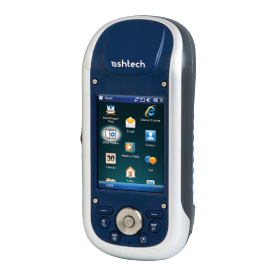
System Description Receiver Front Display Screen View The display screen [1] is a 3.5-inch QVGA color touch screen (240 x 320 pixels). Keypad, Scroll and Enter Buttons The keypad [2] consists of the following buttons: Button Function The keypad includes two of these buttons, one on the right, the other on the left. -
Page 12: Receiver Rear View
Built-in GSM Antenna [8]: Location of the built-in GSM antenna used for mobile communications. Built-in Bluetooth Antenna [9]: Location of the built-in Bluetooth antenna for wireless communication with nearby Bluetooth-fitted equipment. Receiver Rear View Camera Lens [10] [11] Keep the camera lens [10] clear when taking pictures or recording videos. -
Page 13: Receiver Bottom View
Power & Battery LED The three-color LED [15] gives indications on the receiver power status, and on the battery state, in relation with the use of the docking station. Please refer to LED Indicator on [17] page 13 for more information on the LED indications. SD Card Slot [15] [14]... - Page 14 receiver as well as an additional battery placed at the back of the docking station. When two batteries are charged simultaneously, fast charging (< 4 hours) is for the battery in the receiver and slow charging (about 11 hours) for the spare battery located at the back of the docking station.
- Page 15 Rear View [21] [22] [23] [24] [25] [26] The following elements can be found at the rear of the docking station: • Back slot [21] for charging a second battery • Charging indicator [22] for back slot: – Steady red: Battery charging in progress –...
-
Page 16: Special Features
Special Features Power Modes The receiver can be powered from one of two different sources: • Its internal battery (typically for field operations) • The power line, through the AC adapter and the docking station (typically for office work). These two items are part of the basic supply. -
Page 17: Led Indicator
LED Indicator The tables below summarize the different statuses reported by the Power/Charging LED [1]: Table 1. Standalone Receiver Power Mode Indication Green a few seconds at power on, then off. Green flash every 5 seconds. Suspend Table 2. Receiver on Powered Docking Station, Normal Statuses LED Indication Power Mode Internal Battery Status... -
Page 18: Gprs Connection Using The Internal Modem
Suspend mode, meaning the battery is no longer charged enough to ensure proper operation of the receiver. Ashtech recommends you do not go that far in the use of the internal battery as this may irreversibly damage it. - Page 19 Inserting a SIM Card Remove the battery door and the battery to access the SIM card holder. Refer to the figure below to insert the card. The holder should be opened before you can place the SIM card. Make sure you properly lock the SIM card holder before putting back the battery and locking the battery door.
-
Page 20: Cdma Connection Using An External Mobile Phone
• Tap Next (bottom of the screen). • Enter the Access point name. This information should have been passed on to you by your ISP. • Tap Next. • Enter the following information, also passed on to you by your ISP when purchasing the SIM card: –... - Page 21 It is therefore the SIM card inserted in the mobile phone that will control the connection to the network, and not the receiver itself. The receiver does not need a SIM card and its phone function can stay off. Note that this type of network connection cannot be combined with Microsoft ActiveSync used in a USB connection between the receiver and a local computer.
- Page 22 • When the Bluetooth connection is established, the receiver screen lists the Bluetooth services available from your mobile phone. Make sure the Dialup Networking option is enabled. • Tap Save to complete the connection procedure. This takes you back to the Bluetooth Settings window on which you can now see your phone as a properly connected unit.
-
Page 23: Using The Camera
Using the Camera Taking a Picture • Tap Start and Pictures & Videos. This opens the “My Pictures” folder in which you can see the list of existing images and videos. The first item in the list is the Camera, the tool you will now be using to take pictures. -
Page 24: Making A Video
happy with the result, you can always come back to the initial image by selecting Menu and Revert to Saved. • Tap OK to save the picture. Auto-correcting a Picture • With the “My Pictures” folder open, tap on the desired picture (or tap on View in the task bar). - Page 25 • Tap within the Time limit... field and select one of the options below: – No limit: Choose this option to be able to film a video over an unlimited period of time. – 15 seconds: Choose this option to limit the duration of every video you’ll film to 15 seconds.
-
Page 26: Using Windows Mobile 6.5
Note that although made extremely visible on the Start screen, the Phone function inherited from Windows Mobile 6.5 CANNOT be used in voice mode on this Ashtech platform. The Phone function should however be activated when a GPRS connection is required in such differential modes as Direct IP or NTRIP (see Differential Mode on page 63). -
Page 27: Using Mobilemapper Field Software
ActiveSync 4.5 and Device Center 6.1 can be installed directly from your MobileMapper Field CD. If you are upgrading MobileMapper FIeld, Ashtech recommends you first uninstall the previous version of Start, Settings, MobileMapper Field from the receiver using System, Remove Programs. -
Page 28: Getting Started With Mobilemapper Field
MobileMapper Field CD box. This code was generated from the serial number you provided to Ashtech when ordering the software. To enter the activation code: • Tap on the “MobileMapper Field” line on the start screen. - Page 29 Description of the MobileMapper Field Main Window [12] [11] [10] • [1]: Number of satellites currently used in position computation; current value of PDOP; “DGPS” when the receiver is operating in SBAS differential mode; and “REC” if the raw data logging option is unlocked and active.
- Page 30 button or the MENU key on the keyboard to show or hide the function menu. Menu Option Function Pause Use this option to pause the current feature logging. Stop Use this option to stop the current feature logging. Layers... Use this option to add, modify or remove layers. Use this option to find a feature previously logged in the Find...
- Page 31 • Area units: Choose between square meters, square kilometers, hectares, acres, square feet, square yards or square miles. 2. Tap on the Antenna tab and then enter the vertical distance you will maintain between the top of the receiver (where the GPS antenna is) and the ground while executing the job.
-
Page 32: Creating A New Job
Caution! Tapping in the upper-right corner of the screen only minimizes the MobileMapper Field window and so does not fully exit the program. Creating a New Job During your First MobileMapper Field Session After entering the activation code, MobileMapper Field displays the map screen. -
Page 33: Creating New Layers
“Storage Disk” (resident memory), or “Storage Card” (if there is an SD card inserted in the receiver). 3. Tap Save to create the job file. What you then get on the screen depends on the format (map or dxf) you chose for the job. - Page 34 – An SHP layer can only contain a single type of feature. When creating a new layer, you should first indicate if it is created to hold 2D/3D point, 2D/3D line or 2D/3D polygon features. – A MIF layer can contain any type of feature (point, line or polygon).
- Page 35 new folders in the “My Documents” folder, in the “Storage Disk” folder or on the storage card. It is highly recommended to create layers in the same folder as the job file using these layers. Observing this rule will simplify the download procedure. •...
- Page 36 5. The program now asks you to define the properties of the layer. The table below summarizes the different properties you should define for the layer, according to its type. 2D or 3D 2D or 3D 2D or 3D Properties Csv layer Point Line...
- Page 37 Layer Properties Symbol. 57 different symbols are available to represent a point feature on the map screen. Color. 15 different colors are available to represent a line feature or the contour of a polygon feature on the map screen. Style. The line style (thin, medium, thick or dash) is used to represent a line feature on the map screen.
- Page 38 Some useful attributes with preset names are displayed for each layer type (see table below). It’s up to you whether or not to create them. Attribute Attribute Point Line Polygon MapInfo Name Type Layer Layer Layer layer Picture Image • •...
-
Page 39: Adding Existing Layers To A Map Job
Showing/Hiding Features on the Map Screen • Tap Menu>Layers... • Enable or clear the check box placed before each layer name to respectively show or hide the layer on the map screen. Showing a layer means showing all the features logged in that layer. - Page 40 Georeferencing may have been done earlier using a third- party tool. Georeferencing can also be done after adding the background map. This can be done in two different ways: 1. You know the coordinates of the reference points used to georeference the image.
- Page 41 receiver can compute a position. Remember you may also have to press the ESC button so that the map screen can show the location of the first logged feature. Georeferencing an Image File Georeferencing an image file means defining at least three reference points giving the position of the image in space.
-
Page 42: Logging New Features
the reference points you incorrectly created on the background map will all be deleted. Try again, this time with correct point location and coordinates. • It is highly recommended to place the original image file used to create the background map in the same folder as the job file using it. - Page 43 In Manual mode, you stop at each of the vertices ( on which the receiver computes a position averaged over n seconds Automatic Manual Continuous lines show actual paths traveled. Dotted lines show features, as logged. • On the Offset tab, you can set: –...
- Page 44 the feature. By doing this, you will place the feature at the center of the map screen. Prerequisites • The receiver is on and MobileMapper Field running. • A Map job is used, which contains three SHP layers: a point layer named “Points”, a line layer named “Lines” and a polygon layer named “Areas”.
- Page 45 measurements. This action will automatically fill in the Bearing and Horizontal Distance fields. If no range finder is used, type an estimate of the horizontal distance directly in the field using the keyboard. The better you estimate the distance, the better the collected position.
- Page 46 – Direction: this parameter tells the program whether the real feature is on your left or right. Left – Horizontal Distance field: Horizontal distance perpendicular to the line or polygon feature. If a range finder is used to measure this distance, tap on the Read Range Finder button once the range finder Right has got a valid measurement.
- Page 47 • For a numeric attribute, type your number using the virtual keyboard and then tap OK. • For an image attribute, the following menu is displayed: – Camera: Runs the camera utility so you can take a picture. For more information on using the built-in camera, see Using the Camera on page NOTE: Picture attributes are saved as JPG files in the...
- Page 48 1: Drags the recorder bar. 2: Starts voice recording. 3: Pauses voice recording. 4: Plays back voice recording. 5: Stops voice recording. 6: Closes the recorder bar – Play: For check purposes, select this function to play back the voice message you’ve just recorded (equivalent to “4”...
- Page 49 • Later when you are ready to resume data logging, go back to where you left the line or polygon, tap Menu>Resume to continue the data logging as you walk along the feature. Double Logging While logging a line or polygon, you may want to log another feature found along the way, whether a point, a line or a polygon.
-
Page 50: Revisiting Features
– Run File Explorer – Delete unnecessary files – Return to MobileMapper Field and stop logging the feature. The feature will normally be saved if enough memory space has been cleared. Deleting Features For some reason or other, you may want to delete a feature, whether a point, a line or a polygon. - Page 51 Whatever the method used, you can now see, on the map screen, a yellow/red segment connecting your current position to the feature. For a line or polygon, MobileMapper Field will draw a segment between your current position and the point in the line or polygon the nearest to you.
-
Page 52: Upload/Download Functions
Upload/Download Using the USB data cable provided with your receiver, you can exchange data between the receiver and your office Functions computer. With Vista running your computer, no particular settings are required. With Windows XP (or older), use the following settings in ActiveSync to make the connection automatic at receiver power up:... -
Page 53: Coordinate Systems
Coordinate When creating a new DXF job or when creating a layer as the first layer in a new *.map job, MobileMapper Field asks you Systems to define a coordinate system. Choosing a Coordinate System Proceed in this order: 1. Choose the World Geodetic System or the country where your field operations will take place 2. -
Page 54: Voice Setting
it as the system used in the current job. This will take you back to the coordinate system selection screen on which you will now be able to see how the new USER coordinate system has been defined (new projection and datum names displayed in the second and third fields respectively). -
Page 55: Post-Processing Option And Mobilemapper Office
• Enable the Record raw data for post-processing option. • Tap OK. A new screen is displayed showing the serial number of your receiver and a blank activation code field. • Type the activation code provided by Ashtech in the blank field. • Tap to validate the code entry. -
Page 56: Installing Mobilemapper Office Software
Raw data can only be saved in the internal memory, in the “Storage Disk” folder. The raw data files will be found in the “GNSS Raw Data” sub-folder. • Raw data files are named as follows: nnnnyymmddss.grw Where: Parameters Description nnnn Last four digits of the receiver serial number Last two digits of year (“08”... -
Page 57: Post-Processing With Mobile-Mapper Office Software
– Microsoft .NET Framework 2.0 – Microsoft Visual C++ Runtime Libraries – Microsoft Windows Installer 3.1 • The installation program then installs MobileMapper Office. • At the end of the installation, MobileMapper Office is automatically launched. Post-Processing • Using the data transfer procedure (see Upload/Download Functions on page 48), copy the following field data files With Mobile- from... - Page 58 The different areas are described below: – [1]: Open/Create Map button – [2]: Menu bar – [3]: MAP filename and Layers list – [4]: Map screen showing the content of the open job, Also includes zoom buttons on the left and distance/ angle/area tool buttons on the right.
- Page 59 – [6]: Observation times covered by the raw data files added to the project. A green bar stands for a receiver raw data file, and a yellow bar, for a base raw data file. and select Open. Browse to the folder •...
- Page 60 • Click Download. MobileMapper Office imports the base raw data and then show its properties in areas [5] and [6]. NOTE: Ashtech does not guarantee 100% quality results when using raw data files from reference stations that are situated beyond 200 km (125 mi) from your working area.
-
Page 61: Quality Control In Post-Processing
Quality Control in You can place a quality control filter through which MobileMapper Office will rate the post-processing results Post-Processing according to your own requirements. Following the post- processing of your job, MobileMapper Office will associate the resulting vectors to two different layers: one containing the vectors that passed the quality control (green vectors), and a layer containing those that failed (red vectors). -
Page 62: More About Mobilemapper Office
• Google Earth format (*.kml). All the selected layers will be merged into a single kml file. Opening a kml file from the Google Earth initial view will cause the Earth representation to be gradually rotated and zoomed in to show the exact location of the features held in the kml file. - Page 63 • Zoom settings: In addition to the zoom buttons in the menu bar and on the map screen, MobileMapper Office offers another useful way of adjusting the zoom setting. Double-click on a feature in the map screen. This takes the feature to the center of the map screen. You can then adjust the zoom setting around the feature, which stays at the center of the screen, using the mouse wheel (turn forward to zoom in, turn backward to zoom out).
- Page 64 For each tool, the first click on the icon will activate the tool and change the cursor shape. The second click will turn off the tool and the cursor will recover its initial shape. Distance measurement: – Click on the first point from where to start the distance measurement.
-
Page 65: Post-Processing Demo
Internet or if they come from a reference station that is not connected to the Internet, like for example an Ashtech ProMark3 base. In either case, click on Add Reference Raw Data>From File and select the base raw data files. -
Page 66: Gnss Toolbox
– Select this option from the Option field – Enter the activation key in the Key field. This key was provided by Ashtech after you purchased this option. – Tap OK to complete the installation of the option, which will then appear in the list of installed options. -
Page 67: Gnss Settings
GNSS Settings • Open the GNSS Toolbox and tap on GNSS Settings. This opens a new window where you can make the following settings: – Tracking mode: Depending on the installed firmware options, one or more combinations of constellations and frequencies may be listed here. Choose the suitable one. -
Page 68: Nmea Output
Connection Using an External Mobile Phone on page 16 for CDMA. Connect to Network .. ISP data required: APN, user, password,.. Modem connection used: via Bluetooth ISP data required: APN, user, password,.. Modem connection used: Cellular line (GPRS) Bluetooth Connection between Receiver and External CDMA Mobile Phone Activate Phone function Insert SIM card... -
Page 69: Reset
The default Position tab shows the latitude, longitude and altitude of the current position, as computed by the receiver, as well the number of satellites used and the current PDOP value. If SBAS is used, the screen also shows the position computation mode used and the age of corrections. -
Page 70: Troubleshooting
(e.g. “ATL_100715_162514.log” for a file logged on July 15, 2010 at 4:25:14 pm) • Send an email to Ashtech Technical Support with this file attached to the email. The file uses a proprietary format and so can only be parsed by Ashtech. -
Page 71: Turn Off Gnss
• Open the GNSS Toolbox and tap on Turn off GNSS. The Turn Off GNSS message “Power off GNSS receiver?” is displayed asking you to confirm or cancel your power-off request. • Tap Yes to confirm. This will instantly turn off the GNSS section of the receiver and take you back to the Start screen. -
Page 72: Installing Geoids
Installing Geoids Ashtech makes available a collection of geoids for use in many countries around the world. This collection is hosted on the Ashtech website and is regularly updated. To download a geoid, use the Geoids (models & tools) option in the welcome menu of the MobileMapper Software CD delivered with the receiver. -
Page 73: Platform Specifications
– L1 C/A – SBAS: WAAS/EGNOS/MSAS • Ashtech BLADE technology for optimal performance • DGPS, RTK and post processing with Ashtech software • Up to 20 Hz GPS, GLONASS, SBAS position output and raw data (code and carrier) • NMEA 183 messages output •... -
Page 74: Communication
Communication Cellular: • Built-in GPRS, EDGE class 12 modem • Quad-band, 850/900 MHz, 1800/1900 MHz Bluetooth: • Bluetooth 2.1 (class 2) with DER • Profiles: SPP, DUN, FTP, OPP, HSP, A2DP Other: • RS232, USB through docking station • Wireless LAN 802.11b/g (SDIO slot) Physical •... -
Page 75: Power Requirements
Power • Removable battery: Li-Ion, 6600mAh Requirements • Battery life: > 8 hours @ 20 ºC, with GNSS on and Bluetooth, WLAN and screen backlight disabled. • Battery charging time: 3 hours (in standalone or with turned-off receiver) • External power: 9-28 V DC Multimedia &... - Page 76 Index Symbols Fill Filter settings (quality control) *.dxf file Find feature function *.map file Framework 2.0 *.shp files Freezing layer definition Activation code Georeferenced file ActiveSync GeoTIFF Add Reference Raw Data Add Rover Data GNSS settings Adjusting backlight GNSS Toolbox Antenna Go to Area...
- Page 77 Stop shooting video Minimizing MobileMapper Field Storage Card (SD card) Mobile phone Style MobileMapper Office Stylus Symbol North up Numeric Target coordinates Text Time limit (video) Observation times Timer Opening battery door Type (of feature) Operating system OPP (Object Push Profile) Unlock post-processing Upload PDOP...
- Page 78 Ashtech follows a policy of continuous product improvement; specifications and descriptions are thus subject to change without notice. Please contact Ashtech for the latest product information. © 2010 Ashtech. All rights reserved. The Ashtech logo and MobileMapper are registered trademarks of of Ashtech LLC. All other product and brand names are trademarks of their respective holders.
Need help?
Do you have a question about the MobileMapper 100 and is the answer not in the manual?
Questions and answers