Table of Contents
Advertisement
Quick Links
Advertisement
Table of Contents

Related Manuals for ashtech ProFlex 500


Summary of Contents for ashtech ProFlex 500
- Page 1 ProFlex ™ Reference Manual...
- Page 2 RF Energy. FCC Notice SAR was measured with the unit (GSM Module) ProFlex 500 Receiver complies with the limits for a transmitting at its maximum certified RF power. Of- Class B digital device, pursuant to the Part 15 of the ten, however, during normal operation the unit (GSM FCC rules when it is used in Portable Mode.
- Page 3 (ii) disasters such as fire, flood, wind, and lightning; (iii) unauthorized attachments In the event of a defect, Ashtech will, at its option, or modification; (5) service performed or attempted repair or replace the hardware product with no charge by anyone other than an authorized Ashtechs Service to the purchaser for parts or labor.
- Page 4 Ashtech SAS - ZAC La Fleuriaye - BP 433 - 44474 EXCEPT AS SET FORTH IN ITEM 1 ABOVE, ALL Carquefou Cedex - France Phone: +33 (0)2 28 09 OTHER EXPRESSED OR IMPLIED WARRANTIES, 38 00, Fax: +33 (0)2 28 09 39 39.
- Page 5 French Civil Code). For further information concerning this limited war- ranty, please call or write: Ashtech - ZAC La Fleuriaye - BP 433 - 44474 Car- quefou Cedex - France. Phone: +33 (0)2 28 09 38 00, Fax: +33 (0)2 28 09 39 39.
- Page 6 Chapter 3 updated to reflect all the option, changes made to the Web Server. • “Flying RTK” firmware option, • Chapter 4 about ProFlex 500 CORS • Backup FTP server, updated to cover the new features (backup FTP server, embedded NTRIP •...
- Page 7 Chapters 5 to 9 cover all the topics relevant to the use of the ProFlex 500 in RTK land sur- Chapters 16 and 17 are grouped together to veying applications, either as a temporary constitute the Appendix of the manual.
-
Page 9: Table Of Contents
Physical and Virtual Ports ............38 Chapter 2. Using the ProFlex 500 Web Server ........39 Introduction................39 Getting the ProFlex 500 Ready for Running the Web Server ..40 Setting a Rover ...............47 Setting a Base .................66 Creating an Account on DynDNS.com.........86 Configuration Memo ..............87... - Page 10 System Configuration..............294 Static Survey .................298 “Stop & Go” Kinematic Survey ..........300 Continuous Kinematic Survey ..........302 Chapter 10. Integrating ProFlex 500 into Your Application ....305 Installation Instructions ............305 Manual Configuration Steps: Introductory Notes ......310 Rover Using Internal Radio .............312 Rover Using Port A as Corrections Input ........313 Rover Using Port B or F as Corrections Input ......314...
- Page 11 Setting Up the Ethernet Connection .........331 Using the ProFlex 500 Ethernet Port........333 Chapter 12. Using Serial Commands ..........339 Introduction to Serial Commands ..........339 Applying Commands Through Bluetooth or a Serial Port .....340 Applying Commands Through TCP/IP ........342 Running Serial Commands from a USB Key ......345 List of Commands ..............348...
- Page 12 CTS: Handshaking ..............396 DBN,TYP: DBEN Message Type & Output Rate......397 DDN,PAR: Setting the DynDNS Service ........398 DDN,SET: Sending the IP Address Manually to DynDNS ....399 DIP: Server Connection ............400 DIP,OFF: Terminating Direct IP Connection ......401 DIP,ON: Establishing the Programmed Direct IP Connection..402 DIP,PAR: Setting Direct IP Parameters ........402 DRI: Raw Data Recording Rate ..........404 DST: Data Stream Connection Modes ........405...
- Page 13 PWR,OFF: Powering Off the Receiver ........457 PWR,PAR: Power Management ..........457 RAW: Enabling/Disabling Raw Data Messages in Legacy Ashtech Format ............458 RAW,ALL: Disabling All Raw Data Messages ......460 RAW,PER: Setting Unique Output Rate for Raw Data....460 RCP,GBx: GLONASS Carrier Phase Biases for User-Defined Receiver ................461...
- Page 14 SES,ON: Starting Sessions ............487 SES,OFF: Stopping Sessions ...........487 SES,PAR: Session Recording Parameters........488 SES,SET: Setting Sessions Manually ........491 SIT: Defining a Site Name............492 SNM: Signal-To-Noise Ratio Mask..........492 SOM: Masking Signal Observations ..........494 SOM,CTT: Cumulative Tracking Time Mask .......495 SOM,NAV: Navigation Data Mask ..........496 SOM,SNR: Signal-to-Noise Ratio Mask ........498 SOM,WRN: Channel Warnings Mask .........499 STI: Defining a Station ID ............501...
- Page 15 BEEP: Beeper State ...............535 BRD: RTC Bridge ..............536 BTH: Bluetooth Settings ............536 CMR,MSI: CMR Message Status ..........537 CP2,AFP: Ambiguity Fixing Parameter, Second RTK Engine ..538 CPD,AFP: Ambiguity Fixing Parameter........539 CPD,ANT: Base Antenna Height..........539 CPD,FST: Fast RTK Output Mode ..........540 CPD,MOD: Base/Rover/Backup Mode ........541 CPD,NET: RTK Network Operation Mode ........543 CPD,POS: Base Position ............544 CPD,REM: Differential Data Port..........545...
- Page 16 LOG,PAR: Log File Settings .............584 MDM: Modem Status and Parameters........584 MDM,LVL: Modem Signal Level ..........586 MDP: Port A Setting ...............586 MEM: Selected Memory Device..........587 MET: Meteorological Unit Settings ...........588 MWD: Modem Watchdog Timeout ..........588 NMO: NMEA Message Output Settings ........589 NPT: Tagging of SBAS Differential Positions in NMEA &...
- Page 17 SGP: GPS & SBAS Satellites Status .........635 SIT: Site Name ..............637 SNM: Signal-to-Noise Ratio Mask ..........638 SOM: Signal Observations Masking ..........639 SOM,CTT: Cumulative Tracking Time Mask.......640 SOM,NAV: Navigation Data Mask ..........640 SOM,SNR: Signal-to-Noise Ratio Mask ........641 SOM,WRN: Channel Warnings Mask.........642 STI: Station ID...............643 SVM: Satellite Use Mask............644 TCP: TCP/IP Server Settings ............644...
- Page 18 Problem to Ashtech Tech Support .........693 List of Alarms ...............694 Chapter 17. Other Procedures & Memos ......... 705 Special Button Combinations Summary ........705 Reset Procedure ..............705 Firmware Upgrade Procedure...........705 Time-tagged RTK vs. FAST RTK Position Output ......707 ATOM File Naming Conventions ..........707 Changing the Radio Module.............709...
-
Page 19: Chapter 1. Receiver Description
• The use of ProFlex 500 can also be extended to those terrestrial applications, like machine guidance or machine 1. GNSS= Global Navigation Satellite System. -
Page 20: System Components Overview
Ashtech ProFlex 500 is proving to be the best system available today for this kind of requirement. • As an extension of the ProFlex 500, ProFlex 500 CORS is an advanced CORS reference station for use in the most demanding applications. - Page 21 Part Number Picture Serial data cable 700461 Multi-function cable, 7C circular connector, bare 702450 wires, length: 3 m approx. (ProFlex 500 CORS) Soft transport bag 206410 AC/DC Power Supply Kit (includes external AC adapter, battery charger and cable extension for 802064...
- Page 22 Receiver Description Item Part Number Picture See table on Choice of radio receiver kits Refer to page 5 page 5 See table on Survey Backpack kit 890309 page 5 See table on Machine Installation & Connectivity kit 802089 page 6 See table on UHF accessory kit (30 meters) P0101390...
- Page 23 Receiver Description Optional Receiver Kits Item Part Number Picture U-Link Rx, 12.5 kHz channel 802081-10 (410-430MHz) bandwidth (includes whip 802081-30 (430-450 MHz) (internal part) antenna). 802081-50 (450-470 MHz) PDLRXO receiver kit, 25-kHz 802087-35 (430-450 MHz) channel bandwidth (includes whip (Internal part) 802087-55 (450-470 MHz) antenna).
- Page 24 700439 External DC Power Cable for Receiver (fuse 730477 included) USB-Device-to-PC Cable, 1.5 m. 702103 Makes ProFlex 500 a USB host. Multi-function serial cable 702443 Low-loss LMR-240GPS/GNSS cable, 30 702455 meters, TNC male / TNC male N-m/N-m, 50-ohm, KX13 coaxial cable,...
- Page 25 Receiver Description Item Part Number Picture Screw H UNC5/8-11, for fixing GNSS antenna 206262 (Small part) fitted with 5/8” tapped hole onto P/N 111407. UHF Accessory Kit (30 meters) Item Part Number Picture TNC-m/TNC-m, KX15 coaxial cable, 1 meter, C5050156 + N-f/TNC-f coaxial adaptor C5050216 Low-loss LMR-240GPS/GNSS cable, 30...
-
Page 26: Equipment Description & Basic Functions
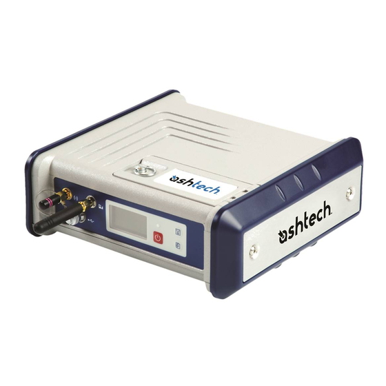
Receiver Description UHF Accessory Kit (10 meters) Item Part Number Picture TNC-m/TNC-m, KX15 coaxial cable, 1 meter, C5050156 + N-f/TNC-f coaxial adaptor C5050216 N-m/N-m, 50-ohm, KX13 coaxial cable, P0101131 10 meters UHF antenna, 3 dB (CXL70-3 C/L) C3310145 Equipment Description & Basic Functions Front View From left to right:... - Page 27 1. For a USB host, such as a mass storage device using optional device cable P/N 702103. 2. For a USB device allowing ProFlex 500 to be seen as a disk from the computer connected to this port. In this configuration, files can be transferred between the ProFlex 500’s internal memory and the computer using...
- Page 28 “Ashtech” screen is displayed. Then release the button and wait until the ProFlex 500 shuts down. Power LED • This indicator light is off when the ProFlex 500 is off and no external power source is connected to the DC power input.
- Page 29 DC Power Input A Fischer, three-contact, female connector [1] allowing the ProFlex 500 to be powered from either the provided AC adapter (connect the cable extension between ProFlex 500 and the end of the AC adapter output cable), or an external 9- to 36-V DC power source through cable P/N 730477 (cf.
- Page 30 ProFlex 500 has been fitted with a radio module. Ethernet Port A Fischer, seven-contact female connector [7] allowing you to connect the ProFlex 500 to a local network (LAN). Through this connector, you may remotely control and monitor the ProFlex 500 from any computer connected to the Internet.
- Page 31 It is a standard model used in many camcorders. The battery is housed in a battery compartment accessible from above the ProFlex 500. The compartment door can be opened by lifting and then turning the quarter-turn finger screw counter-clockwise.
-
Page 32: Display Screens
Use for example the tip of a pen to slide the switch to the left or right. Special Button • With the ProFlex 500 OFF, pressing the Power, Log and Scroll buttons simultaneously for a few seconds will Combinations restore all the factory settings. - Page 33 Receiver Description [10] [11] [12] [13] This screen displays the following information: • : Satellite icon [1] (always displayed). • Number of satellites tracked [2]. • Position solution status [3]: – NONE: Position not available – AUTO: Autonomous GPS position –...
-
Page 34: External Power Source
Receiver Description • Percentage of free memory in the storage medium used [8]. • : Battery icon [9] with visual indication of remaining charge. If an external power source is used (AC adapter or external battery), the battery icon will be animated to indicate battery charging in progress. - Page 35 Receiver Description • [13]: USB status and/or Bluetooth status and/or Ethernet port status. Icon Definition USB port connected to active device Bluetooth active Ethernet port active These three icons will appear successively when the USB port, the Ethernet port and Bluetooth are all active. Blank USB port unconnected, Bluetooth and Ethernet inactive.
- Page 36 Receiver Description • Where placed, it indicates that this storage medium is used for data logging. What if there is no USB mass storage device connected to the receiver? • Parameters relevant to the USB key size and space used and available are void (three dots displayed instead).
-
Page 37: Charging Batteries Before Use
Screen page 291. Charging Batteries Before Use Make sure the battery is fully charged for each ProFlex 500 you will be using in the field. For a ProFlex 500 CORS, inserting a fully charged battery into the receiver will guarantee that the station can keep operating for several hours after a power shutdown, giving you the time to take the necessary maintenance steps. - Page 38 Battery from the • Open the battery trapdoor, accessible from above the ProFlex 500 ProFlex 500, by lifting and then turning the quarter-turn finger screw anticlockwise. This releases the two springs located under the battery, pushing the battery slightly upward (see picture).
- Page 39 (the battery terminals Battery in the should come into contact with the two sets of connectors ProFlex 500 located at the bottom of the compartment). • Close the trapdoor, push the finger screw in tight, and turn it fully clockwise.
-
Page 40: Specifications
– Quick signal detection engines for fast acquisition and re-acquisition of GPS/GLONASS/SBAS signals. – Fully independent code and phase measurements • Ashtech BLADE™ technology for optimal performance • Advanced multipath mitigation • Up to 20 Hz raw data and position output •... - Page 41 Receiver Description • Horizontal < 50 cm typical DGPS • Horizontal < 30 cm typical • 95%: 90 cm (2.9 ft) Flying RTK™ • Within 50 km of baseline: 5 cm + 1 ppm. (1)(2). • Beyond 50 km of baseline: 20 cm + 1 ppm. (1)(3). •...
- Page 42 Receiver Description • Horizontal: 3 mm (0.009 ft) + 0.5 ppm • Vertical: 6 mm (0.019 ft) + 0.5 ppm Post-Processed Kinematic: • Horizontal: 10 mm (0.033 ft) + 1.0 ppm • Vertical: 20 mm (0.065 ft) + 1.0 ppm Data Logging Recording Interval Characteristics...
-
Page 43: Marker Input
Receiver Description • 1 or 2 internal NTRIP servers can connect to it as independent sources of correction data. • Includes mechanism to automate the use of DynDNS.com (for automatic recognition of the receiver through its dynamic IP address). Full MET/TILT •... -
Page 44: Firmware Options
Receiver Description Power Requirements Characteristic Li-ion battery, 32.5 Wh (7.4 V x4.4 Ah). Ensures UPS Internal, removable (Uninterrupted power supply) in case of power outage battery (Back-up battery) Internal battery life time > 6.5 hrs (UHF rover at 20°C) External power input Isolated, 9-36 V DC input Power requirement <... - Page 45 Receiver Description Designation Description Allows a base to generate and send RTK cor- rections. Allows a rover to compute RTK position solu- 680502 tions using corrections received from a base (unlimited RTK). RTK3 For a rover, limits the RTK range to 3 km. 680581 Enables a base receiver to generate RTCM, N STA...
-
Page 46: U-Link Radios
• Two transmitter status LEDs (Type of RS connection, data transfer, repeater mode) Configuration tool: • Ashtech radio configuration software used to set channels and output power • Up to 16 channels can be saved in the radio • Radio output power : 0.5 W, 2 W or 4 W Power requirements: •... - Page 47 • Serial link: RS232 • Up to 16 channels can be saved in the radio • Adjacent channel power: > 60 dBc • Ashtech radio configuration software used to set channels. Configuration Tool: • Ashtech radio configuration software used to set channels...
- Page 48 The central frequency of the U-Link Rx can be read inside the battery trapdoor of your ProFlex 500. The central frequency of both the U-Link TRx and U-Link Rx can be read using the $PASHQ,RDP,PAR command (the central frequency setting is the last parameter in the response line).
-
Page 49: Uhf Data Link Compatibility Table
ON= Transmitter ON= RS422 Power UHF Data Link Compatibility Table Interoperability between Ashtech and PacCrest radios is presented in this section. In the two tables below, “Yes” means the corresponding combination of radios is possible, “No” means the opposite. The 25-kHz channel spacing is usable with PacCrest radios only. -
Page 50: Port Pinouts
PacCrest U-Link Rx Yes; Base using PacCrest Transmitter Transparent protocol Base using Ashtech radio trans- mitter (old model) Base using U-Link TRx Any combination of radio devices using different channel spacing will not work. Generally speaking, a non-hybrid combination of radios is recommended. -
Page 51: Marker Input
Receiver Description 3-C Connector, Type: Fischer DPUC 102 A052-130, fitted with sealing cap. Signal Name Description External Power Ground External Power Input (9-36 V DC) Serial Data Ports Ports A, B and F on rear panel. Three 7-C connectors, Type: Fischer DPUC 102 A056-130, each fitted with a sealing cap. - Page 52 Receiver Description RS422 Configuration (port A only): Signal Name Description +12 V DC 12-V DC Output Ground RXD- Receive Data- TXD+ Transmit Data+ RXD+ Receive Data+ TXD- Transmit Data- 1PPS output Port A can be switched to RS232 or RS422 using the $PASHS,MDP command.
- Page 53 Receiver Description Fischer S102-A056 DB15 or equivalent RTS/TXD+ TXD/TXD- RXD/RXD+ CTS/RXD- +12 V DC Shield 1PPS/Event Shield Ethernet Port On rear panel. 7-C Connector, Type: Fischer DPUC 102 A056-230, fitted with sealing cap. Although being also a 7-contact type, this receptacle uses a positioner that is different from the one used on ports A, B and F, thus making impossible the connection of the serial cable provided to this port.
-
Page 54: 1Pps Output
Receiver Description Signal Name TX-S TX+S CAN Bus On rear panel. For use in a future release of the product. 5-C Connector, Type: Fischer DPUC 102 A054-130, protection cap provided. Signal Name Description NET-SHIELD Shield NET-S Power source (+) NET-C Power source (common) NET-H “High”... -
Page 55: Event Marker Input
Receiver Description GPS time 1PPS with Offset= 0 1PPS with Offset= + x.x sec 1PPS with Offset= - x.x sec • Active edge, i.e. the edge (falling or rising) synchronized with GPS time. (On the diagram above, the rising edge was set to be the active edge) You can read the current properties of the 1PPS output using the $PASHR,PPS command. -
Page 56: Physical And Virtual Ports
Receiver Description The signal specifications of the marker event input are the following: • Signal level: ± 10 V • Permitted transient time on active edge: < 20 ns Physical and Virtual Ports Port ID Port Definition External serial port (RS232/RS422) External serial port (RS232) Bluetooth SPP Internal UHF radio... -
Page 57: Chapter 2. Using The Proflex 500 Web Server
Chapter 2. Using the ProFlex 500 Web Server Introduction What is the ProFlex 500 Web Server and what is it for? The ProFlex 500 Web Server is a receiver-embedded, HTML- based firmware application designed to enable users to monitor or control the ProFlex 500 through a TCP/IP connection. -
Page 58: Getting The Proflex 500 Ready For Running The Web Server
Ix (data streaming). Getting the ProFlex 500 Ready for Running the Web Server This section is more particularly intended for the receiver owner, who is also the receiver administrator. - Page 59 Using the ProFlex 500 Web Server TCP/IP Connection In this case of use, the receiver and the computer are connected to the same local area network (LAN) and may Within a Local even be in the same room. Here the communication will NOT...
- Page 60 Switch In this configuration, the IT Manager should take all the necessary steps for users to be able to access the ProFlex 500 through the public IP address of the local network. Obviously, the IP address read on the receiver display screen is NOT the one to be provided to users.
- Page 61 Using the ProFlex 500 Web Server “Direct” TCP/IP The term “Direct” used here should not be confused with the “Direct IP” connection mode, which is a special case of Connection Internet connection to a static IP address. Here the term “Direct”...
- Page 62 Using the ProFlex 500 Web Server Bluetooth (see ProFlex 500 Reference Manual, Using Serial Commands Chapter, for more information) $PASHQ,ETH Example of receiver response: $PASHR,ETH,I,ON,00:09:66:00:10:a0,10.20.2.123,DHP=1,ADD=192.168. 0.1,MSK=255.255.255.0,GTW=255.255.255.255,DN1=255.255.255.255,D N2=255.255.255.255*3F Should the Ethernet port be off (2nd parameter in the above response line is “OFF” instead of “ON”), please use...
- Page 63 Using the ProFlex 500 Web Server 10.Enter a different IP address for the computer (e.g. 10.20.2.2). Enter the same subnetwork mask and gateway as those entered above in the receiver through the $PASHS,ETH,PAR command. 11.Click OK twice to close the windows.
- Page 64 You should inform your IT Manager of the following before he/ she can set up the connection: the Receiver • The ProFlex 500 is not fitted –and cannot be fitted– with Administrator & IT a firewall. If a firewall is needed in your local network, it...
-
Page 65: Setting A Rover
Enter key. After the connection has successfully been established, the ProFlex 500 Web Server Home tab appears in your web browser. 5. Click on the Status tab. You are then asked to enter the login and password of your connection profile (user or administrator). - Page 66 Using the ProFlex 500 Web Server – Ambiguity Fixing: Set the confidence level (percentage) controlling the ambiguity fixing process. The available choices depend on the firmware options installed: “RTK2” ([M]) or/and “RTK3” ([L]) installed: Several percentages are available. Choosing a high percentage will result in a highly reliable process but is liable to reduce the availability level of “fixed”...
- Page 67 Using the ProFlex 500 Web Server parameter in the selected distance unit. See also the diagram and table below for more information. – SHMP Offset: In case of a “Slant Height” measurement, enter the SHMP offset (this is a manufacturer specification) taking care to enter this parameter in the selected distance unit.
- Page 68 Using the ProFlex 500 Web Server satellites as well. Enable the options corresponding to the additional constellations you want the receiver to use. • You can now click on the Configure button to save all the changes made but remember you have to complete the content of this page depending on how the receiver will get its RTK corrections.
- Page 69 Using the ProFlex 500 Web Server • At the bottom of the page, in the Differential Port pane, select the Automatic option to let the receiver detect the incoming differential stream automatically. NOTE: Automatic is the recommended choice for the Differential Port setting because in this case, you don’t...
- Page 70 Using the ProFlex 500 Web Server • Ignore the External Radio pane (Type should be set to “No radio”). • Click on the Configure button to let the Web Server load the parameters to the radio via the receiver. You just have now to define the output messages (see Defining Output Messages on page 64).
- Page 71 Using the ProFlex 500 Web Server – Internet Protocol: Choose the Internet protocol (TCP or UDP) allowing the modem to perform an Internet connection. – Access Point: Enter the URL of the mobile communication provider. – Access Point Login: Enter the login of the mobile communication provider.
- Page 72 Using the ProFlex 500 Web Server Direct IP Via Ethernet Base IP address ProFlex 500 or server name (Client) Internet Ethernet RTK Corrections • First, click on the Connections> Ethernet submenu. • Set the following Ethernet parameters to allow the receiver to access the network through its Ethernet port: –...
- Page 73 Using the ProFlex 500 Web Server • Unless already done, please follow all the steps described in section General Parameters on page 47 before proceeding with the steps below. • Still on the Rover Setup page, in the Network pane, set the following parameters: –...
- Page 74 Using the ProFlex 500 Web Server • Set the following parameters in the Internal Modem/Device Settings pane: – Power: Select “On”. Then choose whether the modem should be turned on automatically or manually: Automatic: The modem will be switched on or off automatically when the rover is respectively turned on or off.
- Page 75 Using the ProFlex 500 Web Server – Address, Port, Login, Password: Enter the information allowing the receiver to connect to the NTRIP caster. This information should have been passed on to you earlier by the administrator of this service. – Load Source Table button: Click on this button after you have entered the information about the NTRIP caster.
- Page 76 Using the ProFlex 500 Web Server NTRIP Client Via Ethernet NTRIP caster IP address ProFlex 500 or server name (Client) Internet Ethernet RTK Corrections • First, click on the Connections> Ethernet submenu. • Set the following Ethernet parameters to allow the receiver to access the network through its Ethernet port: –...
- Page 77 Using the ProFlex 500 Web Server • Unless already done, please follow all the steps described in section General Parameters on page 47 before proceeding with the steps below. • Still on the Rover Setup page, in the Network pane, set the following parameters: –...
- Page 78 Using the ProFlex 500 Web Server • At the bottom of the page, in the Differential Port pane, select the Automatic option to let the receiver detect the incoming differential stream automatically. NOTE: Automatic is the recommended choice for the Differential Port setting because in this case, you don’t...
- Page 79 Using the ProFlex 500 Web Server • Click on the Configure button to let the Web Server load all your new parameters to the receiver. • If the external radio used is a standalone, non-identified radio receiver, skip this step. But if an ARF7474x license- free radio is used, click on the Connections>...
- Page 80 Using the ProFlex 500 Web Server – Automatic Connection: Check this option. – Band: Frequency band used by the modem, depending on the country where the receiver is operated. – Pin: 4- to 8-character pin code of the SIM card used in the modem for GPRS operation.
- Page 81 GPRS mode. The source of corrections will typically be a ProFlex 500 base using the embedded NTRIP caster. Another possible solution is to insert the Ashtech RTDS software in the communication path so that the corrections can be distributed to all the rovers.
- Page 82 Using the ProFlex 500 Web Server for the primary solution; make sure this source of corrections will be delivered on the specified port). Defining Output Depending on your application, you will have to define different types of data output messages as well as the way...
- Page 83 Using the ProFlex 500 Web Server Message Name Description Course over ground and ground speed Transducer measurements UTC Time & date – To define the output of an NMEA message on a given port, you just need to select the message type from the...
-
Page 84: Setting A Base
These parameters are usually defined first. However when the internal modem is used, it is advisable to configure the modem first. • The ProFlex 500 Web Server includes four submenus to configure a base: – Full Setup – NTRIP Server –... - Page 85 But note that only the Full Setup submenu allows you to define a moving base. • Through network connections, using the integrated cellular modem or Ethernet port, the ProFlex 500 can deliver two distinct sources of corrections through two different channels, designated as “Network 1” and “Network 2”...
- Page 86 Using the ProFlex 500 Web Server aircraft, unlimited, adaptive or user-defined). Typically, a base is static. – Moving Position: Enable this option if the base may be moving while being operated. For all other cases where the base always stays static, keep this option disabled.
- Page 87 Using the ProFlex 500 Web Server SHMP Antenna radius SHMP Offset Antenna Model Antenna Radius (m) SHMP Offset (m) ASH-661 802135 0.0953 0.0483 ASH-660 802133 MAG111406 111406 0.0921 0.0516 NOTE: The Antenna Radius and SHMP Offset fields are automatically preset to the right values when you select an antenna type in the Receiver Antenna field.
- Page 88 Using the ProFlex 500 Web Server the additional constellations you want the receiver to use. • You may now click on the Configure button to save all the changes made but remember you will have to complete the content of this page to tell the receiver how to make the generated data available to users.
- Page 89 So there is some sort of compromise to find here. So What Should I Choose? In practice, Ashtech recommends that you follow these rules: 1. As long as you are not facing any data throughput issue in your application, using the “Standard”...
- Page 90 Using the ProFlex 500 Web Server “Compact”, or even “Super Compact” depending on the data throughput requirement. Choosing one of these formats when a radio link is used implies that you have full confidence in the performance of the radio (good reception conditions, data loss very unlikely).
- Page 91 Ashtech legacy MPC, PBN, DPC • Follow the instructions below to define the output of messages, whether in ATOM or Ashtech Legacy format: – Select the message type from the Message drop-down list, the output port from the Output drop-down list, then enter its output rate, in seconds, in the Rate field, and finally click on the Add button.
- Page 92 Using the ProFlex 500 Web Server – Ethernet Data Streaming on page 84. External Radio Transmitter ProFlex 500 RTK Corrections Radio Serial Port • Click on Base Setup > Transmitter and define the general parameters of the base, as explained in section General Parameters on page 67.
- Page 93 Using the ProFlex 500 Web Server Note that the Load Transmitter Settings button is used to read the current setting of the radio. The changes you make to these settings will be effective in the radio only after running the last step below.
- Page 94 Using the ProFlex 500 Web Server – Internet Protocol: Choose the Internet protocol (TCP or UDP) allowing the modem to perform an Internet connection. – Access Point: Enter the URL of the mobile communication provider. – Access Point Login: Enter the login of the mobile communication provider.
- Page 95 Using the ProFlex 500 Web Server Direct IP Via Ethernet Users ProFlex 500 Internet (Client) IP address or server name Ethernet RTK Corrections • First, click on the Connections> Ethernet submenu. • Set the following Ethernet parameters to allow the receiver to access the network through its Ethernet port: –...
- Page 96 Using the ProFlex 500 Web Server • Still on the Base Setup page, make sure the Connection fields in the Serial Port x panes are all set to “None/Cable” • In the Network x pane, choose “Ethernet Direct IP - Port P”...
- Page 97 Using the ProFlex 500 Web Server • Set the following parameters in the Internal Modem/Device Settings pane: – Power: Select “On”. Then choose whether the modem should be turned on automatically or manually: Automatic: The modem will be switched on or off automatically when the rover is respectively turned on or off.
- Page 98 Using the ProFlex 500 Web Server Enable Connect Now to allow the receiver to establish the connection right after you have clicked on Configure. • In the Message field, select the type of differential data the base will deliver (ATOM, RTCM, CMR, CMR+ or DBEN).
- Page 99 Using the ProFlex 500 Web Server • Set the following Ethernet parameters to allow the receiver to access the network through its Ethernet port: – DHCP: Enabling this option means the local network to which the receiver is connected will automatically allocate a dynamic IP address to the receiver.
- Page 100 Using the ProFlex 500 Web Server should choose a mount point from the list of mount points managed by the embedded NTRIP caster. Enable Connect Now to allow the receiver to establish the connection right after you have clicked on Configure.
- Page 101 Using the ProFlex 500 Web Server • Make sure the Connection fields in the Network x panes are all set to “None”. • In the Differential Stream x pane, in the Port field, choose the port to which the external device is connected. In the...
- Page 102 Using the ProFlex 500 Web Server setting the modem to “Power On” (or using the $PASHS,MDM,ON command). – Automatic Connection: Check this option (mandatory). – Band: Frequency band used by the modem, depending on the country where the receiver is operated.
- Page 103 Using the ProFlex 500 Web Server The receiver is fitted with nine independent data outputs, with the possibility for the administrator to define a specific data format for each output. In addition, for each data output, the administrator can choose whether the base will be the server or the client in the IP connection.
-
Page 104: Creating An Account On Dyndns.com
• Choose a name for your ProFlex500 (hostname), keep “Host with IP address” selected, and enter the current IP address of your ProFlex 500: This is the public IP address of the ProFlex 500, and not necessarily the one displayed on the ProFlex 500 screen (see your IT manager for more information). -
Page 105: Configuration Memo
Using the ProFlex 500 Web Server You can now activate the update mechanism through the Web Server. On the Web Server’s Configuration tab, select Connections then Ethernet. In the DynDNS frame, do the following: • Check on the Activation button •... - Page 106 Using the ProFlex 500 Web Server • [9]: Rover, Direct IP client via Ethernet • [10]: Base, 2 NTRIP servers + embedded NTRIP caster...
- Page 107 Using the ProFlex 500 Web Server Arrows show flow of corrections ProFlex 500 ProFlex 500 Rover Base (NTRIP Client) “NTRIP Server” (Client) Ethernet Ethernet NTRIP Caster (Server) Modem Modem ProFlex 500 Base ProFlex 500 “NTRIP Server” Rover (Client) (NTRIP Client)
- Page 108 Using the ProFlex 500 Web Server...
-
Page 109: Chapter 3. Proflex 500 Web Server Help Files Collection
Chapter 3. ProFlex 500 Web Server Help Files Collection Home Tab The ProFlex 500 Web Server Home tab appears after you have typed the correct IP address in the Address box of your web browser and pressed the Enter key. - Page 110 ProFlex 500 Web Server Help Files Collection You can also change the language of the Web Server interface. This will simultaneously change the language of the Help files accessible through the HELP link. Still from the right-upper corner of this window, you can run Ashtech’s Web Mission Planning, a web-based application...
-
Page 111: Status Bar And Units Used
ProFlex 500 Web Server Help Files Collection Status Bar and Units Used Status Bar and Units Used The status bar is permanently displayed in the upper part of the Status or Configuration tab, giving the current operating status of the receiver. The content of the status bar is refreshed every one to two seconds. - Page 112 ProFlex 500 Web Server Help Files Collection Status Bar and Units Used “off” or, if “On”, number of sources available (S:xx) and number of connected cli- NTRIP Caster ents (,C:xxx) Column #6 Recording Raw data recording status (“On” or “Off”)
- Page 113 ProFlex 500 Web Server Help Files Collection Status Bar and Units Used The format of latitude and longitude depends on the chosen angle unit. The corresponding formats are described in the table below. Angle Unit Latitude Format Longitude Format Used DD.DDDDDDDD°...
-
Page 114: Status Tab
• In each of the tables presented hereafter to describe the ProFlex 500 status parameters, the third column provides for reference the relevant $PASHQ commands, that is the query commands you could use alternatively to read the current values of the described parameters. - Page 115 ProFlex 500 Web Server Help Files Collection Status Tab These five groups are detailed below. Settings See the description of each parameter in the table below. Parameter Designation $PASHQ Tells whether the receiver is a base or Receiver Mode CPD,MOD a rover.
- Page 116 ProFlex 500 Web Server Help Files Collection Status Tab Parameter Designation $PASHQ Recording and Output Angle value in degrees (0-90). Rele- Elevation Mask vant to raw data recording and output. Antenna Parameter Designation $PASHQ Name of the GNSS antenna connected to...
-
Page 117: Reference Position
ProFlex 500 Web Server Help Files Collection Status Tab Computed Position This group returns information if the receiver is a rover. See the description of each parameter in the table below. Parameter Designation $PASHQ “Autonomous”, “S-DGPS”, “DGPS”, “RTK- Position Type Float”... - Page 118 P and Q and x=50 s for port E). • For ports Ix, when used in connections where the ProFlex 500 is the server, the Status field provides the number (n) of current connections to the server: “ n connection(s)”.
- Page 119 ProFlex 500 Web Server Help Files Collection Status Tab Status: Parameter Designation $PASHQ Indicates that the receiver has the GPS recep- tion capability (always On). Indicates whether the receiver has the GLONASS GLONASS reception capability (On) or not (Off). Indicates whether the receiver has the SBAS SBAS reception capability (On) or not (Off).
- Page 120 ProFlex 500 Web Server Help Files Collection Status Tab The Polar View shows the location in the sky of each of the visible satellites from the three different constellations. Different colors are used to display the numbers of the visible satellites: •...
- Page 121 ProFlex 500 Web Server Help Files Collection Status Tab System This page gives a global view of the receiver operation. The information returned by the receiver is split into four sections: Power, Devices, Memory and Recording. Power: Parameter Designation $PASHQ...
- Page 122 ProFlex 500 Web Server Help Files Collection Status Tab Parameter Designation $PASHQ Indicates whether the internal battery is cur- Charging Status rently being charged or not. Devices: Parameter Designation $PASHQ Indicates the current status of the extended Extended Ports ports B and F (on or off)
-
Page 123: Operating Modes
ProFlex 500 Web Server Help Files Collection Status Tab Parameter Designation $PASHQ Gives the current value, in degrees, of the ele- Elevation Mask vation mask used in data recording and data output. Serial Ports The Serial Ports page provides the current configuration of each of the receiver serial ports. - Page 124 ProFlex 500 Web Server Help Files Collection Status Tab Bluetooth: Parameter Designation $PASHQ Address Bluetooth address (17 characters) Device Name Bluetooth name (64 characters max.) BTH Internal Modem - Device Settings: Parameter Designation $PASHQ Tells whether the modem is currently...
- Page 125 ProFlex 500 Web Server Help Files Collection Status Tab Internal Modem - GPRS Mode Settings: Parameter Designation $PASHQ Internet protocol used in the IP con- Internet Protocol nection (TCP or UDP) Access point name allowing the Access Point modem to establish a connection to...
- Page 126 ProFlex 500 Web Server Help Files Collection Status Tab Parameter Designation $PASHQ Current Scrambler setting (On or Off) (for Scrambler RDP,PAR PDL radio only) Current FEC setting (On or Off) (for PDL RDP,PAR radio only) External Radio: Parameter Designation $PASHQ...
- Page 127 ProFlex 500 Web Server Help Files Collection Status Tab Parameter Designation $PASHQ Indicates whether the DHCP mode is currently DHCP enabled (Yes) or disabled (No). IP Address (If DHCP=No) Current IP address of the receiver ETH Subnetwork Mask (If DHCP=No) Subnetwork mask...
- Page 128 ProFlex 500 Web Server Help Files Collection Status Tab Current values of meteorological data: Parameter Designation $PASHQ Current value of temperature deliv- Temperature ered by the meteorological unit. Current value of pressure delivered by Pressure the meteorological unit. Current value of humidity delivered by Humidity the meteorological unit.
- Page 129 ProFlex 500 Web Server Help Files Collection Status Tab Parameter Designation $PASHQ String used by the receiver to initialize Initialization String the meteorological unit, if connected to this port. String used by the receiver to query Trigger String the meteorological unit, if connected to this port.
- Page 130 ProFlex 500 Web Server Help Files Collection Status Tab Current values of tiltmeter data: Parameter Designation $PASHQ Angular Displacement Current value of angular displacement North (North), as delivered by the tiltmeter. Angular displacement Current value of angular displacement East (East) as delivered by the tiltmeter.
- Page 131 ProFlex 500 Web Server Help Files Collection Status Tab Each currently active message type is listed per category of available data format (ATOM, RTCM, CMR), together with its individual refresh rate, in seconds. NMEA Messages: Each currently active message type is listed together with the identification of the port delivering the message as well as its individual refresh rate, in seconds.
- Page 132 ProFlex 500 Web Server Help Files Collection Status Tab Each currently active message type is listed per category of available data format (ATOM, Ashtech), with the identification of the port delivering the message as well as its individual refresh rate, in seconds.
- Page 133 ProFlex 500 Web Server Help Files Collection Status Tab Status Meaning Mount point declared in the NTRIP caster source table but no Red light data are currently available through this mount point. Mount point not declared in the NTRIP caster source table.
- Page 134 ProFlex 500 Web Server Help Files Collection Status Tab This web page provides a view of the log file, which is a viewable text file listing all the events detected since the log file was created. When the log file reaches 1Mbyte in size, it is closed and saved, becoming the “old”...
- Page 135 ProFlex 500 Web Server Help Files Collection Status Tab The following information is provided for each alarm. Parameter Designation Date Date when the alarm was triggered. Code Alarm code, as reported on the receiver display screen. Sub Code Alarm sub-code, as reported on the receiver display screen.
- Page 136 ProFlex 500 Web Server Help Files Collection Status Tab Receiver See the description of each parameter in the table below. Parameter Designation $PASHQ Serial Number Receiver Serial Number An 8-character string in the form “SxxxGxxx”. The first four characters Firmware Version...
- Page 137 ProFlex 500 Web Server Help Files Collection Status Tab Parameter Designation $PASHQ A string of letters. Each letter represents GNSS Options VERSION an installed option. Root File System firmware version VERSION Modem firmware version VERSION IMEI Modem hardware ID VERSION...
-
Page 138: Configuration Tab
ProFlex 500 Web Server Help Files Collection Configuration Tab Configuration Tab Making Changes to Please read below the general instructions and notes about the Configuration tab: a Receiver • Clicking on the Configuration tab causes the connected Configuration receiver to display its current settings. - Page 139 ProFlex 500 Web Server Help Files Collection Configuration Tab • Differential Streams (1 and 2) • Ethernet Streaming These groups of parameters are detailed below.
- Page 140 ProFlex 500 Web Server Help Files Collection Configuration Tab Base Use this area to enter the operating mode for the base, as well as its position (if appropriate). See the description of each parameter in the table below. Parameter Designation...
- Page 141 ProFlex 500 Web Server Help Files Collection Configuration Tab Parameter Designation $PASHS Select the name of the antenna used at the base. This antenna name can only be chosen from a list Receiver of antenna names stored in the receiver.
-
Page 142: Serial Ports
ProFlex 500 Web Server Help Files Collection Configuration Tab Satellites Use this area to define the constellations tracked by the base as well as the elevation mask applied to all constellations. See the description of each parameter in the table below. - Page 143 ProFlex 500 Web Server Help Files Collection Configuration Tab Network 1 Use this area to declare the type of connection used by the base to distribute its data through a mobile communication network or through the Internet (network 1). See the description of each parameter in the table below.
- Page 144 ProFlex 500 Web Server Help Files Collection Configuration Tab NTRIP Server via port E (Modem) or port P (Ethernet) Parameter Designation $PASHS Check this button to let the receiver perform the Connect requested network connection after you have clicked on the Configure button.
- Page 145 ProFlex 500 Web Server Help Files Collection Configuration Tab Network 2 Use this area to declare the type of connection used by the base to distribute its data through the Internet (network 2). See the description of each parameter in the table below.
- Page 146 ProFlex 500 Web Server Help Files Collection Configuration Tab Embedded NTRIP Caster via port Q (Ethernet) Parameter Designation $PASHS Check this button to let the receiver perform the Connect requested network connection after you have clicked on the Configure button.
- Page 147 ProFlex 500 Web Server Help Files Collection Configuration Tab Parameter Designation $PASHS Choose the type of differential data delivered by the port: • None • ATOM • RTCM3.x • RTCM2.3 Message • CMR • CMR+ • DBEN Place the mouse cursor over the ”I” sign (to the right of the Message drop-down list) to read the details of the currently set messages.
- Page 148 ProFlex 500 Web Server Help Files Collection Configuration Tab Parameter Designation $PASHS Choose from the list below the type of message routed through the port: • None: no data delivered through the port. • ATOM • RTCM3.x • RTCM2.3 Message •...
- Page 149 ProFlex 500 Web Server Help Files Collection Configuration Tab Base Use this area to enter the position of the base. Parameter Designation $PASHS Dynamic Necessarily static. Choose and enter a station ID for your reference station, according to the type of differential mes-...
- Page 150 ProFlex 500 Web Server Help Files Collection Configuration Tab Parameter Designation $PASHS Latitude, longitude and ellipsoidal height defining Latitude the reference position of the base. May be entered Longitude manually or using the “Get Current position” but- Ellipsoid Height ton.
- Page 151 ProFlex 500 Web Server Help Files Collection Configuration Tab Parameter Designation $PASHS This parameter allows you to define a virtual antenna: • Select “Off” if you do not want to define one • If you want one, select the virtual antenna name for which you would like the receiver to deliver raw data, i.e.
- Page 152 ProFlex 500 Web Server Help Files Collection Configuration Tab Internet (port P). See the description of each parameter in the table below. Parameter Designation $PASHS Choose the type of network connection used in the receiver to connect to the NTRIP caster: •...
- Page 153 ProFlex 500 Web Server Help Files Collection Configuration Tab Parameter Designation $PASHS Check this button to let the receiver perform the Connect requested network connection after you have clicked on the Configure button. Enter the network information relevant to the NTRIP...
- Page 154 ProFlex 500 Web Server Help Files Collection Configuration Tab Base Use this area to enter the position of the base. Parameter Designation $PASHS Dynamic Necessarily static. Choose and enter a station ID for your reference station, according to the type of differential mes-...
- Page 155 ProFlex 500 Web Server Help Files Collection Configuration Tab Parameter Designation $PASHS (Only if “Slant Height” measurement type Antenna selected). Enter the antenna radius according to Radius the selected distance unit. (Only if “Slant Height” measurement type selected). Enter the vertical offset of the Slant...
- Page 156 ProFlex 500 Web Server Help Files Collection Configuration Tab Ethernet Streaming Use this area to configure the I1 to I9 ports of the receiver as well as the type of data delivered through these ports. Each port can support up to ten connections simultaneously.
- Page 157 ProFlex 500 Web Server Help Files Collection Configuration Tab These groups of parameters are detailed below. Base Use this area to enter the position of the base. Parameter Designation $PASHS Dynamic Necessarily static. Choose and enter a station ID for your reference...
- Page 158 ProFlex 500 Web Server Help Files Collection Configuration Tab Parameter Designation $PASHS Click on this button if you want to allocate the last position computed by the receiver as the reference “Get current position for the base. As a result, the Lat/Lon/ CPD,MOD position”...
- Page 159 ProFlex 500 Web Server Help Files Collection Configuration Tab Parameter Designation $PASHS This parameter allows you to define a virtual antenna: • Select “Off” if you do not want to define one • If you want one, select the virtual antenna...
- Page 160 ProFlex 500 Web Server Help Files Collection Configuration Tab Transmitter Use this area to set the receiver port to which the external radio transmitter is connected, declare the type of radio used and enter its settings. Parameter Designation $PASHS Choose the type of differential message that will be Message broadcast by the transmitter.
- Page 161 ProFlex 500 Web Server Help Files Collection Configuration Tab Parameter Designation $PASHS (For U-Link TRx and Pacific Crest radios only) Choose one of the baud rates below: • 4800 Airlink Speed RDP,PAR • 7600 (U-Link TRx only) • 9600 • 19200 (Pacific Crest only)
- Page 162 ProFlex 500 Web Server Help Files Collection Configuration Tab These groups of parameters are detailed below.
- Page 163 ProFlex 500 Web Server Help Files Collection Configuration Tab Rover Use this area to specify the position computation mode used as well as the type of base the rover will be working from. Parameter Designation $PASHS Define the confidence level required of every RTK solution to be valid.
- Page 164 ProFlex 500 Web Server Help Files Collection Configuration Tab Parameter Designation $PASHS Select the name of the antenna used by the rover. This antenna name can only be chosen from a list Receiver of antenna names stored in the receiver.
- Page 165 ProFlex 500 Web Server Help Files Collection Configuration Tab Parameter Designation $PASHS Check this button to enable GLONASS tracking GLONASS (requires installed S option). Clear it otherwise. Check this button to enable SBAS tracking.Clear it SBAS otherwise. Internal Radio Port Use this area to turn on or off the internal radio connected to port D.
- Page 166 ProFlex 500 Web Server Help Files Collection Configuration Tab network or through the Internet. The content of this area changes depending on your choice in the Connection field. Parameter Designation $PASHS Choose the type of network connection used in the receiver: •...
- Page 167 ProFlex 500 Web Server Help Files Collection Configuration Tab If “Modem NTRIP Client - Port E” or “Ethernet NTRIP Client - Port P” is selected, enter the following parameters: Parameter Designation $PASHS Connect Check this option if you want the connection to take NTR,MTP place just after you click on the Configure button.
- Page 168 ProFlex 500 Web Server Help Files Collection Configuration Tab Parameter Designation $PASHS This field is displayed only when “Manual” is chosen. Choose the port on which each of the differential data streams #1 and #2 is received. The possible choices are: •...
- Page 169 ProFlex 500 Web Server Help Files Collection Configuration Tab For each port, set the parameters below. Parameter Designation $PASHS Baud Rate Choose an option from the drop-down list. (Port A only) Choose an option from the drop-down Mode list (RS232 or RS 422).
- Page 170 ProFlex 500 Web Server Help Files Collection Configuration Tab Bluetooth Use this area to enter the Bluetooth parameters of the receiver. Parameter Designation $PASHS (A Read-Only parameter). This field provides the MAC address of the Bluetooth device in Address ($PASHQ,BTH) the receiver (hardware identification of the device).
- Page 171 ProFlex 500 Web Server Help Files Collection Configuration Tab Internal Modem - CSD Mode Settings Use this area to set the internal modem when used in CSD mode (Circuit-Switched Data mode). Parameter Designation $PASHS Select one of the following operating stan-...
- Page 172 ProFlex 500 Web Server Help Files Collection Configuration Tab These groups of parameters are detailed below. Internal Radio Use this area to set the internal radio used in a rover. Parameter Designation $PASHS Enable this option to turn on the internal radio...
- Page 173 ProFlex 500 Web Server Help Files Collection Configuration Tab Parameter Designation $PASHS Choose one of the baud rates below: • 4800 (mandatory to receive base data from radio transmitter P/N 800986) Airlink Speed • 7600 RDP,PAR • 9600 (base data from Pacific Crest radio trans- mitter) •...
- Page 174 ProFlex 500 Web Server Help Files Collection Configuration Tab Then set the radio parameters: Parameter Designation $PASHS (All radios except ARF7474A NA) First click on this button to load the current settings of the chosen Load radio radio type (“Loading..” is displayed in the Channel...
- Page 175 ProFlex 500 Web Server Help Files Collection Configuration Tab Ethernet: Parameter Designation $PASHS A read-only parameter providing the hardware MAC Address identification of the Ethernet port. Enable this option to let the local network allocate a dynamic IP address to the receiver. If...
- Page 176 ProFlex 500 Web Server Help Files Collection Configuration Tab Port I Settings: Parameter Designation $PASHS Choose the type of protection required to control receiver access from the Internet through its Ethernet port I. Choose one of the options below: • Disabled: No communication with the receiver is possible.
- Page 177 • Choose a name for your ProFlex500 (hostname), keep “Host with IP address” selected, and enter the current IP address of your ProFlex 500 (this is the public IP address of the ProFlex 500, and not necessarily the one displayed on the ProFlex 500 screen;...
- Page 178 ProFlex 500 Web Server Help Files Collection Configuration Tab Meteorological The Meteorological Unit page is used to set the conditions in which the receiver will communicate with and get information Unit from the meteorological unit. For each serial port (A, B, F), the following parameters can be...
-
Page 179: Data Format
ProFlex 500 Web Server Help Files Collection Configuration Tab Data format: Parameter Designation $PASHS “Legacy D-File Meteo data are part of the data saved in G-files. Support” check If you check this option, they will also be saved as separate D files (Ashtech legacy format). - Page 180 ProFlex 500 Web Server Help Files Collection Configuration Tab Parameter Designation $PASHS Set the time interval, in seconds, used Interval by the receiver to query the tiltmeter, if connected to this port. Data format: Parameter Designation $PASHS Tiltmeter data are part of the data saved in G- “Legacy D-File...
- Page 181 ProFlex 500 Web Server Help Files Collection Configuration Tab All the message types pertaining to a given data format are listed vertically. To enable the output of a differential message, you just need to enter the desired refresh rate (in seconds) for this message in the corresponding field.
- Page 182 ProFlex 500 Web Server Help Files Collection Configuration Tab For all ATOM message types, you also need to choose between the different formats available: • 4: Standard (Static Base) • 100: Compact (Static Base) • 101: Super Compact (Static Base) •...
- Page 183 ProFlex 500 Web Server Help Files Collection Configuration Tab Before you select a message type from the drop-down list, you can hold the mouse cursor over this message name in the drop-down list. After about one second, a tip box will appear providing the full definition of this message.
- Page 184 ProFlex 500 Web Server Help Files Collection Configuration Tab Follow the instructions below to define the output of messages, whether in ATOM or Ashtech Legacy format: • Select the message type from the Message drop-down list, the output port from the Output drop-down list, then enter its output rate, in seconds, in the Rate field, and click on the Add button.
- Page 185 ProFlex 500 Web Server Help Files Collection Configuration Tab Note that depending on the current selection on this page, the button located underneath the three fields on the left may be either grayed or with a different label (Add or Modify).
- Page 186 ProFlex 500 Web Server Help Files Collection Configuration Tab Parameter Designation $PASHS Set this option to enable raw data recording in the receiver right after you have clicked on the Config- ure button at the bottom of this page. You can also...
-
Page 187: General Settings
ProFlex 500 Web Server Help Files Collection Configuration Tab General Settings Parameter Designation $PASHS Use this button to enable or disable the execution SES,ON Run Sessions of the programmed sessions. SES,OFF... - Page 188 ProFlex 500 Web Server Help Files Collection Configuration Tab Parameter Designation $PASHS Enter the day of year (1-366) when the first pro- grammed session will start. Should be greater than Reference Day SES,PAR or equal to the current day of year for a postponed start, otherwise “1”...
- Page 189 ProFlex 500 Web Server Help Files Collection Configuration Tab File Move Set this pane when you wish to store record files locally so that users can download these files through an IP connection using the ProFlex 500 embedded FTP server.
- Page 190 ProFlex 500 Web Server Help Files Collection Configuration Tab Parameter Designation $PASHS Enable this option if you want the receiver to Delete Files delete record files from its memory once they SES,PAR After Transfer have been transferred to the external FTP server.
- Page 191 ProFlex 500 Web Server Help Files Collection Configuration Tab Back-up FTP Server Parameter Designation $PASHS Used When Pri- Choose whether the back-up FTP server mary FTP should always be used as a raw data file Server Not repository, or only when the external FTP...
- Page 192 ProFlex 500 Web Server Help Files Collection Configuration Tab Session The Session Scheduling page is used to define sessions, either automatically or manually. Scheduling A “session” represents an interval of time during which you want the receiver to log raw data in a G-file at the requested recording interval.
- Page 193 ProFlex 500 Web Server Help Files Collection Configuration Tab Auto Configuration Using this pane, you can automatically define a series of sessions in one operation by entering the following parameters. Parameter Designation $PASHS Start Time Enter the start time of the first session (hh:mm:ss). SES,AUT Check this option if “Local”...
- Page 194 ProFlex 500 Web Server Help Files Collection Configuration Tab Choosing “Start Time=09:00:00”, “Duration=01:00” and “Number of sessions=12” means that you are asking the receiver to perform 12 one-hour sessions, from 9:00 am to 9:00 pm. The series of sessions will be repeated every day.
-
Page 195: File Manager
ProFlex 500 Web Server Help Files Collection Configuration Tab NOTE: The session currently run by the receiver is shown in bold characters. File Manager This page is used to list the content of the receiver memory devices and to perform delete, transfer or copy operations on... - Page 196 ProFlex 500 Web Server Help Files Collection Configuration Tab Memory This is a read-only area. For each of the possible storage media (internal memory and USB device), the following information is provided: • Percentage of free memory • Number of kbytes used •...
- Page 197 ProFlex 500 Web Server Help Files Collection Configuration Tab Parameter Designation $PASHS Click on this button to transfer the selected files to “Transfer files to an external FTP server (see below how to define FTP,PUT FTP server” button this external FTP server).
- Page 198 ProFlex 500 Web Server Help Files Collection Configuration Tab Caster Settings It is from the data you enter in this section that the ProFlex 500 will be able to run the NTRIP Caster and make it visible for users. Parameter...
- Page 199 ProFlex 500 Web Server Help Files Collection Configuration Tab Caster Information All the data you provide in this section are for insertion in the source table. Being only informative and optional, they do not affect the way the NTRIP Caster works.
- Page 200 ProFlex 500 Web Server Help Files Collection Configuration Tab The ProFlex 500 hosting the NTRIP caster can also be configured to operate one or even two independent NTRIP servers. Two of the possible mount points can therefore represent NTRIP servers operated at the same location as the NTRIP caster, but each delivering a specific data stream.
- Page 201 ProFlex 500 Web Server Help Files Collection Configuration Tab Parameter Designation $PASHS For information, tell the NTRIP caster whether the data available through this mount point are CST,MTP,ADD free or not. While editing a new mount point, you can use “Clear”...
- Page 202 ProFlex 500 Web Server Help Files Collection Configuration Tab For each new user, define the following parameters: Parameter Designation $PASHS Username Enter the user name. CST,USR,ADD Password Enter the user password. CST,USR,ADD Use this option to show or hide the above pass- (Show Char- word.
-
Page 203: Advanced Setup (Configuration Tab)
ProFlex 500 Web Server Help Files Collection Advanced Setup (Configuration Tab) Advanced Setup (Configuration Tab) Terminal Window This section is used to communicate with the receiver through $PASH commands. The purpose and syntax of each available $PASH command is described in detail elsewhere in this manual. - Page 204 ProFlex 500 Web Server Help Files Collection Advanced Setup (Configuration Tab) When opening the Software Update page with all the default settings preserved, the Web Server connects to the Ashtech public FTP server and searches for a possible upgrade in the dedicated folder.
- Page 205 “cmd” extension, or on the computer running the ProFlex 500 Web Server, in which case the selected file will first be uploaded to the receiver before it can execute the...
-
Page 206: Usb Device
ProFlex 500 Web Server Help Files Collection Advanced Setup (Configuration Tab) USB Device: Parameter Designation $PASHS If there is no USB device connected to the receiver, “USB not connected“ is reported in this pane. Command Files table If a USB device is connected, this table lists all the *.cmd files found in the root... - Page 207 ProFlex 500 Web Server Help Files Collection Advanced Setup (Configuration Tab) Parameter Designation $PASHS Login Administrator login WEB,PAR Password Administrator password WEB,PAR Use this option to show or hide the above (Show characters) password. When hidden, the password is replaced with “*” characters.
- Page 208 ProFlex 500 Web Server Help Files Collection Advanced Setup (Configuration Tab) Parameter Designation $PASHS To add a new user, enter her/his name and password in the corresponding fields and then click on the Add /Modify button. To modify the password of a user, first...
- Page 209 Embedded FTP The Embedded FTP Server page is used to activate the ProFlex 500 embedded FTP server for further use by Server authorized users. Through this page, you can also define the FTP parameters and manage both the FTP administrator profile and user profiles.
- Page 210 NOTE: By default, and for convenience, the administrator profile of the embedded FTP server is the same as that of the ProFlex 500 Web Server. It is your responsibility to decide on whether these two profiles should remain the same or not.
- Page 211 ProFlex 500 Web Server Help Files Collection Advanced Setup (Configuration Tab) RTC Bridge The RTC Bridge page is used to configure the RTC Bridge function in a rover. The RTC Bridge function uses an external radio transmitter connected to the rover via one of the receiver’s serial port to transmit RTK corrections to other...
- Page 212 ProFlex 500 Web Server Help Files Collection Advanced Setup (Configuration Tab)
-
Page 213: Chapter 4. Proflex 500 Cors Station
Chapter 4. ProFlex 500 CORS Station What is ProFlex 500 CORS? ProFlex 500 CORS is a rugged and high-performance CORS reference station. Designed as an extension of the ProFlex 500 receiver, ProFlex 500 CORS integrates the best of today’s technologies, including the exclusive Ashtech’s BLADE™... - Page 214 • Automatic email notifications informing the administrator of possible malfunctions in real time. • High degree of flexibility inherited from the ProFlex 500 receiver. In addition to delivering raw data files in ATOM or Rinex format, the ProFlex 500 CORS can deliver simultaneously real-time RTK corrections in ATOM (configurable), RTCM2.3, RTCM 3.0 &...
-
Page 215: Display Screens
If you press the Scroll button several times, you will see the following displays successively. Power-On Screen When you power on the receiver, the Ashtech logo appears on the screen. It is displayed until the receiver has completed its auto-test (this takes about 30 seconds). - Page 216 ProFlex 500 CORS Station • Raw data logging icon [5]: Data recording through front panel Log button or using Recording submenu in the Web Server: – Blinking: Raw data logging in progress – Fixed: No raw data logging in progress.
-
Page 217: Port Status
ProFlex 500 CORS Station • GSM module (modem) status [10]. This may be one of the following icons: Icon Definition Blank Modem turned off. Blinking icon: Modem turned on but not initialized yet. Indicates signal strength at modem antenna input. - Page 218 ProFlex 500 CORS Station • Second line: Number of files currently stored in the internal memory. • Third line: Percentage of free space on the USB mass storage device. • Fourth line: Number of files currently stored on the USB mass storage device.
- Page 219 ProFlex 500 CORS Station Position From the Receiver Identification screen, press the Scroll button to access the Position Computation screen. This Computation screen displays the latitude, longitude and ellipsoidal height Screen of the reference position assigned to the base (not a computed position).
-
Page 220: Introduction To Proflex 500 Cors Configuration
Note: If you need more information about how to make an IP connection to the receiver and run the ProFlex 500 Web Server from a local or remote computer, please refer to Getting the ProFlex 500 Ready for Running the Web Server on page 40. - Page 221 – External Sensors on page 217. 4. Setting ProFlex 500 CORS to also deliver real-time RTK corrections. 5. Reading a few Status pages to check that the ProFlex 500 CORS is operating as expected. The remainder of this chapter provides a detailed description of these five configuration steps.
- Page 222 • Sessions No. 73 to No. 96: AC-XC Note: Data recording can also take place out of any sessions through the ProFlex 500 Web Server’s Recording function. Two additional options are available that may affect the way the programmed sessions are executed: •...
- Page 223 ProFlex 500 CORS Station For example, with Reference Day=33 (Feb 2), if the current day is 30 (Jan 30), the station will start the first session only in three days, whereas if the current day is 51 (Feb 20), the station will start the programmed sessions on that day.
- Page 224 Sessions > Settings on the ProFlex 500 Web Server. You should be aware of the limitation in asking for RINEX conversion. The receiver won’t convert to RINEX in the following case: Ratio “Fd...
- Page 225 ProFlex 500 CORS Station When doing that, the receiver will automatically create subdirectories according to the rules you will have specified earlier. Typically, the receiver may create this type of tree structure as new files are collected: Root Sitename Year...
- Page 226 The backup FTP server will then instantly take over the role of the primary FTP server. At the beginning of each new session, the ProFlex 500 CORS checks to see if the primary FTP server is back to work and accessible. If that is the case, files will be pushed back to the primary FTP server (and the backup FTP server will stay idle in the background).
- Page 227 Any Sessions This alternate recording capability can be controlled through the Configuration - Recording submenu in the ProFlex 500 Web Server. Like with sessions, this type of data recording produces a G- file but the recorded data are those set on the port corresponding to the storage medium used (and not on port R).
- Page 228 1. The user stops data recording: – Locally, by pressing the Log button on the receiver front panel. – Or using the ProFlex 500 Web Server, by clearing the Data Recording option on the Recording submenu page and clicking on Configure.
- Page 229 Log button to allow data transfer to the key. As a result, the G-file is created and saved on the USB key. – Using the ProFlex 500 Web Server, the user opens the File Manager page, selects the “Ring_G-File” from the list and clicks on the Copy to USB Device button.
- Page 230 NTRIP caster can offer an effective protection of the source of corrections by restricting its use to the sole authorized users. In this application, the ProFlex 500 CORS makes use of both its embedded NTRIP caster and an internal NTRIP server (see figure below): •...
- Page 231 (Users) (IP clients) NTRIP Caster Control & Monitoring The ProFlex 500 Web Server provides an easy way to remote control and monitor the Embedded NTRIP caster. Once the Embedded NTRIP Caster firmware option has been activated in the receiver, the Web Server shows the Embedded NTRIP Caster option both in the Status and Configuration menus.
- Page 232 ProFlex 500 CORS Station • The Mount Points submenu allows you to define each of the possible 10 mount points of the NTRIP caster. Choosing the name of a mount point is important: – it is through that name that NTRIP servers can connect to the NTRIP caster.
- Page 233 ProFlex 500 CORS Station • Not assigning a mount point to any of the declared users implies that this mount point is accessible to anyone who can make an Internet connection to the NTRIP caster. Besides, the NTRIP caster may list mount points that are not declared as managed by the NTRIP caster.
- Page 234 ProFlex 500 CORS Station – Power shutdown causing the receiver to operate from its internal battery. • Standard notification. Each of the following events will generate an email: – “High” alarms only – Receiver powered on – Power shutdown causing the receiver to operate from its internal battery.
- Page 235 NMEA XDR message type. External sensors can be connected to the ProFlex 500 using multi-function serial cable P/N 702450 (3 meters in length). This cable has bare wires at one end, and a circular, seven- contact connector at the other end.
-
Page 236: Setting A Cors Reference Station
ProFlex 500 CORS Station 7-Contact Circular Connector RS422 RS232 TXD+ Yellow TXD- Pink RXD+ Gray RXD- Green PPS- EVENT Blue Brown 12 V DC 12 V DC White Shield (case) Black Setting a CORS Reference Station • Open the Web Server’s Configuration tab. The first time you... - Page 237 ProFlex 500 CORS Station – Measurement Type: Specify the method that was used when setting up the CORS station to measure the height of the GNSS antenna (typically “Vertical” is used, “Slant” being most of the time used for temporary base setups on tripods).
- Page 238 Click on Data Output and then on the Raw Data submenu. Use Defining the Raw the page that opens as explained below: Data Generated by • All ATOM and Ashtech legacy raw data message types are the CORS Station listed below. Format...
- Page 239 • Follow the same instructions as above to define the output of Ashtech legacy message types. Note that you don’t have to define an output rate for SBD. Warning! The rates of message types MES (ATOM message...
- Page 240 ProFlex 500 CORS Station Clicking in a row inside the table allows you to edit the session individually. The changes are then entered by clicking on the Manual Set button Note that the Use button is checked by default, which means data recording is allowed during the session.
- Page 241 ProFlex 500 CORS Station • Check the Ring File Memory option. This will result in an unlimited operating time for the station while using a finite memory size. • In the G-File Conversion pane, choose the desired file conversion scenario (Rinex or Rinex Hatanaka, followed or not by file compression and original file deletion).
- Page 242 ProFlex 500 CORS Station – Sub-directory Name Format field: Also in this case, files will be sorted by sitename, year, month and day of creation, using the same instructions as previously (File Move) to set this field. You can also ask the receiver to delete the raw data files once they have been transferred to the FTP server.
- Page 243 FTP server (default: “admin”, “changeme”). Not to be confused with the administrator of the ProFlex 500 Web Server. It is your responsibility to define distinct or similar connection profiles for these two...
- Page 244 ProFlex 500 CORS Station • Click on the Configure button to save all your settings. • Click on Back to return to the Embedded FTP Server web page. • In the Users pane, enter as many user profiles for the Embedded FTP server as necessary.
- Page 245 • Click on the Configure button to save all your settings. For more information on the various possibilities of routing differential data to users, refer to the ProFlex 500 Web Server Getting Started Guide or the ProFlex 500 Reference Manual.
- Page 246 ProFlex 500 CORS Station • Enter the information (Connect Now, Address, Port, Password, Mount Point) allowing the base to connect to the NTRIP caster (the server) to which it is supposed to deliver its corrections. NOTE: If you chose “Embedded NTRIP caster”, the Address field has been unconditionally set to “localhost”.
- Page 247 If you plan to use internal NTRIP servers (there may be two in the ProFlex 500 CORS, see NTRIP Server Via Ethernet on page 227), then for each of them, you will have to choose a mount point from the list of existing...
- Page 248 – Username and password – List of authorized mount points. Monitoring Reading the Status pages of the ProFlex 500 Web Server is a nice way of monitoring ProFlex 500 CORS through an IP ProFlex 500 CORS connection. Opening the web pages requires that you log in either as the administrator or as a simple user.
- Page 249 ProFlex 500 CORS Station • There is a sufficient number of received satellites (used/ tracked) • No alarm has been triggered. You can also go to the Status tab and click on Receiver Status & Settings. The resulting web page will give an overview of the station operation.
- Page 250 ProFlex 500 CORS Station...
-
Page 251: Chapter 5. Fast Survey Field Software
This section describes how to install FAST Survey from the CD provided, using an office computer. The FAST Survey software can also be downloaded from the Ashtech FTP server. If Windows XP (or older OS version) is used on your computer, you first need to install Microsoft Active Sync on your office computer. -
Page 252: Registering As A Fast Survey User
30 points. How to Register FAST Survey registration is done via the Internet at the following address: www.survce.com/Ashtech You will be asked to enter the following information: • User Name • Company Name • Serial Number* •... -
Page 253: Creating A New Fast Survey Job
FAST Survey Field Software After you submit this information, your change key will be displayed and emailed to the address that you submit. Keep this for your permanent records. You may then enter the manufacturer and model of your equipment. If you do not have access to the Internet, you may fax the above information to (+1) 606-564-9525. - Page 254 FAST Survey Field Software number of parameters pertaining to the job (or future jobs). Only the parameters that make sense with a GNSS system are presented below. All other parameters should be kept with their default settings. On the System tab: –...
-
Page 255: How Fast Survey Interfaces With Your Equipment Via Bluetooth
• Tap Equip>GPS Base. • Tap on the Comms tab. • Select “Bluetooth” from the Type field and, depending on the field terminal used, “Ashtech BT” or “Windows Mobile” from the Device field. • Tap on . This opens the Bluetooth Devices window. -
Page 256: Setting The Base Position With Fast Survey
FAST Survey Field Software • Later, you will establish a Bluetooth connection with the rover. The process will start when you tap Equip>GPS Rover to configure the rover. From the Comms tab, you will be able to access the Bluetooth Devices window and select the rover receiver from the list of remote receivers detected by Bluetooth, in the same way as you did for the base. - Page 257 FAST Survey Field Software Known Base Position Choice Case of Use Choose this option if the base is installed on a point you sur- veyed earlier and the latitude, longitude and ellipsoidal height Previously Sur- of this point are saved in the open job. In this case, select this veyed Point point from the job’s point list or select it graphically on the map of the working area.
-
Page 258: Saving/Restoring Base And Rover Configurations
FAST Survey Field Software Saving/Restoring Base and Rover Configurations FAST Survey allows you to save into a file all the settings you have prepared for your base or rover. This function is useful when you regularly have to switch between two or more configurations. By simply selecting the right configuration, you immediately restore all the settings FAST Survey needs to load to the receiver before the receiver/ field terminal system can operate as expected. -
Page 259: Using A Geoid File In The Localization Process
Using a Geoid File in the Localization Process A library of geoids is available from the Ashtech website. Once you have downloaded the desired geoid, you need to use the Extract tool, also available and downloadable from the same web page, to convert the geoid into a GSF file, the only format FAST Survey can work from. - Page 260 Click on the Close button once complete. • From the computer’s task bar, select Start>All Preparing the Programs>Ashtech> Geoids. Geoid for Use in • Select File>Open. The program opens directly the folder FAST Survey containing the downloaded geoid.
-
Page 261: Using A Background Map In Fast Survey
FAST Survey Field Software • Select the file corresponding to the geoid currently used. • Tap . This causes the geoid filename to disappear from underneath the Geoid File: button, meaning the geoid is no longer used in FAST Survey. Using a Background Map In FAST Survey Preparing a Map Use your office computer and the Carlson Image X-Port.exe... - Page 262 FAST Survey Field Software 5. Select Tools>World File Editor. This opens the World File Editor window in which you have to define the following parameters: • X Resolution: Indicates the real distance represented by one pixel in the image file. It is obtained by making the ratio between the real distance represented by the total width of the map and the total number of pixels used horizontally.
- Page 263 FAST Survey Field Software 8. Click on the Process button and wait until the program has finished processing the original map. In the left column is an example of a map split into three smaller map sections arranged vertically (i.e. column=1; rows=3). 9.
- Page 264 FAST Survey Field Software 3. Remove the memory card from the office computer and insert it into your field terminal. 4. Run FAST Survey and start a new job. 5. Tap in the upper-right corner of the screen. 6. Tap TOOLS>Place World Image. 7.
- Page 265 FAST Survey Field Software O (x0, y0) A (x1, y1) B (x2, y2) Determining Points A & B and Distance D • Choose two points that can easily be spotted both on the image file and in the field. • Go the the field and survey these two points with your surveying system.
- Page 266 FAST Survey Field Software Reading the Image Width • Still with the graduated ruler, measure the map width. Assuming W is the real distance in the field, then W’ is the equivalent length measured on the map printout. • Using Windows Explorer on your office computer, navigate to the folder containing the image file.
- Page 267 FAST Survey Field Software described in Preparing a Map File for Use as a Background Map in FAST Survey on page 243 to georeference your map and generate the corresponding BMP map sections used by FAST Survey.
- Page 268 FAST Survey Field Software...
-
Page 269: Chapter 6. Rtk Configuration Steps
ProFlex 500 can be powered either from the same power source (recommended), using cable P/N 730477, or from its internal battery. Powering the ProFlex 500 from the external battery offers two advantages: 1. Operating sessions can be extended significantly. - Page 270 However, any of the other serial ports may be used as well. GNSS U-Link TRx Antenna (P/N 802080-x0) ProFlex 500 Base Cable P/N 730477 Fuse (4 A) External 9-28 V DC Power Source Mount the different items as shown on the picture.
- Page 271 Use of port A is mandatory with this transmitter. GNSS Radio Transmitter Antenna (P/N 800986-x0) ProFlex 500 Base Cable P/N 730477 Fuse (4 A) External 10-16 V DC Power Source Mount the different items as shown on the picture.
- Page 272 Link serial ports may be used as well. Radio Antenna GNSS Antenna PDL 35-W Transmitter ProFlex 500 Base Cable P/N 730477 Fuse (4 A) External 9-16 V DC Power Source Pacific Crest Data/Power Cable Mount the different items as shown on the picture.
-
Page 273: Rtk Base Configuration
Base button. A message may appear asking you to confirm your choice of configuring a base. Tap Yes. This opens the Current tab of the GPS Base window. • Set the Manufacturer (“Ashtech”) and Model (“ProFlex Set Manufacturer 500”) of the equipment used as the base. - Page 274 RTK Configuration Steps Equipment Via Bluetooth on page 30). Changes can be made now if necessary. Set Receiver • Using the HI measurement tool provided, perform a slant measurement of the antenna height (recommended). Parameters • On the field terminal, tap on the Receiver tab. •...
- Page 275 5. Using the internal modem for a Direct IP connection to the RTDS software. 6. Using an external device connected to ProFlex 500’s port A. The external device may be a radio transmitter from another manufacturer, or the local computer running the RTDS software.
- Page 276 Settings button underneath to enter the parameters of your provider (APN server, APN User Name and APN Pass- word). - If you choose Network=”Direct Dial”, ignore this field. Enter the Pin number of the SIM card inserted in your ProFlex 500.
-
Page 277: Rtk Rover Setup
RTK Rover Setup Prerequisites • Insert a freshly charged battery into the ProFlex 500. • Use a range pole fitted with a 5/8” male adaptor at the upper end (not provided). Caution! Use of a non-metal range pole is recommended to maintain the performance level of the radio antenna. - Page 278 RTK Configuration Steps • Connect coaxial cable P/N P076510A to the GNSS antenna. • If a radio link is used with the base, your rover should normally have been fitted with the radio receiver kit that matches the reception band covered by the radio transmitter used at the base.
- Page 279 3. Anchor all the cables together, inside the compartment, using the short velcro straps [3]. 4. Insert the ProFlex 500 into the compartment in such a way that the rear panel is facing the bottom of the compartment [4].
-
Page 280: Rtk Rover Configuration
Rover button. A message may appear asking you to confirm your choice of configuring a rover. Tap Yes. This opens the Current tab of the GPS Rover window. • Set the Manufacturer (“Ashtech”) and Model (“ProFlex Set Manufacturer 500”) of the equipment used as the rover. - Page 281 • Tap on the Comms tab. Set Bluetooth • In the Type field, select “Bluetooth”. Connection • In the Device field, select “Ashtech BT” or “Windows Mobile” depending on which field terminal is used. • Tap on to access the Bluetooth Devices window. The window lists Bluetooth identifiers that correspond to the receivers found in the vicinity.
- Page 282 RTK Configuration Steps • On the field terminal, tap on the Receiver tab. • In the scroll-down menu, select “[ASH111661] AT...” as the antenna type. • Select the Vertical option for the antenna height measurement. • Tap within the Antenna Height field and enter the value you have just measured or read for the range pole length.
- Page 283 Internal Internal Direct Direct IP Network, Network, External Radio Radio Dial GPRS GPRS CDMA Device Ashtech Pacific Internal Data Collector Cable or Device Internal GSM Internal GSM U-Link Crest Internet Generic Device “NTRIP”, “TCP/IP Direct “TCP/IP Direct”, Direct”, “UDP/IP...
- Page 284 RTK Configuration Steps Field Setting The factory default setting of “High” provides maximum effec- tive sensitivity to incoming signals.This is the preferred set- ting. Squelch “Medium” and “Low” sensitivity settings are available for use if local electrical noise or distant radio signals falsely activate the radio receiver.
- Page 285 Connections utility in your field terminal to connect it to the Internet. The incoming corrections will be automatically transferred to the ProFlex 500. For more information on this option, see Using a CDMA Cell Phone for Network Connection on page 275.
- Page 286 RTK Configuration Steps • In the Equip menu, tap on the Monitor/Skyplot button • Read the different parameters displayed on the screen. You should see the HRMS and VRMS rapidly decrease from a few meters to less than 10 to 20 mm, while the position status switches from “AUTO”...
-
Page 287: Network Connection
RTK Configuration Steps the GSM signal level until the modem is on-line. The bar disappears when the modem is online. In Direct Dial mode, a Hang up button is available on the same tab to terminate the connection with the base. •... - Page 288 RTK Configuration Steps • User Name. Enter your user name (provided by the NTRIP provider). • Password. Enter your password (provided by the NTRIP provider). 3. Tap . This initializes the modem, saves the NTRIP configuration under the specified name, and finally downloads and displays the source table.
-
Page 289: Direct Ip Connection To Your Own Base Through Gprs Modem And Rtds Software
RTK Configuration Steps Direct IP Connection To Your Own Base Through GPRS Modem and RTDS Software Introduction Until recently, Direct IP connections from Ashtech rovers were possible only with third-party reference stations. Today, with the Ashtech RTDS software, you can also have your own base transmitting its corrections to your rovers through a Direct IP connection. - Page 290 RTK Configuration Steps • Several instances of the RTDS software can be run on the same computer, meaning the same computer can serve as data relay for several bases. • Up to 100 rovers can receive data from a single instance of the RTDS software.
- Page 291 4. Install the RTDS software on your computer. This is an easy step during which you just have to run the “Ashtech Real Time Data Server x.x-x setup.exe” file provided, then follow the instructions to complete the installation phase.
- Page 292 RTK Configuration Steps 7. Start the RTDS server and let the software run throughout your field survey, or permanently if you wish to set up a community base station. 8. Set the base in Direct IP mode so that it sends its corrections to the RTDS software.
-
Page 293: Using A Cdma Cell Phone For Network Connection
Using a CDMA Cell Phone for Network Connection Your receiver is fitted with an internal GSM/GPRS modem but can also be operated with an external CDMA cell phone, as illustrated in the diagram below. ProFlex 500 Internet Bluetooth Bluetooth FAST Survey... -
Page 294: Using A U-Link Repeater To Extend The Radio Range
RTK Configuration Steps Using a U-Link Repeater to Extend the Radio Range Typically, you will need to use a repeater when a major natural or artificial obstacle gets in the way of the direct path between the base and the rover. This is simply illustrated in the diagram below. - Page 295 RTK Configuration Steps • Terminate the communication with the base by quitting FAST Survey and then turning off your field terminal. 2. Install and run the repeater: • Take the following equipment with you before making for the installation site: U-Link repeater and its whip antenna, battery and pole.
- Page 296 RTK Configuration Steps • When the repeater reaches this operational status, you can let it operate on its own and proceed with your job. NOTE 1: In somes cases, the location of the rover may be such that it can receive the data from both the repeater and the base transmitter.
-
Page 297: Chapter 7. Rtk Surveying
Chapter 7. RTK Surveying Uploading Stakeout Points In your office, do the following: • Connect the receiver or field terminal to your office computer using the USB data cable. For ProMark 200 or ProMark 100, place the receiver on its docking station and connect the docking station to the computer via the USB cable. -
Page 298: Running Localization
RTK Surveying Running Localization • With your job open in FAST Survey, tap on the Equip tab Choosing the and then on the Localization button. This opens the Localization Localization window with the System tab shown first. Method For your information, this tab shows the name of the projection selected earlier for the project (see File>Job Settings>System). - Page 299 RTK Surveying 2. Tap Add to define the first reference point. A new window (Local Point) is displayed allowing you to do that. To add a reference point that already exists in the job, do one of the following: • Type its name in the Point From File field. This automatically updates the window with the point’s local coordinates.
- Page 300 RTK Surveying 4. With the point selected in the list, tap on the On/Off button to tell FAST Survey how the point should be used in the localization process. You can force the local grid to pass through its horizontal position by checking the Horizontal Control button and/or its vertical position by checking the Vertical Control button.
-
Page 301: Staking Out Points
RTK Surveying Helmert Localization 1. With your job open in FAST Survey, tap on the Equip tab and then on the Localization button. 2. Tap on the GPS tab and select “Helmert” from the Multi Point Method field. 3. Tap on the By Helmert tab and then enter the seven parameters defining the new datum of the local grid. - Page 302 RTK Surveying Provides access to point list. Example of points list: Name of stakeout point Coordinates of stakeout point Provides access to graphic screen 4. Once you have chosen a point, tap . A graphic screen is now displayed to help you head for the point. Provides access to Takes you back to the Configures general...
- Page 303 RTK Surveying Provides access to previous screen (Select “Graph” in menu) Your current position and heading Used to select which Stakeout point (target) guidance data to display (underneath) Current status of Used to select which position solution guidance data to display for the point: coordinates or quality data When the remaining distance is within the stakeout...
-
Page 304: Logging Points
RTK Surveying Logging Points 1. Tap on the Survey tab and then on Store Points. The screen now displayed allows you to log all your points. The figure below summarizes all the functions available from that screen. Logging point with offset Configures general Logging points with case of point logging... -
Page 305: Logging A Line
RTK Surveying Logging a Line 1. On the Survey tab, select the Auto by Interval function. Two different modes are possible: Time or Distance. 2. If you choose Distance, enter the horizontal and vertical increment value respectively in the X/Y and Z fields, according to the chosen unit. -
Page 306: Downloading Rtk Points To Gnss Solutions
RTK Surveying Downloading RTK Points to GNSS Solutions • Go back to your office and connect the receiver or field terminal to your office computer using the USB data cable. For ProMark 200 or ProMark 100, place the receiver on its docking station and connect the docking station to the computer via the USB cable. -
Page 307: Chapter 8. Logging Raw Data
Chapter 8. Logging Raw Data Introduction You can log raw data in two different ways: • Standalone: You simply need to use the Log button to start and stop raw data logging. Later, you will however need to do the following manually: 1. -
Page 308: Raw Data Logging Methods
Logging Raw Data Raw Data Logging Methods Standalone • Press the Log button to start data logging. • Press the Log button again when it’s time to stop data logging. • Tap Survey>Log Raw GPS. Using FAST Survey • Tap Start File. •... -
Page 309: Downloading Raw Data
Logging Raw Data Downloading Raw Data Use a USB mass storage device as a transit storage medium to download raw data files from the receiver’s internal memory to your office computer. Important! During a download operation, files are not deleted from the receiver but simply copied to the USB mass storage device. -
Page 310: Deleting Raw Data Files
Logging Raw Data Case of Static When static surveys are performed without the field terminal and FAST Survey, you must be careful with raw data file Survey in names. In view of the ATOM naming conventions used and Standalone the system’s default settings, there is indeed every chance that the base file and the rover file have the same name. -
Page 311: Chapter 9. Post-Processed Surveying
1. Set up the tripod and tribrach over the point chosen for the base. 2. Secure the ProFlex 500 on the tripod. 3. Insert the antenna pole into the tribrach. 4. Perform a slant height measurement and make a note of this value. -
Page 312: System Configuration
2. Insert the ProFlex 500 into the compartment in such a way that the rear panel is facing the bottom of the compartment. - Page 313 Post-Processed Surveying • System configuration for post-processed surveys is required only when FAST Survey is used to control your system. Configuring the system then only consists in activating a Bluetooth connection between the field terminal and the desired receiver. • The FAST Survey field software is required to perform stop&go or continuous kinematic surveys, but it is optional for static surveys.
- Page 314 Bluetooth connection with the base (this would end the current procedure). 3. Tap on the Comms tab. 4. Select ‘Bluetooth” in the Type field and, in the Device field, “Ashtech BT” or “Windows Mobile”, depending on the field terminal used. next to the Device field. 5. Tap on 6.
- Page 315 Post-Processed Surveying default name is given to the open raw data file, based on the naming conventions described in ATOM File Naming Conventions on page 707. 5. Name the site where data collection is taking place. According to the same ATOM file naming conventions, naming this site will impact the raw data filename.
-
Page 316: Static Survey
Post-Processed Surveying next to the Device field. This opens the 3. Tap on Bluetooth Devices window. 4. Select the rover Bluetooth identifier from the list. 5. Tap to connect the field terminal to the rover. Then FAST survey takes you back to the Comms tab. to return to the FAST Survey Equip menu. - Page 317 Post-Processed Surveying a new window on which you can enter the following parameters: • Site Name: Enter a name for the survey point. A four- character name is recommended so that the entire name, and not a truncated name, appears later in the raw data file name.
-
Page 318: Stop & Go" Kinematic Survey
Post-Processed Surveying “Stop & Go” Kinematic Survey Once the rover is located on the first survey point, follow the instructions below to run the survey: 1. Tap on the Survey tab and then on Log Raw GPS. 2. Tap on Start File. The screen lists the currently used settings. - Page 319 Post-Processed Surveying • Site Attr.: Enter an optional description for the survey point. • [The antenna height and raw data recording rate (interval) are recalled on this screen. You can still change them if necessary.] • Stop Logging: FAST Survey allows you to stop data collection automatically (recommended) by selecting After and entering the duration, in minutes, of data collection (typically 1 minute).
-
Page 320: Continuous Kinematic Survey
Post-Processed Surveying Continuous Kinematic Survey Once your rover is located at the beginning of the trajectory, do the following to run the survey: 1. Tap on the Survey tab and then on Log Raw GPS. 2. Tap on Start File. The screen lists the currently used settings. - Page 321 Post-Processed Surveying • Site Attr.: Enter an optional description for the trajectory. • [The antenna height and raw data recording rate (interval) are recalled on this screen. You can still change them if necessary.] • Stop Logging: Select Manually. 6. Tap .
- Page 322 Post-Processed Surveying...
-
Page 323: Chapter 10. Integrating Proflex 500 Into Your Application
Receiver The recommended setup for the ProFlex 500 when used as a GNSS receiver is to secure it from underneath. The bottom plane is fitted with four tapped holes M4 (tap depth=8 mm max.) forming a square 100 mm (3.93 inches) in size (a... - Page 324 Integrating ProFlex 500 into Your Application • After you have decided where to install the GNSS antenna, find the best place to install the receiver, making sure the signal level at the GNSS antenna input will always stay within the permitted range: +23 dB <...
- Page 325 Integrating ProFlex 500 into Your Application This should also be an open space allowing sufficient ventilation. Air should freely circulate around the receiver. • Consider the following to orientate the receiver on its support: Do you need visual access to the display screen?
- Page 326 135 mm 32.5 mm After loosening and removing the two screws from either side of the receiver using an Allen key, remove the Ashtech logo plate (an aluminum plate) and then the dark-blue rubber pad. When mounting the receiver, you do not need to put the two lateral Ashtech logo plates and rubber pads back in position.
- Page 327 • However two UHF accessory kits are available, including a UHF whip antenna and coaxial cable, for use with the built-in radio receiver of your ProFlex 500. These two kits are more especially intended for marine surveying. One includes a 30-meter coaxial cable and the other a 10- meter coaxial cable.
-
Page 328: Manual Configuration Steps: Introductory Notes
Integrating ProFlex 500 into Your Application cable (not provided) to connect this antenna to the receiver. Remember the type and length of coaxial cable used may significantly impact the performance level of the cellular link. Bluetooth Antenna Connect this antenna directly to the reverse SMA connector on the receiver front panel. - Page 329 Integrating ProFlex 500 into Your Application restore the default settings, please use the $PASHS,RST command. NOTE: Introduced in July 2009, the ProFlex 500 Web Server application is a tool designed to configure the receiver without having to handle a single $PASH command. This tool should always be preferred.
-
Page 330: Rover Using Internal Radio
Integrating ProFlex 500 into Your Application receiver may not be suitable for your application. Below are some settings you may need to change. Purpose Command Sets the receiver to receive differential data $PASHS,CPD,REM,AUT from any port. $PASHR,ACK*3D $PASHS,PEM,10 Sets the position elevation mask (e.g. 10°). -
Page 331: Rover Using Port A As Corrections Input
Integrating ProFlex 500 into Your Application Action Command Turn on the internal radio $PASHS,RDP,ON (unless the radio has been set $PASHR,ACK*3D in automatic power mode): Read the current status of the $PASHQ,RDP,PAR,D internal radio through the fol- Wait about 5 seconds, then:... -
Page 332: Rover Using Port B Or F As Corrections Input
Integrating ProFlex 500 into Your Application Action Command Enter the antenna height (e.g. a vertical $PASHS,ANT,0,0,2 height of 2.0 meters was measured) $PASHR,ACK*3D $PASHS,PRT,A,9 Set port A baud rate to 115200 Bd: $PASHR,ACK*3D Set port A as an RS232 port (unless already... - Page 333 Integrating ProFlex 500 into Your Application Action Command $PASHS,MDM,PAR,PWR,AUT, Set the modem and GPRS parameters PIN,1234,BND,1,APN,orange.fr, (PIN code, band, APN settings): LGN,orange,PWD,orange $PASHR,ACK*3D Set the modem in GPRS and TCP/IP $PASHS,MDM,PAR,PTC,1,IPT,0 modes: $PASHR,ACK*3D Turn on the modem (unless the modem has...
-
Page 334: Direct-Ip Rover (Via Modem)
Integrating ProFlex 500 into Your Application Monitoring the Modem Action Command $PASHQ,MDM Query the modem status and settings: $PASHR,MDM,E,9,ONLINE,... $PASHQ,MDM,LVL Query the modem signal level: $PASHR,MDM,LVL,80*6E $PASHQ,NTR,MTP Query the current mount point: $PASHR,NTR,MTP,NAN1*05 Ending the NTRIP Connection Action Command $PASHS,NTR,MTP,OFF... -
Page 335: Direct-Dial (Csd) Rover
Integrating ProFlex 500 into Your Application Action Command $PASHS,DIP,PAR,...IPP,E Ask the modem to connect to the server: $PASHR,ACK*3D NOTE: The RIP field may contain either an $PASHS,DIP,ON IP address or a host name. $PASHR,ACK*3D Monitoring the Modem Action Command $PASHQ,MDM Query the modem status and settings: $PASHR,MDM,E,9,ONLINE,... -
Page 336: Rover Operating In Long-Range Flying Rtk Mode
Integrating ProFlex 500 into Your Application Action Command $PASHS,CPD,MOD,ROV Set the receiver to be a rover: $PASHR,ACK*3D $PASHS,MDM,PAR,PHN,0228093 Enter the base phone number. $PASHR,ACK*3D $PASHS,MDM,DAL,1 Dial the base phone number $PASHR,ACK*3D Monitoring the Modem Action Command $PASHQ,MDM Query the modem status and settings: $PASHR,MDM,E,9,ONLINE,... - Page 337 Integrating ProFlex 500 into Your Application See $PASHS,RTC,TYP, $PASHS,ATD,TYP or $PASHS,CMR,TYP if you want to change the default messages and periods. Action Command Set the name of the antenna connected to $PASHS,ANP,OWN,ASH111661 the receiver: $PASHR,ACK*3D Set the antenna reduction mode to ON,...
-
Page 338: Base With Ashtech Radio Transmitter
Integrating ProFlex 500 into Your Application Action Command $PASHQ,RDP,CHT,A Query the channel table: $PASHR,RDP,CHT,PDL,2,0,464.5000,0.0000,1, 464.5500,0.0000*01 Base With Ashtech Radio Transmitter Script In the example below, it is assumed that the receiver will generate differential data in RCTM V3.0 format. You may replace RT3 with RT2 (RTCM2.3), ATOM, CMR or CMP... -
Page 339: Base Using Port A As Corrections Output
Integrating ProFlex 500 into Your Application Action Command U-Link TRx: $PASHS,RDP,PAR,A,MDL,3,,2,4800 Set the radio transmitter (channel num- $PASHR,ACK*3D ber, protocol, air link speed): Radio transmitter 800986: $PASHS,RDP,PAR,A,MGL,3,,2,4800 $PASHR,ACK*3D Set the type of differential data that will be $PASHS,BAS,A,RT3 generated by the receiver as well as the... -
Page 340: Base Using Port B Or F As Corrections Output
Integrating ProFlex 500 into Your Application Action Command Set the antenna height (for example a slant height of 1.45 meters was mea- sured): $PASHS,ANT,1.45,0.0921,-0.0516 NOTE: When a slant height is entered, $PASHR,ACK*3D you also need to enter the antenna radius and the ARP-to-SHMP vertical offset (negative if ARP is below SHMP). -
Page 341: Base Using The Ethernet Port As The Corrections Output
Integrating ProFlex 500 into Your Application Action Command $PASHS,POS,4717.93777,N, Enter the coordinates of the base: 130.541864,W,87.007 $PASHR,ACK*3D Set the baud rate of port B or F $PASHS,PRT,B,6 (e.g. 19200 Bd): $PASHR,ACK*3D $PASHS,ECP,ON Enable the extended communication port: $PASHR,ACK*3D Select the RS422 or RS232 mode for port... -
Page 342: Direct-Ip Base (Via Modem)
Integrating ProFlex 500 into Your Application Action Command $PASHS,ETH,ON Enable the Ethernet connection: $PASHR,ACK*3D Set the type of differential data that will be generated by the receiver as well as the $PASHS,BAS,I,RT3 port on which the corrections will be avail-... -
Page 343: Direct-Dial (Csd) Base
Integrating ProFlex 500 into Your Application Action Command Initialize the modem. Wait a few seconds until the receiver can respond to this com- $PASHS,MDM,INI mand. $PASHR,MDM,INI,OK*7A NOTE:If the initialization fails, the message $PASHR,MDM,INI,FAILED*7D is returned. Set the type of differential data sent to the... - Page 344 Integrating ProFlex 500 into Your Application See $PASHS,RTC,TYP, $PASHS,RNX,TYP or $PASHS,CMR,TYP if you want to change the default messages and periods. Action Command Set the name of the antenna connected to $PASHS,ANP,OWN,ASH111661 the receiver: $PASHR,ACK*3D Set the antenna reduction mode to ON, so...
-
Page 345: Ntrip Station
Integrating ProFlex 500 into Your Application NTRIP Station By following the script described below, and according to the terminology used in the NTRIP standard, the receiver will be configured to operate as an “NTRIP server”, that is, a station capable of delivering its data to an NTRIP caster. - Page 346 Integrating ProFlex 500 into Your Application Action Command Set the type of differential data sent to the $PASHS,BAS,E,RT3 modem (port E): $PASHR,ACK*3D Set the receiver to be a base transmitting $PASHS,CPD,MOD,BAS,0 GPS data (+ GLONASS and/or SBAS $PASHR,ACK*3D data): Ask the modem to connect to the mount point (e.g.
- Page 347 Integrating ProFlex 500 into Your Application Ending the NTRIP Connection Action Command $PASHS,NTR,MTP,OFF Ending the NTRIP connection: $PASHR,NTR,OK*14...
- Page 348 Integrating ProFlex 500 into Your Application...
-
Page 349: Chapter 11. Proflex 500 Ethernet Connection
Gateway or ADSL Modem Public Internet When the ProFlex 500 is the server, the valid receiver IP address to be communicated to the third-party equipment is the one read on the receiver display screen. To read this IP address, from the General Status screen, press the Scroll button twice to access the Receiver Identification screen. - Page 350 ProFlex 500 Ethernet Connection The IT Manager may also create a host name for the receiver. The choice of using or not using the DHCP mode within the local network, and the consequence of this choice on which information to provide to the remote system for the connection are also the decision and responsibility of the IT Manager.
-
Page 351: Using The Proflex 500 Ethernet Port
In this configuration, the IT Manager should take all the necessary steps for the remote system to be able to access the ProFlex 500 through the public IP address of the local network. The IP address read on the receiver display screen is NOT the one to be provided to the remote system. - Page 352 Ethernet port via an IP connection. The outside equipment needs to know the IP address (and IP port) or host name of the ProFlex 500 to be able to establish a communication with the receiver. ProFlex 500 used in client mode: The ProFlex 500 sends a data request to an outside equipment through its Ethernet port via a TCP/IP connection.
- Page 353 ProFlex 500. Using the Web Server is fully described in Using Server the ProFlex 500 Web Server on page 39. Below are a few key instructions on how to use the Web Server: • The $PASHS,WEB,PAR command controls locally the availability of the Web Server for a remote user or administrator.
- Page 354 ProFlex 500 Ethernet Connection • Uploading files to the FTP server is done using the $PASHS,FTP,PUT command. • Using the ProFlex 500 Web Server is the easiest way to set up FTP connections. Data Input/Output When used as an output, typically when the receiver is a base,...
- Page 355 NTRIP mode through port P or Q. • Use the $PASHS,DIP command to implement the Direct IP mode through port P or Q. • Using the ProFlex 500 Web Server is the easiest way to set up port P or Q. Differential Data...
- Page 356 ProFlex 500 Ethernet Connection...
-
Page 357: Chapter 12. Using Serial Commands
Chapter 12. Using Serial Commands Introduction to Serial Commands Serial commands allow you to communicate directly with the receiver in its proprietary command language. Serial commands can be used for various purposes such as: • Changing default settings • Monitoring different receiver statuses (internal operation, constellations, etc.) •... -
Page 358: Applying Commands Through Bluetooth Or A Serial Port
For more information on WinComm, see GNSS Solutions Reference Manual or WinComm On-Line Help. When using HyperTerminal, perform the following settings after creating a new connection (serial ports on Ashtech receivers are usually set as follows: 19200 Bd, 8 data bits, 1... - Page 359 Using Serial Commands stop bit, no parity, no flow control), and before typing your first command: • In the HyperTerminal menu bar, select File>Properties. • Click on the Settings tab. • Click on the ASCII Setup button. • Enable the following two options: Send line ends with line feeds and Echo typed characters locally.
-
Page 360: Applying Commands Through Tcp/Ip
Using Serial Commands Applying Commands Through TCP/IP The ProFlex 500 receiver can be remotely controlled through its Ethernet port. By default, the Ethernet port is on and a default configuration allows you to connect to the receiver via a non-secured TCP/ IP connection. - Page 361 After the Ethernet port has been configured, use the Ethernet adaptor cable (P/N 702426) and a standard RJ45 cable to Ethernet Port connect the ProFlex 500, either to your local network through a hub or switch, or directly to a modem. Hub, switch...
- Page 362 • Name the connection and press OK • In the Connect using field, select “TCP/IP (Winsock)”. • Enter the IP address of the ProFlex 500 in the Host Address field. If you don’t know this address, you can read it on the receiver display screen. Press the Scroll button until you display the Receiver Identification screen.
-
Page 363: Running Serial Commands From A Usb Key
Using Serial Commands • Before you type the requested command, make the following settings in HyperTerminal: – In the HyperTerminal menu bar, select File>Properties. – Click on the Settings tab. – Click on the ASCII Setup button. – Enable the following two options: Send line ends with line feeds and Echo typed characters locally. - Page 364 Described below is the typical procedure to make the receiver run automatically a series of commands stored on a USB key under a file named “autoconfig.cmd”: • Connect the USB key to the receiver. ProFlex 500 USB Port USB Key Cable P/N 702103 •...
- Page 365 Using Serial Commands example below, the receiver is running the 1st command of the 18 ones it has to go through: • When all the commands have been run, the receiver comes back to the screen it was displaying before. •...
-
Page 366: List Of Commands
Using Serial Commands List of Commands All the existing commands for the ProFlex 500 are here arranged in two categories: • Commands used to configure the receiver. • Commands used to output the data users need in their applications. In each of the two tables below, the commands appear in alphabetical order. - Page 367 Using Serial Commands Table 1- Receiver Configuration Commands (Continued) Set Command Description Query Command Description $PASHS,CST,MTP,ADD Adding mount points $PASHS,CST,MTP,DEL Deleting mount points $PASHS,CST,OFF Turning off NTRIP caster $PASHS,CST,ON Turning on NTRIP caster $PASHS,CST,PAR Setting NTRIP caster $PASHQ,CST NTRIP caster parameters $PASHS,CST,RST NTRIP caster parameters $PASHS,CST,USR,ADD Adding NTRIP caster users...
- Page 368 Using Serial Commands Table 1- Receiver Configuration Commands (Continued) Set Command Description Query Command Description $PASHS,FTP,PAR Setting FTP for file transfer $PASHS,FTP,PUT Sending files to FTP server $PASHS,GLO GLONASS tracking $PASHQ,GLO GLONASS tracking $PASHS,GNS,CFG Selecting a GNSS mode $PASHQ,GNS,CFG Reading the GNSS mode used $PASHS,INI Receiver initialization Enable/disable use of local...
- Page 369 Using Serial Commands Table 1- Receiver Configuration Commands (Continued) Set Command Description Query Command Description $PASHS,POS Antenna position $PASHS,PPS PPS settings $PASHQ,PPS PPS settings $PASHS,PRT Baud rates $PASHQ,PRT Baud rates $PASHS,PWR,OFF Powering off the receiver $PASHQ,PWR Power status $PASHS,PWR,PAR Power management $PASHQ,RCP Receiver parameters Deleting user-defined receiver...
- Page 370 Using Serial Commands Table 1- Receiver Configuration Commands (Continued) Set Command Description Query Command Description $PASHS,TCP,PAR TCP/IP server settings $PASHQ,TCP TCP/IP server settings $PASHS,TCP,UID TCP/IP authentication $PASHQ,TLT Tiltmeter setup $PASHS,TLT,CMD Trigger string (tiltmeter) $PASHS,TLT,INIT Initialization string (tiltmeter) $PASHS,TLT,INTVL Query interval (tiltmeter) $PASHS,TLT,PAR Setting the tiltmeter $PASHS,UDP...
- Page 371 Using Serial Commands Table 2- Data Output Commands Set Command Description Query Command Description $PASHS,RAW Raw data messages (ON/OFF) $PASHQ,RAW Raw data settings $PASHS,RAW,ALL Disabling raw data messages $PASHS,RAW,PER Raw data output rate $PASHS,RTC,TYP RTCM message type $PASHQ,RWO Raw data output settings $PASHQ,ALM Almanac message $PASHQ,CRT...
- Page 372 Using Serial Commands...
-
Page 373: Chapter 13. Set Command Library
L1 & L2 GLONASS carrier biases in the receiver so that the GLONASS Double-Difference carrier residuals between the receiver and the golden Ashtech receiver are equal to zero (± noise errors). MB 500 is considered as the golden Ashtech receiver. -
Page 374: Anh: Antenna Height
Set Command Library ANH: Antenna Height Function This command allows you to enter the antenna height measured according to the vertical measurement technique. Even if not specified explicitly, the height measurement type will always be “Vertical”. Command Format Syntax $PASHS,ANH,f1[,c2][*cc] Parameters Parameter Description... -
Page 375: Anp,Pco & Anp,Edx: Creating/Editing Antenna Definitions
Set Command Library ANP,PCO & ANP,EDx: Creating/Editing Antenna Definitions Function These commands allow you to create or modify antenna definitions. The definition of an antenna includes a name for the antenna, all its phase center offsets as well as the elevation-dependent delays (in 5-degree steps). -
Page 376: Anp,Del: Delete User-Defined Antenna
Set Command Library Relevant Query $PASHQ,ANP Command See also $PASHS,ANP,DEL ANP,DEL: Delete User-Defined Antenna Function This command allows you to delete the definition of a user- defined antenna. Command Format Syntax $PASHS,ANP,DEL,s1[*cc] Parameters Parameter Description Range User-defined antenna name (case-sensitive) 31 characters max. Optional checksum *00-*FF Example... -
Page 377: Anp,Out: Defining A Virtual Antenna
Set Command Library ANP,OUT: Defining a Virtual Antenna Function This command allows you to specify the name of an antenna that raw data will be adjusted to. By specifying the name of a virtual antenna, you ask the receiver to correct (“reduce”) the raw and differential data it generates from the received GNSS signals to make them available as if they had been received through that antenna. -
Page 378: Anp,Own: Naming The Local Antenna
Set Command Library • When raw data reduction is effective, any antenna name messages generated by the receiver will include the name of the virtual antenna, and not the antenna serial number or the setup ID. • If no reference position has been entered in the receiver, raw data reduction is performed in such a way that the location of the L1 phase center is left unchanged. -
Page 379: Anp,Ref: Naming The Antenna Used At The Base
Set Command Library the receiver, the predefined parameters can be listed using $PASHQ,ANP. New offset parameters can be added using $PASHS, ANP,PCO. • The predefined list complies with the IGS antenna source table. • The antenna name (and the optional serial number and setup ID) are also inserted into the RTCM antenna message when the receiver is used as a base. - Page 380 Set Command Library Parameters Parameter Description Range Default User-defined antenna name (case- 31 characters UNKNOWN sensitive). max. Antenna name preference: • 0: s1 is ignored if a base antenna name is decoded from the incoming reference data. 0, 1 • 1: s1 is always used regardless of whether a base antenna name is decoded from the incoming reference data or not.
-
Page 381: Anr: Antenna Reduction Mode
Set Command Library ANR: Antenna Reduction Mode Function This command allows you to set the antenna reduction mode. The default value is ON. Command Format Syntax $PASHS,ANR,s1[*cc] Parameters Parameter Description Range Antenna reduction mode: • OFF: No antenna reduction. The receiver ignores the antenna parameters entered via $PASHS, ANH or $PASHS,ANT. -
Page 382: Ant: Antenna Height
Set Command Library ANT: Antenna Height Function This command is used to define the antenna height, especially when it was determined using the slant measurement method. However, a vertical measurement can also be entered through this command. Using the $PASHS,ANT command overwrites all previous settings performed with the $PASHS,ANH command. - Page 383 – Enter the antenna height from ARP to ground mark as f3. Only when f1=f2=0.0 can you define f3 this way. – f3 is negative when the ARP is below the SHMP. • Parameters m4 and f5 are currently NOT processed in the ProFlex 500. Relevant Query $PASHQ,ANT Command...
-
Page 384: Atl: Debug Data Recording
Technical Support needs to analyze the resulting log file to fix the problem. The content of this file can only be analyzed by Ashtech as it uses a proprietary, undisclosed data format, which in addition is subject to change without notice. -
Page 385: Atm: Enabling/Disabling Atom Messages
ATM: Enabling/Disabling ATOM Messages Function This command allows you to enable or disable ATOM messages on the specified port. For more details about the ATOM format, please refer to the AshTech Optimized Messaging (ATOM) Reference Manual. Command Format Syntax $PASHS,ATM,s1,c2,s3[,f4][*cc]... - Page 386 Set Command Library ATOM Messages: Default Output Default Output ATOM Data Description Status on Status on Ports Number Ports A, B, F, M, U and R I, I1-I9, E MES 4095,2 GNSS raw measurements OFF ON, at 1 second 4095,3 Positioning results 4095,4 Receiver attributes...
-
Page 387: Atm,All: Disabling All Atom Messages
Set Command Library ATM,ALL: Disabling All ATOM Messages Function This command disables all ATOM messages currently enabled on the specified port. Command Format Syntax $PASHS,ATM,ALL,c1,OFF[*cc] Parameters Parameter Description Range Port related to the ATOM message(s) you want to disable. • A, B, F: Serial port •... -
Page 388: Atm,Per: Setting Unique Output Rate For All Atom Messages
Set Command Library ATM,PER: Setting Unique Output Rate for all ATOM Messages Function This command is used to set the same output rate for all ATOM messages. This command will overwrite all the output rates set individually for each message type using $PASHS,ATM,MES and $PASHS,ATM,PVT. -
Page 389: Bas: Differential Data Type
Set Command Library BAS: Differential Data Type Function This command is used in a base to select the type of differential data the base should generate and the port, or two ports, through which this data should be routed. The command can also be used with the OFF operator to disable the output. -
Page 390: Bds: Setting Differential Data Streams On Ports Ix
Set Command Library $PASHS,BAS,OFF*46 Relevant Query $PASHQ,BAS Command See also $PASHS,CPD,MOD $PASHS,RTC,TYP $PASHS,RNX,TYP $PASHS,CMR,TYP BDS: Setting Differential Data Streams on Ports Ix Function This command allows you to define differential data messages you wish to make available on ports I1 to I9 for data streaming through TCP/IP connections. -
Page 391: Beep: Beeper Setup
Set Command Library Examples Enabling RTCM 3 differential data on port I3: $PASHS,BDS,RT3,I3,ON*42 Disabling RTCM 2.3 differential data on port I1: $PASHS,BDS,RT2,I1,OFF*OF Relevant Query $PASHQ,BDS Command See Also $PASHS,DST $PASHS,RTC,TYP $PASHS,ATD,TYP BEEP: Beeper Setup Function This command enables or disables the internal beeper. Command Format Syntax $PASHS,BEEP,s1[,d2][*cc]... -
Page 392: Brd: Enabling/Disabling The Rtc Bridge Function
Set Command Library Relevant Query $PASHQ,BEEP Command BRD: Enabling/Disabling the RTC Bridge Function Function This command is used to control the RTC Bridge function. Its use is required only in the receiver in charge of forwarding its RTK corrections to other nearby rovers through its licence- free radio transmitter. - Page 393 Set Command Library • If the data needs to be sent to an external UHF transmitter, the $PASHS,RDP command should be used to configure the transmitter. • The d2 parameter is taken into account only if the Automatic mode is selected for the choice of differential data inputs (see $PASHS,CPD,REM).
- Page 394 Set Command Library To ProFlex 500 Radio+cable [P/N 802103 (US)] Port A [P/N 802104 (EU)] USB Port Setting the License-Free Radio Follow the instructions below. Each step should be executed in the specified order: 1. Establish a connection with the receiver from FAST Survey as described in How FAST Survey Interfaces With Your Equipment Via Bluetooth on page 237.
-
Page 395: Bth,Name: Bluetooth Device Name
Set Command Library twice to close the GPS Utilities window and return • Tap to the FAST Survey menu. NOTE: As for the configuration of the rovers supposed to receive the RTK corrections from this receiver, there is nothing else to be done apart from configuring the licence- free radio connected to each of them. -
Page 396: Bth,Pin: Bluetooth Device Pin Code
Set Command Library BTH,PIN: Bluetooth Device Pin Code Function This command is used to assign a PIN code to the Bluetooth device. Command Format Syntax $PASHS,BTH,PIN,d1[*cc] Parameters Parameter Description Range 16 digits max. Bluetooth PIN code -1: no PIN code Optional checksum *00-*FF Example... - Page 397 Set Command Library Parameters Parameter Description Range Default File name. If s is omitted, it is 255 characters assumed that the file to be run autoconfig.cmd max. is “autoconfig.cmd”. Optional checksum *00-*FF Examples Running the serial commands in autoconfig.cmd: $PASHS,CMD,LOD*54 Running the serial commands in a file named “myconfig.cmd”: $PASHS,CMD,LOD,myconfig.cmd*02...
-
Page 398: Cmd,Wti: Inserting Wait Times
Set Command Library CMD,WTI: Inserting Wait Times Function This command can be inserted one or more times in the list of $PASH commands run with the CMD,LOD command. When running this command, in fact the receiver inserts a wait time of the requested value in the execution of the $PASH commands. -
Page 399: Cmr,Typ: Cmr Message Type And Rate
Set Command Library CMR,TYP: CMR Message Type and Rate Function This command is used in a base to set the type and rate of CMR message the base will generate and output. Command Format Syntax $PASHS,CMR,TYP,d1,d2[*cc] Parameters Parameter Description Range Message type 0, 1, 2, 3 (See table below) Output rate in seconds... -
Page 400: Cpd,Afp - Cp2,Afp: Setting The Confidence Level Of Ambiguity Fixing
Set Command Library CPD,AFP - CP2,AFP: Setting the Confidence Level of Ambiguity Fixing Function This command is used to set the confidence level required of the ambiguity fixing process. The higher the confidence level, the more likely the ambiguities are fixed correctly, but the longer the time it takes to fix them. -
Page 401: Cpd,Fst: Rtk Output Mode
Set Command Library CPD,FST: RTK Output Mode Function This command enables or disables the fast RTK output mode (Fast CPD mode). Command Format Syntax $PASHS,CPD,FST,s1[*cc] Parameters Parameter Description Range Default Enables (ON) or disables (OFF) ON, OFF the fast RTK output mode Optional checksum *00-*FF Example... - Page 402 Set Command Library Parameters Parameter Description Range Default CPD mode: • BAS: Base BAS, ROV, • ROV: Rover • BKP: Backup (“Hot Standby RTK”) Constellations used in the base: • 0: GPS, GLONASS, SBAS (default) • 1: Only GPS and SBAS •...
- Page 403 Set Command Library to “0”. The base position can then be read using the $PASHQ,CPD,POS command. • In “Hot Standby RTK” (s1=BKP), the receiver computes two independent positions from the two independent corrections streams entering the receiver. The input port for the correction stream of the primary RTK is defined by the $PASHS,CPD, REM command.
-
Page 404: Cpd,Net: Network Corrections
Set Command Library CPD,NET: Network Corrections Function This command sets the behavior of the receiver with relation to network corrections, i.e. RTK correction data delivered by a network. Command Format Syntax $PASHS,CPD,NET,d1[,d2][*cc] Parameters Parameter Description Range Default RTK network operating mode relative to GPS corrections: •... -
Page 405: Cpd,Rem: Differential Data Port
Set Command Library CPD,REM: Differential Data Port Function This command sets the reception mode for all differential data. If Automatic is chosen, all received differential data is processed whatever the input ports. On the contrary, if Manual is chosen, only the data coming in through the specified ports (one or two ports) will be processed. -
Page 406: Cpd,Rst - Cp2,Rst: Rtk Process Reset
Set Command Library See also $PASHS,CPD,MOD CPD,RST - CP2,RST: RTK Process Reset Function This command resets the RTK processing. Command Format Syntax In the primary RTK engine: $PASHS,CPD,RST[*cc] In the second RTK engine: $PASHS,CP2,RST[*cc] Parameters None. Example Resetting the RTK processing in the primary RTK engine: $PASHS,CPD,RST*5B Relevant Query None. -
Page 407: Cst,Mtp,Add: Adding/Modifying Mount Points
Set Command Library Parameters Parameter Description Range Default VRS assumption mode: • 0: Automatic detection 0, 1, 2 • 1: Compulsory VRS mode • 2: Never switches to VRS mode Optional checksum *00-*FF Example Enabling the compulsory VRS mode: $PASHS,CPD,VRS,1*44 Comment Users working in VRS using the CMR or RT2 format should activate the compulsory VRS mode (d=1). -
Page 408: Cst,Mtp,Del: Deleting A Mount Point
Set Command Library Parameter Description Range Default Details of the data format (message types, etc.). Comma symbols may be entered as delimiters provided quota- 100 characters tion marks are used to encompass the whole string (see example below). The semicolon character is not allowed in the string. -
Page 409: Cst,Off: Stopping The Embedded Ntrip Caster
Set Command Library Parameters Parameter Description Range Default Name of the mount point you want 100 characters max. to delete. Optional checksum *00-*FF Example Deleting the “NAN2” mount point: $PASHS,CST,MTP,DEL,NAN2*6A Relevant Query $PASHQ,PAR,CST Command See Also $PASHS,CST,PAR $PASHS,CST,MTP,ADD CST,OFF: Stopping the Embedded NTRIP Caster Function This command is used to ask the receiver to stop running the embedded NTRIP caster. -
Page 410: Cst,On: Starting The Embedded Ntrip Caster
Set Command Library CST,ON: Starting the Embedded NTRIP Caster Function This command is used to launch the embedded NTRIP caster in the receiver. By default, the embedded NTRIP caster is off. Command Format Syntax $PASHS,CST,ON[*cc] Parameters None. Example Starting the embedded NTRIP caster: $PASHS,CST,ON*1C Relevant Query $PASHQ,CST... - Page 411 Web address where data stream infor- 100 characters mation can be found. Web or email address where registra- 100 characters tion information can be found. Optional checksum *00-*FF Example Entering parameters defining the embedded NTRIP caster: $PASHS,CST,PAR,2102,83.165.25.14,NTRIP Caster ProFlex500,Ashtech,FRA,47.10,-1.00,123.12.132.12,2101,My Network,Ashtech,Y,www.ashtech.com, www.ashtech.com, proflex500@ashtech.com*1E...
-
Page 412: Cst,Rst: Resetting The Embedded Ntrip Caster
Set Command Library Relevant Query $PASHQ,CST Command See Also $PASHS,CST,ON $PASHS,CST,OFF $PASHS,CST,USR,ADD $PASHS,CST,USR,DEL $PASHS,CST,MTP,ADD $PASHS,CST,MTP,DEL CST,RST: Resetting the Embedded NTRIP Caster Function This command is used to reset the embedded NTRIP caster in the receiver. Resetting the caster means deleting all existing mount points and users and setting the caster definition to its default values. -
Page 413: Cst,Usr,Del: Deleting An Ntrip Caster User
Entering a user named “Ashtech” allowed to connect to all the existing mount points managed by the embedded NTRIP caster: $PASHS,CST,USR,ADD,Ashtech,password,ALL*16 Modifying the “Ashtech” user so it is only allowed to use only two of the existing mount points: $PASHS,CST,USR,ADD,Ashtech,password,SEL,NAN1,NAN2*0E Relevant Query... -
Page 414: Cts: Handshaking
Parameter Description Range Default Name of the user you want to 32 characters max. delete. Optional checksum *00-*FF Example Deleting the “Ashtech” user: $PASHS,CST,USR,DEL,Ashtech*44 Relevant Query $PASHQ,PAR,CST Command See Also $PASHS,CST,PAR $PASHS,CST,USR,ADD CTS: Handshaking Function This command enables or disables the RTS/CTS handshaking protocol for the specified port. -
Page 415: Dbn,Typ: Dben Message Type & Output Rate
Set Command Library $PASHS,CTS,A,OFF*3F Disabling RTS/CTS on the current port: $PASHS,CTS,,OFF*7E Relevant Query $PASHQ,CTS Command See also $PASHS,PRT $PASHS,MDP DBN,TYP: DBEN Message Type & Output Rate Function This command is used in a base to define the type of DBEN message the base should generate (type and rate). -
Page 416: Ddn,Par: Setting The Dyndns Service
Set Command Library Relevant Query $PASHQ,DBN,MSI Command See Also $PASHS,BAS $PASHS,BDS DDN,PAR: Setting the DynDNS Service Function This command is used to activate or deactivate a connection to a free service ensuring that the receiver hostname will always be associated with the dynamic IP address your Internet Service Provider has last assigned to the receiver. -
Page 417: Ddn,Set: Sending The Ip Address Manually To Dyndns
Set Command Library Example Enabling the use of the DynDNS service, for a receiver accessible through hostname “ashtech1”: $PASHS,DDN,PAR,DYN,1,SYS,dyndns@dyndns.org,USR,psmith,PWD,as htech,HNM,ashtech1.dyndns.org,PER,600*0C Comment • After running this command with d1=1 to enable the service, the receiver will try to connect to the service. If the connection is successful, the receiver will return $PASHR,DDN,OK. -
Page 418: Dip: Server Connection
Set Command Library Relevant Query $PASHQ,DDN Commands $PASHQ,PAR See Also $PASHS,DDN,PAR $PASHS,ETH,PAR DIP: Server Connection Function This command is used to connect the receiver to a base via the base’s IP address or host name. Command Format Syntax $PASHS,DIP,RIP,s1,PRT,d2[,LGN,s3,PWD,s4][,IPP,c5][*cc] Parameters Parameter Description Range... -
Page 419: Dip,Off: Terminating Direct Ip Connection
Set Command Library Relevant Query $PASHQ,MDM Commands $PASHQ,DIP $PASHQ,ETH See also $PASHS,MDM,... $PASHS,DIP,ON $PASHS,DIP,OFF $PASHS,ETH,... DIP,OFF: Terminating Direct IP Connection Function This command is used to terminate the current IP connection to a server. Command Format Syntax $PASHS,DIP,OFF[,c1][*cc] Parameters Parameter Description Range IP port used for the connection to the server:... -
Page 420: Dip,On: Establishing The Programmed Direct Ip Connection
Set Command Library DIP,ON: Establishing the Programmed Direct IP Connection Function This command is used to establish the programmed Direct IP connection. Command Format Syntax $PASHS,DIP,ON[,c1][*cc] Parameters Parameter Description Range IP port used for the connection to the server: • E: Internal modem •... - Page 421 Set Command Library Parameters Parameter Description Range Default IP address or host name of ADD,s1 32 characters max. external server PRT,d2 IP port of external server 0-65535 LGN,s3 User name (optional) 32 characters max. PWD,s4 Password (optional) 32 characters max. Port used in the receiver to establish the IP connection: IPP,c5...
-
Page 422: Dri: Raw Data Recording Rate
Set Command Library DRI: Raw Data Recording Rate Function This command sets the recording rate for all raw data logged in the internal or external memory. This rate can be independent of the data output rate on a serial port. Command Format Syntax $PASHS,DRI,f[*cc]... -
Page 423: Dst: Data Stream Connection Modes
Set Command Library DST: Data Stream Connection Modes Function This command is used to set up the type of TCP/IP connection to be implemented for each available data stream. Whereas $PASHS,BDS is used to define the type of data available on each Ix port, the present command allows you to define the conditions in which each available data stream can be acquired from a remote equipment through an IP connection. - Page 424 Set Command Library Parameter Description Range Default IP port number: • If d3=1 (Server), specify the number of the 100- 1000- receiver’s internal port used. 65535 1009 • If d3=2 (Client), specify the number of the external server’s IP port used. IP address or host name: 32 char 0.0.0.0.
-
Page 425: Dsy: Daisy Chain
Set Command Library DSY: Daisy Chain Function This command is used to redirect all the characters flowing through a given serial port (source port) to another (destination port), without interpreting the flow of redirected data. Once the daisy chain mode is on, only the command used to discontinue this mode can be interpreted on the source port. -
Page 426: Dyn: Receiver Dynamics
Set Command Library $PASHS,DSY,A,OFF*35 Discontinuing the daisy chain mode from all source ports: $PASHS,DSY,OFF*58 DYN: Receiver Dynamics Function This command allows you to define the receiver dynamics. The chosen number best represents the receiver motion. Command Format Syntax $PASHS,DYN,d1[*cc] Parameters Parameter Description Range... -
Page 427: Ecp,Off: Powering Off Ports B & F
Set Command Library ECP,OFF: Powering Off Ports B & F Function This command is used to power off communication ports B and F. Turning off ports B and F may be useful when the receiver is operated from the internal battery. When ports B and F are not used, turning them off will allow you to extend the battery operating time. -
Page 428: Eft,On: Starting Embedded Ftp Server
Set Command Library Relevant Query $PASHQ,ECP Command See Also $PASHS,ECP,OFF EFT,ON: Starting Embedded FTP Server Function This command starts the embedded FTP server, which is inactive by default. Command Format Syntax $PASHS,EFT,ON[*cc] Parameters None. Example Starting the embedded FTP server: $PASHS,EFT,ON*OF Relevant Query $PASHQ,EFT... -
Page 429: Eft,Off: Stopping Embedded Ftp Server
Set Command Library EFT,OFF: Stopping Embedded FTP Server Function This command stops the embedded FTP server after it has been started. By default, the embedded FTP server is inactive. Command Format Syntax $PASHS,EFT,OFF[*cc] Parameters None. Example Stopping the embedded FTP server: $PASHS,EFT,OFF*41 Relevant Query $PASHQ,EFT... -
Page 430: Eft,Usr,Add: Adding Ftp Server User
Set Command Library Parameters Parameter Description Default Range LGN,s1 Administrator login admin 32 characters max. PWD,s2 Administrator password changeme 32 characters max. Memory location: MEM,s3 • 0: Internal memory 0, 2 • 2: USB key PTH,s4 FTP path 255 characters max. PRT,d5 FTP port 0-65535... -
Page 431: Eft,Usr,Del: Deleting Ftp Server User
Set Command Library Relevant Query $PASHQ,EFT Command See Also $PASHS,EFT,USR,DEL EFT,USR,DEL: Deleting FTP Server User Function This command is used to delete a registered FTP server user. Command Format Syntax $PASHS,EFT,USR,DEL,s1[*cc] Parameters Parameter Description Range User name 32 characters max. Optional checksum *00-*FF Example... -
Page 432: Eml,Par: Email Parameters
Set Command Library Parameters Parameter Description Range Default Elevation mask, in degrees. 0-90° Optional checksum *00-*FF Example Setting the elevation mask to 10 degrees: $PASHS,ELM,10*1C EML,PAR: Email Parameters Function This command is used to set the parameters that allow the receiver to send emails. -
Page 433: Eml,Tst: Testing Email
• With d1=1, only high-level alarms will trigger an email. • With d1=2,both high- and medium-level alarms will trigger an email. Example Setting email parameters: $PASHS,EML,PAR,LVL,1,SMT,smtp.gmail.com, PRT,25,USR,gmail,PWD,gmail,SND,no-reply@proflex500.com, ADD,johnsmith@ashtech.com*21 Relevant Query $PASHQ,EML Command See Also $PASHS,EML,TST EML,TST: Testing Email Function This command is used to test the receiver’s email function by... -
Page 434: Eth,Off: Powering Off The Ethernet Port
Set Command Library See Also $PASHS,EML,PAR ETH,OFF: Powering Off the Ethernet Port Function This command is used to power off the Ethernet port. By default, the Ethernet port is on. Turning the Ethernet port may be useful when the receiver is operated from the internal battery. -
Page 435: Eth,Par: Ethernet Parameters
Set Command Library $PASHS,ETH,ON*01 Relevant Query $PASHQ,ETH Command See Also $PASHS,ETH,OFF $PASHS,ETH,PAR ETH,PAR: Ethernet Parameters Function This command is used to set the Ethernet parameters. Command Format Syntax $PASHS,ETH,PAR[,DHP,s1][,ADD,s2][,MSK,s3][,GTW,s4][,DN1,s5] [,DN2,s6][*cc] Parameters Parameter Description Range Default DHCP mode: 0: Disabled (static IP DHP,s1 address) 0, 1... -
Page 436: Fil,D: Deleting Files
Set Command Library Relevant Query $PASHQ,ETH Command See Also $PASHS,ETH,OFF $PASHS,ETH,ON FIL,D: Deleting Files Function This command allows you to delete files from the selected internal or external memory. Command Format Syntax $PASHS,FIL,D,d[*cc] Parameters Parameter Description Range File index number: •... -
Page 437: Fil,Del: Deleting Files And Directories
Set Command Library Relevant Query None. Command See also $PASHQ,FLS $PASHS,MEM to select the memory from which to delete files. FIL,DEL: Deleting Files and Directories Function This command allows you to delete files and directories from the selected internal or external memory. Command Format Syntax $PASHS,FIL,DEL,[d1],[s2],s3[,s4[…,sn]][*cc]... -
Page 438: Ftp,Off: Ending Data Transfer With Ftp
Set Command Library Examples Deleting a G file: $PASHS,FIL,DEL,,,GabcdA09.241*69 Deleting three G files: $PASHS,FIL,DEL,,,GabcdA09.241,GabcdB09.242,GabcdC09.242*68 Deleting a G file from a subdirectory located on the USB key: $PASHS,FIL,DEL,2,2009/241/,GabcdA09.241*67 Deleting all the files from the USB key: $PASHS,FIL,DEL,2,,”*.*”*67 Deleting all the files recorded on the USB key on the 241th day of the year: $PASHS,FIL,DEL,2,,”*.241”*7A Relevant Query... -
Page 439: Ftp,Par: Ftp Settings
FTP server port number 0-65535 32 characters LGN,s3 FTP server login max. 32 characters PWD,s4 FTP server password max. 255 characters PTH,s5 Path used on the FTP server max. Optional checksum *00-*FF Example $PASHS,FTP,PAR,ADD,ftp.ashtech.com,PRT,21,LGN,Ashtech,PWD, u6huz8,PTH,/my folder*14 Relevant Query $PASHQ,FTP Command See Also $PASHS,FTP,PUT... -
Page 440: Ftp,Put: Uploading Files To Ftp
Set Command Library FTP,PUT: Uploading Files to FTP Function This command is used to send files from the receiver’s internal memory or USB key to the FTP server, as defined through the $PASHS,FTP,PAR command. Up to 10 files may be transferred through a single command line. -
Page 441: Glo: Glonass Tracking
Set Command Library $PASHS,FTP,PUT,0,,,GabcdA09.134,GabcB09.134*11 Transferring all the files from the internal memory to the FTP server: $PASHS,FTP,PUT,0,,,”*.*”*54 Transferring all the files from the USB key collected on day 65 to the FTP server: $PASHS,FTP,PUT,2,,,’*.65’*ED Comments • Right after submitting a command line, the following response line will be returned if the command syntax is correct: $PASHR,ACK*3D... -
Page 442: Gns,Cfg: Selecting A Gnss Mode
Set Command Library Parameters Parameter Description Range Default Enables (ON) or disables (OFF) ON, OFF GLONASS tracking. Optional checksum *00-*FF Example Enabling GLONASS: $PASHS,GLO,ON*1C Relevant Query $PASHQ,GLO Command See also $PASHS,SBA GNS,CFG: Selecting a GNSS Mode Function This command allows you to select the GNSS mode that the receiver should use. - Page 443 Set Command Library Parameters Parameter Description Range GNSS mode: • 0: GPS L1 • 1: GPS L1 & GLONASS L1 0, 1, 2, 3, 4, • 2: GPS L1/L2P • 3: GPS L1/L2C • 4: GPS L1/L2P & GLONASS L1/L2 •...
-
Page 444: Ini: Receiver Initialization
Set Command Library $PASHS,SBA INI: Receiver Initialization Function This command resets the receiver memory and then restarts the receiver. Command Format Syntax $PASHS,INI,d1[*cc] Parameters Parameter Description Range Init code: • 0: Restarts the receiver without memory reset. • 1: Resets user settings, clears ephemeris, alma- nac and latest position/time data, and re-starts the receiver. -
Page 445: Log,Del: Deleting Log Files
Set Command Library Command Format Syntax $PASHS,LCS,s1[*cc] Parameters Parameter Description Range Default ON: Local coordinate system used if RTCM 3.1 messages received. ON, OFF OFF OFF: Coordinate system used is WGS84. Optional checksum *00-*FF Example Enabling the use of the local coordinate system in the receiver: $PASHS,LCS,ON*04 Relevant Query... -
Page 446: Log,Par: Log File Settings
Set Command Library Relevant Query $PASHQ,LOG,LST Command See Also $PASHQ,LOG LOG,PAR: Log File Settings Function This command is used to set the log file. A log file keeps track of the different connections performed in a day (one file created per day). Command Format Syntax $PASHS,LOG,PAR,s1,d2,d3[*cc]... -
Page 447: Ltz: Time Zone
Set Command Library LTZ: Time Zone Function This command is used to set the local time zone. Command Format Syntax $PASHS,LTZ,d1,d2[*cc] Parameters Parameter Description Range Default Local time zone (hours). -13 to +13 Local time zone (minutes) 0-59 Optional checksum *00-*FF Example Setting local time to UTC+2:... -
Page 448: Mdm,Ini: Initializing The Modem
Set Command Library Parameters Parameter Description Range 1: Dials the phone number. 0: Hangs up the modem. [*cc] Optional checksum *00-*FF Examples Dialing the stored phone number: $PASHS,MDM,DAL,1*49 Hanging up: $PASHS,MDM,DAL,0*48 Relevant Query $PASHQ,MDM Command See also $PASHS,MDM,PAR $PASHS,MDM,INI MDM,INI: Initializing the Modem Function This command is used to initialize the modem. -
Page 449: Mdm,Off: Powering Off The Internal Modem
Set Command Library Relevant Query $PASHQ,MDM Command See also $PASHS,MDM,PAR MDM,OFF: Powering Off the Internal Modem Function This command is used to power off the internal modem. By default, the modem is off. Command Format Syntax $PASHS,MDM,OFF[*cc] Parameters None. Example Turning off the internal modem: $PASHS,MDM,OFF*52 Relevant Query... -
Page 450: Mdm,Par: Setting The Modem Parameters
Set Command Library $PASHS,MDM,ON*1C Relevant Query $PASHQ,MDM Command See also $PASHS,MDM,OFF MDM,PAR: Setting the Modem Parameters Function This command is used to set the modem parameters. Command Format Syntax $PASHS,MDM,PAR[,PWR,s1][,PIN,s2][,BND,d3][,PTC,d4][,CBS,d5] [,APN,s6][,LGN,s7][,PWD,s8][,IPT,d9][PHN,s10][,ADL,c11],[RNO,d12][*cc] Parameters Parameter Description Range Default Power mode: AUT, PWR,s1 •... -
Page 451: Serial Port
Set Command Library Parameter Description Range Default Auto-dial mode. When this parameter is set to Yes (Y), the receiver will do the following when next turned on: • if d4=0, the phone number that the ADL,c11 Y, N receiver was last communicating with will be re-dialed automatically. -
Page 452: Mem: Selecting Memory Device Used
Set Command Library Parameters Parameter Description Range Default Port setting (RS232 or RS422) 232, 422 Optional checksum *00-*FF Example Setting port A to RS422: $PASHS,MDP,A,422 Relevant Query $PASHQ,MDP Command See also $PASHS,PRT $PASHS,CTS MEM: Selecting Memory Device Used Function This command is used to select the memory used by the receiver for data storage. -
Page 453: Met,Cmd: Trigger String Querying Meteorological Unit
Set Command Library See also $PASHS,FIL,D $PASHQ,FLS $PASHQ,FIL,LST MET,CMD: Trigger String Querying Meteorological Unit Function This command is used to define the character string that will query the meteorological unit. The command also specifies the ID of the receiver port used to communicate with the meteorological unit. -
Page 454: Met,Init: Initialization String For Meteorological Unit
Set Command Library MET,INIT: Initialization String for Meteorological Unit Function This command is used to define the character string that will initialize the meteorological unit. The command also specifies the ID of the receiver port used to communicate with the meteorological unit. The initializing string is in the form “*xxxxxx”. -
Page 455: Met,Intvl: Query Time Interval For Meteo Data
Set Command Library MET,INTVL: Query Time Interval for Meteo Data Function This command is used to define the time interval through which the receiver will regularly ask the meteorological unit to return the current values of meteo data. The command also specifies the ID of the receiver port used to communicate with the meteorological unit. -
Page 456: Met,Par: Setting The Meteorological Unit
• In fact, the $PASHS,MET,PAR command is used for the same purpose as, and is more convenient than, the above three commands, which are maintained only for the sake of compatibility with the Ashtech iCGRS reference station. Example Setting the meteorological unit:... -
Page 457: Mwd: Setting The Modem Timeout
Set Command Library See Also $PASHS,MET,CMD $PASHS,MET,INIT $PASHS,MET,PAR $PASHS,OUT,x,MET MWD: Setting the Modem Timeout Function This command is used to set the modem watchdog timeout. This parameter refers to the time during which the modem connection is active but no data is sent or received through the modem port. -
Page 458: Nme: Enabling/Disabling Nmea Messages
Set Command Library NME: Enabling/Disabling NMEA Messages Function This command is used to enable or disable NMEA messages and Ashtech NMEA-like messages. Command Format Syntax $PASHS,NME,s1,c2,s3[,f4][*cc] Parameters Parameter Description Range Data message type See tables below Port routing the message: •... - Page 459 Set Command Library Data Description Time and date Ashtech NMEA-like messages: Data Description Heading Cartesian coordinates Delta Cartesian Delta position Latency Position 1 PPS time tag Residual error Satellite status GLONASS satellite status GPS and SBAS satellite status Event marker...
-
Page 460: Nme,All: Disabling All Nmea And Nmea-Like Messages
NME,PER: Setting Unique Output Rate for all NMEA Messages Function This command is used to set the same output rate for all NMEA and Ashtech NMEA-like messages. This command will overwrite all the output rates set individually for each message type using $PASHS,NME,xxx. -
Page 461: Npt: Tagging Sbas Differential Positions In Nmea & Nmea-Like Messages
Set Command Library Parameters Parameter Description Range Default Output rate. 0.05 s or 0.1-0.4 s with Setting $PASHS,POP to “20” [F] option activated. is a prior condition to operat- 0.5-0.9 s ing at 0.05 s (20 Hz). 1-999 s Optional checksum *00-*FF Example Setting the output rate to 1 second:... -
Page 462: Ntr,Lod: Loading The Ntrip Caster Source Table
Set Command Library Parameter Description Range Default Code assigned to SBAS differential position solution in NMEA messages (GGA): 0, 1 • 0: Code “2” • 1: Code “9” Optional checksum *00-*FF Example Tagging SBAS Differential position solutions in NMEA-like and NMEA messages with code “9”: $PASHS,NPT,1,1*3F Relevant Query $PASHQ,NPT... -
Page 463: Ntr,Mtp: Connecting Receiver To Ntrip Caster Mount Point
Set Command Library $PASHR,NTR,OK*14 If the receiver fails to download the source table, the following response line will be returned: $PASHR,NTR,FAIL*12 Relevant Query None. Command See also $PASHQ,NTR,TBL $PASHS,NTR,PAR NTR,MTP: Connecting Receiver to NTRIP Caster Mount Point Function This command allows you to connect the receiver to a NTRIP caster mount point. -
Page 464: Ntr,Par: Ntrip Settings
• E: Internal modem E, P, Q (default) • P: Ethernet stream 1 • Q: Ethernet stream 2 Optional checksum *00-*FF Example Entering NTRIP settings for a client caster by specifying its IP address, port number, login and password: $PASHS,NTR,PAR,ADD,192.34.76.1,PRT,2100,LGN,Ashtech,PWD, u6huz8,TYP,0*52... -
Page 465: Occ: Writing Occupation Data To Raw Data File
Set Command Library Relevant Query $PASHQ,NTR Commands $PASHQ,PAR See Also $PASHS,NTR,MTP $PASHS,NTR,LOD OCC: Writing Occupation Data to Raw Data File Function This command is used to write information about the current occupation to the raw data file being logged. Command Format Syntax $PASHS,OCC,d1,d2,s3[,s4][*cc] Parameters... -
Page 466: Option: Receiver Firmware Options
Set Command Library $PASHS,ATM OPTION: Receiver Firmware Options Function This command is used to install the receiver firmware options that have been purchased after the initial receiver purchase. Options purchased at the time of receiver purchase are factory pre-loaded. Command Format Syntax $PASHS,OPTION,c1,h2[*cc] Parameters... - Page 467 Set Command Library Comments • When activating GLONASS or GNSSL2, it is essential that you modify the receiver configuration, using $PASHS,GNS, CFG to enable the tracking of the new signals. Alternatively, you can run $PASHS,RST to update the default configuration, taking into account all the activated firmware options.
-
Page 468: Out,X,Met: Starting Meteo Data Acquisition
Set Command Library OUT,x,MET: Starting Meteo Data Acquisition Function This command is used to start the data processing in the meteorological unit. The command also specifies the ID of the receiver port used to communicate with the meteorological unit. By executing the command, the meteorological unit is first initialized, and then the receiver is allowed to send queries at regular intervals of time, based on the preset value of query interval. -
Page 469: Out,X,Tlt: Starting Tiltmeter Data Acquisition
Set Command Library OUT,x,TLT: Starting Tiltmeter Data Acquisition Function This command is used to start the data processing in the tiltmeter. The command also specifies the ID of the receiver port used to communicate with the tiltmeter. By executing the command, the tiltmeter is first initialized, and then the receiver is allowed to send queries at regular intervals of time, based on the preset value of query interval. -
Page 470: Pem: Setting The Position Elevation Mask
Set Command Library PEM: Setting the Position Elevation Mask Function This command is used to set the elevation mask used in the position processing. Command Format Syntax $PASHS,PEM,d1[*cc] Parameters Parameter Description Range Default Elevation mask angle, in degrees 0-90° Optional checksum *00-*FF Example Setting the elevation mask for position processing to 15... -
Page 471: Pop: Setting Internal Update Rate For Measurements And Pvt
Set Command Library Parameters Parameter Description Range Default Active edge code: • “R” for rising edge R, F • “F” for falling edge Optional checksum *00-*FF Example Making the falling edge active: $PASHS,PHE,F*42 Relevant Query $PASHQ,PHE Command See Also $PASHS,NME,TTT POP: Setting Internal Update Rate for Measurements and PVT Function This command allows you to set the updates rate used... -
Page 472: Pos: Setting The Antenna Position
Set Command Library • Changing the update rate causes GNSS reception to be reset (the number of received/used satellites drops to 0 straight away and then rapidly comes back to normal). Relevant Query $PASHQ,POP Command See Also $PASHS,NME $PASHS,ATM $PASHS,RAW POS: Setting the Antenna Position Function This command allows you to enter the geographic coordinates... -
Page 473: Pps: Setting Pps Pulse Properties
Set Command Library $PASHS,POS,3722.2912135,N,12159.7998217,W,15.25*1F Relevant Query $PASHQ,CPD,POS Command See also $PASHS,CPD,MOD,BAS $PASHS,RT3 $PASHS,ANH $PASHS,ANR PPS: Setting PPS Pulse Properties Function This command is used to set the period, offset and GPS synchronized edge (rising or falling) of the PPS pulse. Command Format Syntax $PASHS,PPS,f1,f2,c3[*cc]... -
Page 474: Prt: Setting Baud Rates
Set Command Library PRT: Setting Baud Rates Function This command is used to set the baud rate of any of the serial ports used in the receiver (except port C). Command Format Syntax $PASHS,PRT,c1,d2[*cc] Parameters Parameter Description Range Port ID A, B, D, F Baud rate 0-15 (see table below) -
Page 475: Pwr,Off: Powering Off The Receiver
Set Command Library PWR,OFF: Powering Off the Receiver Function This command is used to power off the receiver. Command Format Syntax $PASHS,PWR,OFF[*cc] Parameters None. Example Turning off the receiver $PASHS,PWR,OFF*43 Relevant Query None. Command PWR,PAR: Power Management Function This command is used to set the voltage thresholds triggering low-power alarms. -
Page 476: Raw: Enabling/Disabling Raw Data Messages In Legacy Ashtech Format
Set Command Library RAW: Enabling/Disabling Raw Data Messages in Legacy Ashtech Format Function This command is used to enable or disable the standard, continuous output of raw data in legacy Ashtech format. Command Format Syntax $PASHS,RAW,s1,c2,s3[,f4][*cc] Parameters Parameter Description Range... - Page 477 Set Command Library Data Description SBAS data message Examples Enabling output of MPC message type on port A to 1 second: $PASHS,RAW,MPC,A,ON,1*1E Enabling output of SNV message type on port A to 300 seconds: $PASHS,RAW,SNV,A,ON,300*09 Comments • For each of the SNV, SNG, SNW, SAL, SAG, SAW and ION messages, the f4 parameter can only take an integer value of seconds and refers to the interval between messages related to the same satellite and with the same content.
-
Page 478: Raw,All: Disabling All Raw Data Messages
Set Command Library RAW,ALL: Disabling All Raw Data Messages Function This command is used to disable all the currently active raw data messages on the specified port. Command Format Syntax $PASHS,RAW,ALL,c1,OFF[*cc] Parameters Parameter Description Range Port ID: • Serial ports: A, B, F A, B, C, F, •... -
Page 479: Rcp,Gbx: Glonass Carrier Phase Biases For User-Defined Receiver
Set Command Library Parameters Parameter Description Range Default Output rate, in seconds. 0.05 s or 0.1-0.4 s with Setting $PASHS,POP to “20” [F] option activated. is a prior condition to operat- 0.5-0.9 s ing at 0.05 s (20 Hz). 1-999 s Optional checksum *00-*FF Example... -
Page 480: Rcp,Del: Deleting User-Defined Receiver Name
Set Command Library Parameters Parameter Description Range Name of user-defined receiver for which 31 characters GLONASS biases must be defined (case sensi- max. tive) When a linear pattern is assumed for GLONASS Full range of biases, f2 represents the delta bias between two Real variables adjacent GLONASS frequency numbers. -
Page 481: Rcp,Ref: Naming Reference Receiver
Set Command Library Command Format Syntax $PASHS,RCP,DEL,s1[*cc] Parameters Parameter Description Range Receiver name you want to delete (case sensi- 31 characters tive) max. Optional checksum *00-*FF Example Deleting receiver name “MyReceiver”: $PASHS,RCP,DEL,MyReceiver*74 Relevant Query $PASHQ,RCP Command See Also $PASHS,RCP,GB1 $PASHS,RCP,GB2 RCP,REF: Naming Reference Receiver Function This command is used to enter the reference receiver name. -
Page 482: Rdp,Off: Powering Off The Internal Radio
ProFlex500 MB500 MMapper100 ProMark100 MB100 NOVATEL TRIMBLE SEPTENTRIO TOPCON Example Entering “Ashtech” as the name of the reference receiver: $PASHS,RCP,REF,Ashtech*25 Relevant Query $PASHQ,RCP,REF Commands $PASHQ,RCP See Also $PASHS,ANP,REF RDP,OFF: Powering Off the Internal Radio Function This command is used to power off the internal radio. - Page 483 Set Command Library Command Format Syntax $PASHS,RDP,OFF[*cc] Parameters None. Example Turning off the internal radio: $PASHS,RDP,OFF*50 Relevant Query $PASHQ,RDP,PAR,D Command See also $PASHS,RDP,ON $PASHS,RDP,PAR...
-
Page 484: Rdp,On: Powering On The Internal Radio
Set Command Library RDP,ON: Powering On the Internal Radio Function This command is used to power on the internal radio. Command Format Syntax $PASHS,RDP,ON[*cc] Parameters None. Example Turning on the internal radio: $PASHS,RDP,ON*1E Relevant Query $PASHQ,RDP,PAR,D Command See also $PASHS,RDP,OFF $PASHS,RDP,PAR RDP,PAR: Setting the Radio Function... - Page 485 Set Command Library Parameter Description Range Radio Model: • PDL: Pacific Crest PDL RXO, Pacific Crest PDL HPB/LPB PDL, MGL, MDL, • ADL: Pacific Crest ADL Vantage, Pacific LFE, LFA, ADL Crest ADL Foundation (port A) • MGL: Radio transmitter P/N 800986 PDL, LFE, LFA •...
- Page 486 Set Command Library Parameter Description Range Radio Model: • PDL: Pacific Crest PDL RXO, Pacific Crest PDL HPB/LPB PDL, MGL, MDL, • ADL: Pacific Crest ADL Vantage, Pacific LFE, LFA, ADL Crest ADL Foundation (port A) • MGL: Radio transmitter P/N 800986 PDL, LFE, LFA •...
- Page 487 Set Command Library Parameter Description Range Forward Error Correction (PDL and ADL only): • 0: FEC Off • 1: Hamming FEC On Modulation format (for ADL only) • 4FSK 4FSK, GMSK • GMSK Optional checksum *00-*FF Comments The command will be NAKed if the receiver has not been told the radio is on the port specified by command $PASHS,RDP,TYP.
-
Page 488: Rdp,Typ: Defining The Type Of Radio Used
Set Command Library • The relationship between channel number and frequency in an LDE radio is summarized in the table below. Channel Number Frequency (MHz) 869.450 (manufacturer’s channel 19) 869.525 (manufacturer’s channel 84) 869.600 (manufacturer’s channel 85) Examples Setting the internal Pac Crest radio receiver: $PASHS,RDP,PAR,D,PDL,2,AUT,0,9600,LOW,0,0*75 Setting the internal U-Link Rx: $PASHS,RDP,PAR,D,MDL,0,AUT,0,9600,LOW*6A... - Page 489 PDL, LFE or LFA. (ARF7474B) • LFA: License-free radio, North America (ARF7474A) Optional checksum *00-*FF Examples Auto-detecting the internal radio receiver: $PASHS,RDP,TYP,D,UNKNOWN*4E Setting the external radio as an Ashtech U-Link TRx: $PASHS,RDP,TYP,A,MGL*45 Relevant Query $PASHQ,RDP,TYP Command See also $PASHS,RDP,PAR $PASHS,RDP,ON $PASHQ,RDP, OFF...
-
Page 490: Rec: Enable/Disable, Start/Stop Raw Data Recording
Set Command Library REC: Enable/Disable, Start/Stop Raw Data Recording Function This command allows you to enable, disable, start or stop raw data recording. Raw data is recorded in the memory you selected with the $PASHS,MEM command. Command Format Syntax $PASHS,REC,c[*cc] Parameters Parameter Description... -
Page 491: Ref: Enabling/Disabling External Reference Clock
Set Command Library $PASHS,NME $PASHS,RFB (Ring File Buffer) REF: Enabling/Disabling External Reference Clock Function This command is used to enable or disable the external reference clock mode. Command Format Syntax $PASHS,REF,s1[,d2][*cc] Parameters Parameter Description Range Default Enables (ON) or disables (OFF) the exter- ON, OFF OFF nal reference clock mode. -
Page 492: Rfb: Enabling/Disabling Ring File Buffering
Set Command Library RFB: Enabling/Disabling Ring File Buffering Function This command is used to enable or disable the buffering of the ring file. This means allowing the receiver to continuously feed the ring file buffer with the last “d2” minutes of data available. -
Page 493: Rft: Choosing File Format For Meteorological & Tiltmeter Data
Set Command Library RFT: Choosing File Format for Meteorological & Tiltmeter Data Function This command is used to choose the format in which the meteorological and tiltmeter data files will be recorded. Command Format Syntax $PASHS,RFT,d[*cc] Parameters Parameter Description Range Default File format: •... - Page 494 Set Command Library Command Format Syntax $PASHS,RNX,TYP,d1,d2[,d3][*cc] Parameters Parameter Description Range Default Scenario number See table below 0.1-0.4 if [F] option activated. Output rate for observa- 0.5-0.9 tions, in seconds. 1-1800 Output rate for attributes 0:Disabled (receiver and antenna 1-1800 names), in seconds.
-
Page 495: Rst: Default Settings
Set Command Library Scenario Description Number Same as scenario 100, but extended computed reference position fol- lows each epoch. Example Choosing scenario 4 with 1 sec and 30 sec for the output rates: $PASHS,RNX,TYP,4,1,30*6A Relevant Query $PASHQ,RNX,MSI Command See Also $PASHS,BAS $PASHS,CPD,MOD,BAS RST: Default Settings... -
Page 496: Rtc,Msg: Defining A User Message
Set Command Library • IP address • Sub-network mask • Gateway IP address • DNS 1 IP address • DNS 2 IP address • Relevant Query None. Command See also $PASHS,INI RTC,MSG: Defining a User Message Function This command is used to input a user message that a base will be able to forward to a rover through RTCM message type 16, 36 or 1029. -
Page 497: Rtc,Typ: Rtcm Message Type
Set Command Library RTC,TYP: RTCM Message Type Function This command is used to choose the RTCM messages type that will be generated and broadcast by a base receiver as well as its output rate. This command can only be applied to a base receiver. - Page 498 Set Command Library Parameter Description Default 1001 L1-only GPS RTK observables 1002 Extended L1-only GPS RTK observables 1003 L1 & L2 GPS RTK observables 1004 Extended L1 & L2 GPS RTK observables 1005 Stationary RTK reference station ARP Stationary RTK reference station ARP with antenna 1006 13 s height...
-
Page 499: Rxc,Par: Embedded Rinex Converter
The “comments” fields (s5-s9) may consist of several lines each. The line separator in this case is composed of two characters: \n. Each line may contain up to 60 characters. Example Setting the RINEX header as follows: $PASHS,RXC,PAR,AGY,Ashtech,OBN,Peter Smith,MNM,CARQ, MNB,1005M00*44... -
Page 500: Sba: Enabling/Disabling Sbas Tracking
Set Command Library Relevant Query $PASHQ,PAR,RXC Command See Also $PASHS,SES,PAR $PASHS,RXC,RUN SBA: Enabling/Disabling SBAS Tracking Function This command is used to enable or disable SBAS tracking. Command Format Syntax $PASHS,SBA,s1[*cc] Parameters Parameter Description Range Default Enables (ON) or disables (OFF) ON, OFF SBAS tracking Optional checksum... -
Page 501: Ses,Aut: Setting A Series Of Sessions Automatically
Set Command Library SES,AUT: Setting a Series of Sessions Automatically Function This command is used to set a series of sessions through an automatic procedure. Sessions will have similar duration and common recording rate. They will take place one after the other with no idle time in between. -
Page 502: Ses,Del: Deleting One Or All Sessions
Set Command Library SES,DEL: Deleting One or All Sessions Function This command is used to delete one or all of the currently defined sessions. Individual deletion of sessions is achieved by specifying the name allotted to the session, according to the session naming convention used. -
Page 503: Ses,Ftp,Par: Setting Ftp Server For Record Files
Set Command Library SES,FTP,PAR: Setting FTP Server for Record Files Function This command is used to define the parameters of the FTP server where the receiver will automatically upload all the data files recorded during sessions (primary FTP server). A backup FTP server can also be defined through this command. - Page 504 Set Command Library Character Description 2-digit year (10= 2010) 2-digit month (01= January) 3-character month (Jan= January) 2-digit day in month (1-31) 3-digit day in year (1-366) Comments • Data files will be uploaded automatically to the FTP server only if the $PASHS,SES,PAR command allows it (“Automatic FTP transfer”...
-
Page 505: Ses,On: Starting Sessions
Set Command Library SES,ON: Starting Sessions Function This command is used to start the execution of the programmed sessions. By default all the sessions are stopped. Command Format Syntax $PASHS,SES,ON[*cc] Parameters None. Example Starting the programmed sessions: $PASHS,SES,ON*1D Relevant Query $PASHQ,SES Command See also... -
Page 506: Ses,Par: Session Recording Parameters
Set Command Library See also $PASHS,SES,ON $PASHS,SES,PAR SES,PAR: Session Recording Parameters Function This command is used to define all the parameters you want the receiver to use when running the programmed recording sessions. Command Format Syntax $PASHS,SES,PAR[,DAY,d1][,OFS,d2][,SIT,s3][,MEM,d4][,RNX,d5] [,CMP,d6][,DEL,d7][,MOV,d8][,DST,d9][,PTH,s10][,FTP,d11][RFM,c12][*cc] Parameters Parameter Description Range Default... - Page 507 Set Command Library Parameter Description Range Default Format of the subdirectory where files are PTH,s10 moved (see comments below). Automatic FTP transfer • 0: No transfer • 1: Automatic transfer to FTP server FTP,d11 0, 1, 2 • 2: Automatic transfer to FTP server, fol- lowed by deletion of the file if d8=1 or 2 See $PASHS,SES,FTP,PAR for FTP settings.
- Page 508 Set Command Library For example, assume the Session Reference Day is set to 201, the current day of the year is 204, and the Session Offset is set to 0400 (4 minutes). The receiver will multiply 3 (days) times 4 (minutes/day), and then subtract 12 minutes from the session start and end times.
-
Page 509: Ses,Set: Setting Sessions Manually
Set Command Library SES,SET: Setting Sessions Manually Function This command is used to set the duration and recording rate of each session in a day, and taking place every day. Command Format Syntax $PASHS,SES,SET,s1,c2[*cc] $PASHS,SES,SET,s1,c2,d3,d4,f5,d6[*cc] Parameters Parameter Description Range Default A-X (sessions 1-24) AA-XA (sessions 25-48) Session name... -
Page 510: Sit: Defining A Site Name
Set Command Library SIT: Defining a Site Name Function This command is used to define a site name that will be used in the naming of the next logged raw data file. Command Format Syntax $PASHS,SIT,s[*cc] Parameters Parameter Description Range Site name (or site ID), a 4-character string where “*”, “.”, “/”... - Page 511 Set Command Library Example Setting the SNR mask to 45 dB.Hz: $PASHS,SNM,45*08 Relevant Query $PASHQ,SNM Command...
-
Page 512: Som: Masking Signal Observations
Set Command Library SOM: Masking Signal Observations Function The SOM command is used to apply masks on the following data: • Cumulative tracking time (CTT), in seconds • Navigation data (NAV) • Signal-to-Noise Ratio (SNR), in dBHz • Channel warnings (WRN) As a result of the presence of these masks, only the signal observations meeting the required level of quality will be made available by the receiver through the relevant output... -
Page 513: Som,Ctt: Cumulative Tracking Time Mask
Set Command Library Relevant Query $PASHQ,PAR Command $PASHQ,SOM See Also $PASHS,SOM,SNR $PASHS,SOM,NAV $PASHS,SOM,WRN $PASHS,SOMM,CTT SOM,CTT: Cumulative Tracking Time Mask Function This command is used to mask the signal observations that do not meet the minimum continuous tracking time you specify. This means that only the observations meeting this requirement will be output (all the others will be rejected). -
Page 514: Som,Nav: Navigation Data Mask
Set Command Library then ALL the satellite observations, and not only the masked ones, will be rejected. • This command equally affects all GNSS and their signals. Examples Setting CTT masks for differential and raw data to 20 s: $PASHS,SOM,CTT,20*65 Enabling all signal observations to be output regardless of the continuous tracking time requirement (no CTT mask): $PASHS,SOM,CTT,0*57... - Page 515 Set Command Library Raw Data Masked by s2 Differential Data Masked by s1 All other messages ATM,MES ATM,RNX,SCN,0 Comments • Stating that signal observations are consistent with the corresponding navigation data means the following: – GNSS time, receiver position and receiver clock offsets are available and valid.
-
Page 516: Som,Snr: Signal-To-Noise Ratio Mask
Set Command Library $PASHS,SOM,WRN SOM,SNR: Signal-to-Noise Ratio Mask Function This command is used to mask the signal observations that do not meet the minimum signal-to-noise ratio you specify. This means that only the observations meeting this requirement will be output (all the others will be rejected). This mask is enabled only after the “User-defined”... -
Page 517: Som,Wrn: Channel Warnings Mask
Set Command Library $PASHS,SOM,SNR,30*68 Enabling all signal observations to be output regardless of the signal-to-noise ratio: $PASHS,SOM,SNR,0*5B Relevant Query $PASHQ,PAR Command $PASHQ,SOM,SNR See Also $PASHS,SOM $PASHS,SOM,NAV $PASHS,SOM,CTT $PASHS,SOMM,WRN SOM,WRN: Channel Warnings Mask Function This command is used to mask the signal observations for those signals flagged with channel warnings (MPC warning bits are counted from 1 to 8). - Page 518 Set Command Library Comments • A signal is considered as flagged in at least one of the following cases: – Carrier phase tracking is not stable (Bit 3 of MPC/MCA warning is set). – Pseudo-range data quality is bad (Bit 5 of MPC/MCA warning is set).
-
Page 519: Sti: Defining A Station Id
Set Command Library STI: Defining a Station ID Function This command is used to define the station ID the base receiver will broadcast in its differential messages to the rover. Command Format Syntax $PASHS,STI,d[*cc] Parameters Parameter Description Range 0-1023 (RTCM 2.3) Station ID 0-4095 (RTCM 3.x and ATOM) 0-31 (CMR &... - Page 520 Set Command Library Command Format Syntax $PASHS,SVM,d1[*cc] Parameters Parameter Description Range Default Maximum number of observations 0-26 Optional checksum *00-*FF Example Setting the number of observations to 25: $PASHS,SVM,25*16 Comments This setting affects all the positioning modes, except for the time-tagged RTK mode for which this limit is hardware coded and set to 14 satellites.
-
Page 521: Tcp,Par: Tcp/Ip Server Settings
(see $PASHS,TCP,UID). It will however output those messages that are programmed on port “I” even if it has not received authentication yet. • The default login is “ashtech” and the default password is “password”. • Both login and password are case sensitive. -
Page 522: Tcp,Uid: Tcp/Ip Authentication
Set Command Library $PASHS,ETH TCP,UID: TCP/IP Authentication Function This command is used to enter the login and a password allowing a TCP/IP connection (requiring authentication) to be established. Command Format Syntax $PASHS,TCP,UID,s1,s2[*cc] Parameters Parameter Description Range Login 32 characters max. Password 32 characters max. -
Page 523: Tlt,Cmd: Defining The Trigger String Used To Query The Tiltmeter
Set Command Library $PASHS,ETH TLT,CMD: Defining the Trigger String Used to Query the Tiltmeter Function This command is used to define the character string that will query the tiltmeter. The command also specifies the ID of the receiver port used to communicate with the tiltmeter. The trigger string is in the form “*xxxxxx”... -
Page 524: Tlt,Init: Defining The String Used To Initialize The Tiltmeter
Set Command Library TLT,INIT: Defining the String Used to Initialize the Tiltmeter Function This command is used to define the character string that will initialize the tiltmeter. The command also specifies the ID of the receiver port used to communicate with the tiltmeter. The initializing string is in the form “*xxxxxx”. -
Page 525: Tlt,Intvl: Defining The Time Interval To Acquire Tiltmeter Data
Set Command Library TLT,INTVL: Defining the Time Interval to Acquire Tiltmeter Data Function This command is used to define the time interval through which the receiver will regularly ask the tiltmeter to return its data. The command also specifies the ID of the receiver port used to communicate with the tiltmeter. -
Page 526: Tlt,Par: Setting The Tiltmeter
• In fact, the $PASHS,TLT,PAR command is used for the same purpose as, and is more convenient than, the above three commands, which are maintained only for the sake of compatibility with the Ashtech iCGRS reference station. Example Setting the tiltmeter connected to port F:... -
Page 527: Udp: User-Defined Dynamic Model Parameters
Set Command Library See Also $PASHS,OUT,x,TLT UDP: User-Defined Dynamic Model Parameters Function This command is used to set the upper limits of the dynamic model (velocity, acceleration). Command Format Syntax $PASHS,UDP,f1,f2,f3,f4[*cc] Parameters Parameter Description Range Default Maximum expected horizontal velocity in 0-100 000 100 000 m/s. -
Page 528: Unt: Distance Unit Used On Display Screen
Set Command Library UNT: Distance Unit Used on Display Screen Function: This function is used to choose the distance unit you want the receiver to use when providing coordinates on its display screen. Command Format Syntax $PASHS,UNT,s1[*cc] Parameters Parameter Description Range Default Desired distance unit:... -
Page 529: Upl,Par: Setting The Ftp Server Providing Firmware Upgrades
32 characters max. PRT,d2 Port number 0-65535 LGN,s3 Login 32 characters max. PWD,s4 Password 32 characters max. PTH,s5 Path used on the FTP server 255 characters max. Optional checksum *00-*FF Example $PASHS,UPL,PAR,ADD,ftp.ashtech.com,PRT,21,LGN,Ashtech, PWD,u6huz8,PTH,/my folder*1F Relevant Query $PASHQ,UPL Command See Also $PASHS,UPL,UPG $PASHQ,UPL,LST... -
Page 530: Upl,Upg: Upgrading The Receiver Firmware From Ftp
Set Command Library UPL,UPG: Upgrading the Receiver Firmware from FTP Function This command is used to download a firmware upgrade from the FTP server declared with $PASHS,UPL,PAR, and then perform the upgrade. Command Format Syntax $PASHS,UPL,UPG[,s1]*cc Parameters Parameter Description Range Name of the upgrade file that will be first down- loaded to the receiver and then used to perform the firmware upgrade. -
Page 531: Uts: Synchronizing Onto Gps Time
Set Command Library $PASHQ,UPL,LST UTS: Synchronizing Onto GPS Time Function: This function is used to enable or disable a clock steering mechanism that synchronizes measurements and coordinates with the GPS system time rather than with the local (receiver) clock. Command Format Syntax $PASHS,UTS,s1[*cc] Parameters... -
Page 532: Wak: Acknowledging Alarms
Parameters None. Example Acknowledging all alarms: $PASHS,WAK*28 Relevant Query $PASHQ,WARN Command WEB,OWN: Setting Owner Information Function This command is used to define the owner information displayed on the home page of the ProFlex 500 Web Server. Command Format Syntax $PASHS,WEB,OWN,s1,s2,s3,s4[*cc]... -
Page 533: Web,Par: Web Server Control & Administrator Profile
WEB,PAR: Web Server Control & Administrator Profile Function This command is used to enable or disable the use of the ProFlex 500 Web Server and define the profile of the receiver administrator. There is necessarily one –and just one– administrator profile per receiver. -
Page 534: Web,Usr,Add: Adding/Modifying User Profiles
This command is used to add or modify user profiles. A user profile is needed for a user to be able to access and use the receiver status section of the ProFlex 500 Web Server. Modifying a user profile means changing its password. This is... -
Page 535: Web,Usr,Del: Deleting A User Profile
Deleting all the user profiles means only the administrator profile, which can’t be deleted, will remain in the receiver Deleting a user profile will prevent any user, who has been using this profile until now, to log in again as a ProFlex 500 Web Server user. Command Format... -
Page 536: Zda: Setting Date & Time
Set Command Library Parameters Parameter Description Range User login 32 characters max. Optional checksum *00-*FF Example Deleting user profile whose login is “smith”: $PASHS,WEB,USR,DEL,smith*77 Relevant Query $PASHQ,WEB Command See Also $PASHS,WEB,USR,ADD ZDA: Setting Date & Time Function This command is used to set the date and time in the receiver. -
Page 537: Chapter 14. Query Command Library
Chapter 14. Query Command Library AGB: Reading GLONASS Bias Setting Function This command tells you whether L1 & L2 GLONASS carrier biases are currently processed in the receiver or not. Command Format Syntax $PASHQ,AGB[*cc] Parameters None. Response Format Syntax $PASHR,AGB,s1*cc Parameters Parameter Description... -
Page 538: Alm: Almanac Message
Query Command Library ALM: Almanac Message Function This command allows you to output the latest GPS almanac data. Each response line describes the almanac data from a given GPS satellite. Command Format Syntax $PASHQ,ALM[*cc] Response Format Syntax $GPALM,d1,d2,d3,d4,h5,h6,h7,h8,h9,h10,h11,h12,h13,h14,h15*cc Parameters Parameter Description Range Total number of messages... -
Page 539: Anh: Antenna Height
Query Command Library $GPALM,31,3,03,65535,00,552B,4E,F572,FD3B,A10CE1,20E624,0CD7E1,D 10C32,0CA,001*0D $GPALM,31,4,04,65535,00,4298,4E,0069,FD46,A10D5C,0EE3DC,3C2E3E,5 1DDF9,FF0,FFF*0A Automatic Output This is a reminder on how to output ALM messages at regular intervals of time: Use the $PASHS,NME command with the of ALM Messages syntax below: $PASHS,NME,ALM,<port_ID>,ON,<Rate> For more details on the $PASHS,NME command, refer to the Set Command Library Chapter. -
Page 540: Anp: Antenna Parameters
Query Command Library See also $PASHQ,ANR ANP: Antenna Parameters Function This command allows you to read the antenna parameters of the specified antenna name, or of the complete antenna database if no antenna name is specified. Command Format Syntax $PASHQ,ANP[*cc] $PASHQ,ANP,s1[*cc] Parameters Parameter... -
Page 541: Anp,Out: Virtual Antenna
Query Command Library L2 PAE:+000.0 -000.9 -001.1 -000.6 +000.2 +001.1 +002.0 +002.7 +003.0 +003.0 +002.6 +001.7 +000.5 -001.1 -003.0 -004.9 -006.8 +000.0 +000.0 Relevant Set $PASHS,ANP,OWN Commands $PASHS,ANP,REF $PASHS,ANP,PCO ANP,OUT: Virtual Antenna Function This command returns the name of the virtual antenna currently selected in the receiver. -
Page 542: Anp,Own: Local Antenna Used
Query Command Library ANP,OWN: Local Antenna Used Function This command returns the name of the GNSS antenna currently used by the receiver. Command Format Syntax $PASHQ,ANP,OWN[*cc] Parameters None. Response Format Syntax $PASHR,ANP,OWN,s1,s2,s3*cc Parameters Parameter Description Range Name of the local antenna 31 characters max. -
Page 543: Anr: Antenna Reduction Mode
Query Command Library Response Format Syntax $PASHR,ANP,REF,s1,d2*cc Parameters Parameter Description Range Name of the antenna used at the base 31 characters max. Antenna name preference: • 0: s1 is ignored if incoming reference data include base antenna name 0, 1 •... - Page 544 Query Command Library Parameters Parameter Description Range Antenna reduction mode: • OFF: The computed position is assumed to be the location of the antenna’s L1 phase center. OFF, ON, • ON: The computed position is assumed to be the location of the ground mark. •...
-
Page 545: Ant: Antenna Height
Query Command Library ANT: Antenna Height Function This command is used to read the current setting for the antenna height. Command Format Syntax $PASHQ,ANT[*cc] Response Format Syntax $PASHR,ANT,f1,f2,f3,m4,f5*cc Parameters Parameter Description Range Slant height measurement, from ground mark to 0-6.553 m antenna edge (SHMP) Antenna radius: horizontal distance from the 0-6.553 m... -
Page 546: Atd,Msi: Atom Differential Message Status
Query Command Library ATD,MSI: ATOM Differential Message Status This command has been made obsolete to be replaced with $PASHQ,RNX,MSI (May 2010). For compatibility reasons, this command is still supported but you must be aware that the output rate reported in the status of message type “10” (position) is incorrect as this rate is now hard-coded. -
Page 547: Atm: Atom Data Parameters
Query Command Library Response Format Syntax $PASHR,ATL,s1,d2,c3,f4,d5*cc Parameters Parameter Description Range ON/OFF/AUT status: • ON: Debug data recording is enabled but will not re-start after a power cycle. ON, OFF, AUT • OFF: Debug data recording is disabled. • AUT: Debug data recording is enabled and will re-start after a power cycle. - Page 548 Query Command Library Command Format Syntax $PASHQ,ATM[*cc] Response format Syntax (Through an example) $PASHQ,ATM PER:020.00 ELM:10 DRI:001.00 SIT:abcd REC:Y MEM:M ANH:02.132 ANT:SLANT ANR:ON ATOM: MES PVT ATR NAV DAT EVT BAUD PRTA: OFF OFF OFF OFF OFF OFF 6 PRTB: OFF OFF OFF OFF OFF OFF 6 PRTC: OFF OFF OFF OFF OFF OFF 1 PRTE: OFF OFF OFF OFF OFF OFF 1 PRTF: OFF OFF OFF OFF OFF OFF 6...
-
Page 549: Ato: Atom Message Output Settings
Query Command Library Parameter Description Range MES, PVT, ATR, ATOM ATOM message type NAV, DAT, EVT PRTA PRTB Labels for serial ports A, B and F ON, OFF PRTF PRTC Label for Bluetooth ON, OFF PRTE Label for Modem ON, OFF PRTI Label for Ethernet ON, OFF... -
Page 550: Command Format
Query Command Library Command Format Syntax $PASHQ,ATO,c[*cc] Parameters Parameter Description Range Port ID for which you need to know the ATOM message settings: • A, B, F: Serial ports • C: Bluetooth port A, B, C, E, F, I, M, R, •... -
Page 551: Bas: Differential Data Type
Query Command Library BAS: Differential Data Type Function This command is used to list the message types generated and sent by a base. Command Format Syntax $PASHQ,BAS[*cc] Response Format Syntax $PASHR,BAS,c1,s2[,c3,s4]*cc Parameters Parameter Description Range First port ID: • A, B, F: Serial port •... -
Page 552: Bds: Differential Data Streaming
Query Command Library $PASHR,BAS,A,RT2,E,CMP*4A Relevant Set $PASHS,BAS Command See also $PASHQ,CPD,MOD $PASHQ,RTC $PASHQ,ATD,MSI $PASHQ,CMR,MSI $PASHQ,RTC,MSI BDS: Differential Data Streaming Function This command allows you to list the types of differential data messages currently enabled on the nine I ports (I1-I9). Command Format Syntax $PASHQ,BDS[*cc]... -
Page 553: Beep: Beeper State
Query Command Library Parameter Description Range Each cell indicates whether the corre- sponding message type on the corre- Message Status cells ON, OFF sponding Ix port is currently enabled (ON) or not (OFF) Relevant Set $PASHS,BDS Command BEEP: Beeper State Function This command is used to read the current state of the internal beeper. -
Page 554: Brd: Rtc Bridge
Query Command Library BRD: RTC Bridge Function This command allows you to list the current settings of the RTC Bridge function. Command Format Syntax $PASHQ,BRD[*cc] Response format Syntax $PASHR,BRD,s1,d2,c3,c4*cc Parameters Parameter Description Range Availability of RTK corrections on the specified out- put port: •... -
Page 555: Cmr,Msi: Cmr Message Status
Query Command Library Command Format Syntax $PASHQ,BTH[*cc] Response Format Syntax $PASHR,BTH,s1,s2,d3*cc Parameters Parameter Description Range Bluetooth address (xx:xx:xx:xx:xx:xx) 17 characters Bluetooth name 64 characters max. 0 to 16 digits max. Bluetooth PIN code -1: no PIN code Checksum *00-*FF Example $PASHQ,BTH $PASHR,BTH,00:07:80:83:91:86,PM_743109,-1*68 See also... -
Page 556: Cp2,Afp: Ambiguity Fixing Parameter, Second Rtk Engine
Query Command Library Parameter Description Range Message type “2” label Message type “2” output rate, in seconds 0-300 Message type “3” label Message type “3” output rate, in seconds 0-300 Checksum *00-*FF Example The response line below reports four enabled CMR messages, type “0”... -
Page 557: Cpd,Afp: Ambiguity Fixing Parameter
Query Command Library CPD,AFP: Ambiguity Fixing Parameter Function This command is used to read the current setting for the ambiguity fixing parameter. Command Format Syntax $PASHQ,CPD,AFP[*cc] Response Format Syntax $PASHR,CPD,AFP,f*cc Parameters Parameter Description Range Ambiguity fixing value. “0” means the 0, 95.0, 99.0, 99.9 receiver will stay in Float mode. -
Page 558: Cpd,Fst: Fast Rtk Output Mode
Query Command Library Parameters Parameter Description Range Antenna height, in meters 0-99.999 Antenna radius, in meters 0-9.9999 Vertical offset, in meters 0-99.999 Horizontal azimuth, in degrees, minutes (dddmm.mm) 0-35959.99 Horizontal distance, in meters 0-99.999 Checksum *00-*FF Example $PASHQ,CPD,ANT $PASHR,CPD,ANT,1.893,0.0980,0.040,0.0000,0.000*50 See also $PASHS,ANH $PASHS,ANR $PASHQ,CPD,POS... -
Page 559: Cpd,Mod: Base/Rover/Backup Mode
Query Command Library See also $PASHQ,CPD CPD,MOD: Base/Rover/Backup Mode Function This command is used to query the operating mode of the receiver, and the satellite constellations used if the receiver is operated as a base. Command Format Syntax $PASHQ,CPD,MOD[*cc] Response Format Syntax $PASHR,CPD,MOD,s1,d2,d3,c4*cc... - Page 560 Query Command Library Parameters Parameter Description Range Current operating mode: • BAS: Base BAS, ROV, • ROV: Rover • BKP: “Hot Standby RTK”, also called “Backup mode” (rover computing two RTK positions) Constellations currently used if the receiver is defined as a base: •...
-
Page 561: Cpd,Net: Rtk Network Operation Mode
Query Command Library CPD,NET: RTK Network Operation Mode Function This command is used to read the current setting of the RTK network operation mode. Command Format Syntax $PASHQ,CPD,NET[*cc] Response Format Syntax $PASHR,CPD,NET,d1,d2*cc Parameters Parameter Description Range RTK network operating mode relative to GPS correc- tions: •... -
Page 562: Cpd,Pos: Base Position
Query Command Library CPD,POS: Base Position Function If applied to a base, this command allows you to read the geographic coordinates previously entered for the base position. Depending on the last $PASHS,ANR command applied to the base, the position you get will be either that of the phase center, the ARP or the ground mark. -
Page 563: Cpd,Rem: Differential Data Port
Query Command Library CPD,REM: Differential Data Port Function This command allows you to read the port IDs that route differential data to a rover as well as the port selection mode. Command Format Syntax $PASHQ,CPD,REM[*cc] Response Format Syntax $PASHR,CPD,REM,s1[,c2][,c3]*cc Parameters Parameter Description Range... -
Page 564: Cpd,Vrs: Vrs Assumption Mode
Query Command Library Relevant Set $PASHS,CPD,REM Command See also $PASHQ,CPD,MOD CPD,VRS: VRS Assumption Mode Function This command allows you to read the current setting of the VRS assumption mode. Command Format Syntax $PASHQ,CPD,VRS[*cc] Response format Syntax $PASHR,CPD,VRS,d*cc Parameters Parameter Description Range VRS assumption mode: •... - Page 565 Query Command Library Command Format Syntax $PASHQ,CRT[*cc] Response Format Syntax $PASHR,CRT,d1,d2,m3,f4,f5,f6,f7,f8,f9,f10,f11,f12,f13,f14,f15,s16*cc Parameters Parameter Description Range Position mode: • 0: Autonomous • 1: RTCM (or SBAS differential) 0-3, 9 • 2: RTK float • 3: RTK fixed • 9: SBAS Differential. See comment. Count of SVs used in position computation 3-27 000000.00- UTC time (hhmmss.ss)
-
Page 566: Cst: Ntrip Caster Parameters
Query Command Library CST: NTRIP Caster Parameters Function This command is used to query the receiver for the current NTRIP caster settings. Command Format Syntax $PASHQ,CST[*cc] Response Format Syntax $PASHR,CST,s1,s2,d3,s4,s5,s6,s7,f8,f9,s10,d11,s12,s13,c14,s15,s16,s17*cc Parameters Parameter Description Range NTRIP caster status ON, OFF IP address of the NTRIP caster. 100 characters max. -
Page 567: Cts: Handshaking
100 characters max information can be found. Optional checksum *00-*FF Example $PASHQ,CST $PASHS,CST,ON,124.65.65.12,2102,NTRIP Caster ProFlex500, Ashtech,FRA,47.10,-1.00,123.12.132.12,2101,My Network,Ashtech, Y,www.ashtech.com, www.ashtech.com, proflex500@ashtech.com*53 See also $PASHS,CST $PASHS,CST,USR,ADD $PASHS,CST,USR,DEL CTS: Handshaking Function This command allows you to query the handshaking (RTS/ CTS) protocol status. If no port is specified in the command, the response message is sent back to the port that issued the query command. -
Page 568: Dbn,Msi: Dben Message Status
Query Command Library Relevant Set $PASHS,CTS Command See also $PASHQ,PRT $PASHQ,MDP DBN,MSI: DBEN Message Status Function This command is used in a base receiver to read the current settings of the DBEN messages the base currently generates and outputs. Command Format Syntax $PASHQ,DBN,MSI[*cc] Response Format... - Page 569 Query Command Library computed position as well as other information on the position solution. Command Format Syntax $PASHQ,DCR[*cc] Response Format Syntax $PASHR,DCR,d1,d2,m3,f4,f5,f6,f7,f8,f9,f10,f11,f12,f13,f14,f15,s16*cc Parameters Parameter Description Range Position mode: • 0: Autonomous • 1: RTCM (or SBAS differential) 0-3, 9 • 2: RTK float •...
-
Page 570: Ddn: Dyndns Parameters
Query Command Library See also $PASHS,NME $PASHS,NPT DDN: DynDNS Parameters Function This command is used to query the receiver for the current DynDNS settings. Command Format Syntax $PASHQ,DDN[*cc] Response Format Syntax $PASHR,DDN,DYN=d1,SYS=s2,USR=s3,PWD=s4,HNM=s5,PER=d6*cc Parameters Parameter Description Range Current DynDNS service status: DYN=d1 •... -
Page 571: Dip: Direct Ip Parameters
(server): IPP,c6 E, P, Q • E: Internal modem (default) • P: Ethernet stream 1 • Q: Ethernet stream 2 Checksum *00-*FF Examples $PASHQ,DIP $PASHR,DIP,RIP,192.65.54.1,PRT,80,IPP,P*xx $PASHQ,DIP $PASHR,DIP,RIP,www.ashtech.com,PRT,8080,IPP,Q*xx Relevant Set $PASHS,DIP Command See also $PASHQ,MDM... -
Page 572: Dpo: Delta Position
Query Command Library DPO: Delta Position Function This command is used to output a DPO message containing the components of the last computed vector (baseline) as well as other information about the position solution. Command Format Syntax $PASHQ,DPO[*cc] Response Format Syntax $PASHR,DPO,d1,d2,m3,f4,c5,f6,c7,f8,c9,f10,f11,f12,f13,f14,f15,f16,s17*cc... - Page 573 Query Command Library Parameters Parameter Description Range Position mode: • 0: Autonomous • 1: RTCM (or SBAS differential) 0-3, 9 • 2: RTK float • 3: RTK fixed • 9: SBAS Differential. See comment. Count of SVs used in position computation 3-27 000000.00- UTC time (hhmmss.ss) 235959.99...
-
Page 574: Dri: Raw Data Recording Rate
Query Command Library DRI: Raw Data Recording Rate Function This command queries the current recording rate for all raw data logged in the internal or external memory. Command Format Syntax $PASHQ,DRI[*cc] Response Format Syntax $PASHR,DRI,f1*cc Parameters Parameter Description Range 0.05 s Current raw data recording rate 0.1-0.9 s 1-999 s... - Page 575 Query Command Library Parameters Parameter Description Range Interrogated data stream port. If s is omitted, the current I1-I9 settings of all the ports are listed. Optional checksum *00-*FF Response format Syntax $PASHQ,DST,d1,s2,s3,d4,d5,d6,s7*cc Parameters Parameter Description Range Number of data streaming ports Data stream port I1-I9 Enable/disable control parameter...
-
Page 576: Dst,Sts: Data Stream Port Status
Query Command Library DST,STS: Data Stream Port Status Function This command allows you to read the status of each of the data stream ports (Ix), as well as the status of port E (modem) and ports P, Q and I (Ethernet). Command Format Syntax $PASHQ,DST,STS[,s][*cc]... -
Page 577: Dsy: Daisy Chain Status
Query Command Library • Ports I1to I9 are labeled “Stream I1” to “Stream “I9”. The statuses of Ports E, P, Q and I are provided at the end of the list. • The next parameter indicates the type of connection (server or client) for the active connection. -
Page 578: Dtm: Datum Reference
Query Command Library Parameters Parameter Description Range Source port: • A, B, F: Serial ports • C: Bluetooth port • D: Radio A-I, P, Q • E: Modem • H: Second GNSS board • I, P, Q: Ethernet port Destination port: •... -
Page 579: Dyn: Receiver Dynamics
Query Command Library Parameters Parameter Description Range Local datum code: • W84: WGS84 used as local datum • 999: Local datum computed using the W84, 999 parameters provided by the RTCM3.1 data stream. Latitude offset, in meters 0-59.999999 Direction of latitude N, S Longitude offset, in meters 0-59.999999... -
Page 580: Ecp: Power Status Of Extended Communication Port
Query Command Library Command Format Syntax $PASHQ,DYN[*cc] Response Format Syntax $PASHR,DYN,d*cc Parameters Parameter Description Range Receiver dynamics: • 1: Static • 2: Quasi-static • 3: Walking • 4: Ship • 5: Automobile • 6: Aircraft • 7: Unlimited • 8: Adaptive •... -
Page 581: Eft: Embedded Ftp Server
Query Command Library Parameters Parameter Description Range Power status ON, OFF Checksum *00-*FF Example $PASHQ,ECP $PASHR,ECP,ON*1D Relevant Set $PASHS,ECP,ON Commands $PASHS,ECP,OFF EFT: Embedded FTP Server Function This command allows you to read the current settings of the embedded FTP server. Command Format Syntax $PASHQ,EFT[*cc]... -
Page 582: Elm: Elevation Mask
Query Command Library ELM: Elevation Mask Function This command is used to read the current value of the elevation mask. The elevation mask impacts data recording, data output and satellite reception at the base. Command Format Syntax $PASHQ,ELM[*cc] Response Format Syntax $PASHR,ELM,d1*cc Parameters... -
Page 583: Eth: Ethernet Status And Parameters
IPP,c8 Internet port used (always P) Checksum *00-*FF Example $PASHQ,EML $PASHR,EML,LVL=1,SMT=smtp.gmail.com,PRT=25,USR=gmail, PWD=gmail,SND=no-reply@proflex500.com,ADD=johnsmith@ashtech.com, IPP=P*56 See Also $PASHS,EML,PAR $PASHS,EML,TST ETH: Ethernet Status and Parameters Function This command is used to read the current status of the Ethernet port as well as all the parameters relevant to this port. -
Page 584: Fil,Cur: Information On G-File Being Recorded
Query Command Library Parameters Parameter Description Range Ethernet port (TCP/IP server) Ethernet status OFF, ON MAC address (xx:xx:xx:xx:xx:xx) 17 characters Current IP address (=s6 when DHCP 0.0.0.0-255.255.255.25 disabled) DHP=s5 DHCP mode (0: disabled; 1: enabled) 0, 1 Static IP address assigned to the ADD=s6 0.0.0.0-255.255.255.255 receiver when DHCP is disabled... -
Page 585: Fil,Lst: Listing Files In Receiver Memory Or Usb Key
Query Command Library Parameters Parameter Description Range Filename (including path) 255 characters max. Size in bytes 0-134217728 Date (ddmmyyyy) Time (hhmmss) 000000-235959 Memory location: • 0: Internal memory. 0, 2 • 2: USB key. Checksum *00-*FF Example $PASHQ,FIL,CUR $PASHR,FIL,CUR,GazerA09.123,1769897,14032009,130850,0*63 See Also $PASHS,REC $PASHS,MEM FIL,LST: Listing Files in Receiver Memory or USB Key... - Page 586 Query Command Library Parameters Parameter Description Range Number of files File index File name or directory name 255 characters max. Size in bytes 0-134217728 Date (ddmmyyyy) Time (hhmmss) 000000-235959 =D when s3 is a directory name Optional checksum *00-*FF Example $PASHQ,FIL,LST*53 $PASHR,FIL,LST,4,0,GazerA09.123,1769897,14032009,130850*74 $PASHR,FIL,LST,4,1,GazerB09.123,1769876,10032009,110952*7C...
-
Page 587: Fls: List Of Raw Data Files
Query Command Library FLS: List of Raw Data Files Function This command is used to list the raw data files stored in the selected memory (cf. $PASHS,MEM). An index number is used in the command fomat to limit the number of listed files. -
Page 588: Ftp: Ftp Status And Settings
FTP server IP address or host name PRT=d8 FTP server port number 0-65535 LGN=s9 FTP server login 32 characters max. PWD=s10 FTP server password 32 characters max. PTH=s11 Path used on the FTP server 255 characters max. Checksum *00-*FF Example $PASHQ,FTP*35 $PASHR,FTP,PUT,10,3,GabcdA9.145,1769897,56,ADD=ftp.ashtech.com, PRT=21,LGN=Ashtech,PWD=u6huz8,PTH=/my folder*11... -
Page 589: Gga: Gnss Position Message
Query Command Library See Also $PASHS,FTP,PAR $PASHS,FTP,PUT GGA: GNSS Position Message Function This command is used to output a GGA message containing the last computed position. If no position is computed, the message will be output anyway, but with some blank fields. Command Format Syntax $PASHQ,GGA[*cc]... -
Page 590: Gll: Geographic Position - Latitude/Longitude
Query Command Library Parameter Description Range Base station ID (RTCM only) 0-4095 Checksum *00-*FF Example $PASHQ,GGA $GPGGA,131745.00,4717.960847,N,00130.499476,W,4,10,0.8,35.655,M, 47.290,M,3.0,1000*61 Comment The code allotted to a position solution of the SBAS differential type is either “1” or “9”, depending on the last $PASHS,NPT command run. -
Page 591: Glo: Glonass Tracking Status
Query Command Library Parameters Parameter Description Range 0-90 Latitude of position (ddmm.mmmmmm) 0-59.999999 Direction of latitude N, S 0-180 Longitude of position (dddmm.mmmmmm) 0-59.999999 Direction of longitude 000000.00- Current UTC time of position (hhmmss.ss) 235959.99 Status • A: Data valid A, V •... -
Page 592: Gns,Cfg: Reading The Gnss Mode Used In The Receiver
Query Command Library Command Format Syntax $PASHQ,GLO[*cc] Response Format Syntax $PASHR,GLO,s*cc Parameters Parameter Description Range ON: GLONASS satellites currently tracked and used. ON, OFF OFF: GLONASS satellites not tracked. Checksum *00-*FF Example $PASHQ,GLO $PASHR,GLO,ON*1D Relevant Set $PASHS,GLO Command GNS,CFG: Reading the GNSS Mode Used in the Receiver Function This command is used to query the GNSS mode used in the receiver. -
Page 593: Grs: Gnss Range Residuals
Query Command Library Parameters Parameter Description Range GNSS mode currently selected: • 0: GPS L1 • 1: GPS L1 and GLONASS L1 • 2: GPS L1/L2P • 3: GPS L1/L2C • 4: GPS L1/L2P and GLONASS L1/L2 • 5: GPS L1/L2C and GLONASS L1/L2 Optional checksum *00-*FF Example... -
Page 594: Gsa: Gnss Dop And Active Satellites
Query Command Library Parameters Parameter Description Range $GPGRS: Only GPS satellites are used. $GPGRS, “$--GRS” $GLGRS: Only GLONASS satellites are used. $GLGRS, Header $GNGRS: Several constellations (GPS, SBAS, $GNGRS GLONASS) are used. 000000.00- Current UTC time of GGA position (hhmmss.ss) 235959.99 Mode used to compute range residuals Always “1”... - Page 595 Query Command Library Where applicable, one response line per constellation used is returned. In this case, the returned DOP values are the same in all response lines. Command Format Syntax $PASHQ,GSA[*cc] Response Format Syntax $--GSA,c1,d2,d3,d4,d5,d6,d7,d8,d9,d10,d11,d12,d13,d14,f15,f16,f17*cc Parameters Parameter Description Range $GPGSA: Only GPS satellites are used. $GPGSA, “$--GSA”...
-
Page 596: Gst: Gnss Pseudo-Range Error Statistics
Query Command Library As an example, the command below will output GSA messages on port A at a rate of 0.5 second: $PASHS,NME,GSA,A,ON,0.5 GST: GNSS Pseudo-Range Error Statistics Function This command is used to output a GST message containing standard deviations relevant to the position solution. Command Format Syntax $PASHQ,GST[*cc]... -
Page 597: Gsv: Gnss Satellites In View
Query Command Library Automatic Output This is a reminder on how to output GST messages at regular intervals of time: Use the $PASHS,NME command with the of GST Messages syntax below: $PASHS,NME,GST,<port_ID>,ON,<Rate> For more details on the $PASHS,NME command, refer to the Set Command Library Chapter. -
Page 598: Lcs: Local Coordinate System Status
Query Command Library Parameters Parameter Description Range “$--GSV” $GPGSV: GPS and SBAS satellites. $GPGSV, Header $GLGSV: GLONASS satellites $GLGSV Total number of messages Message number Total number of satellites in view 1-15 GPS: 1-32 Satellite PRN GLONASS: 65-96 SBAS: 33-64 Elevation in degrees 0-90 Azimuth in degrees... - Page 599 Query Command Library Command Format Syntax $PASHQ,LCS[*cc] Parameters None. Response Format Syntax $PASHR,LCS,s*cc Parameters Parameter Description Range Status: • ON: Local coordinate system used when avail- able ON, OFF • OFF: Coordinate system used is WGS84 neces- sarily. Checksum *00-*FF Example $PASHQ,LCS $PASHR,LCS,ON*05...
-
Page 600: Log: Editing A Log File
Query Command Library LOG: Editing a Log File Function This command is used to edit the specified or current log file. A log file lists all events related to IP connections with the receiver. Command Format Syntax $PASHQ,LOG[,d][*cc] Parameters Parameter Description Range Index number of the log file you want to edit. -
Page 601: Log,Lst: Listing Log Files
Query Command Library 15:36:12: disconnect server,stream=I1,port=1001,IP=12.34.87.22 See Also $PASHS,LOG,PAR $PASHS,LOG,DEL $PASHQ,LOG,LST LOG,LST: Listing Log Files Function This command is used to read the list of log files present in the receiver. Command Format Syntax $PASHQ,LOG,LST[*cc] Parameters None. Response format Syntax $PASHR,LOG,LST,d1,d2,s3,d4*cc Parameters Parameter... -
Page 602: Log,Par: Log File Settings
Query Command Library LOG,PAR: Log File Settings Function This command is used to read the settings of any new log file created in the receiver. Command Format Syntax $PASHQ,LOG,PAR[*cc] Parameters None. Response format Syntax $PASHR,LOG,PAR,s1,d2,d3*cc Parameters Parameter Description Range Log file control parameter: •... - Page 603 Query Command Library Response Format Syntax $PASHR,MDM,c1,d2,s3,PWR=s4,PIN=s5,BND=d6,PTC=d7,CBS=d8, APN=s9,LGN=s10,PWD=s11,IPT=d12,PHN=s13,ADL=c14,RNO=d15*cc Parameters Parameter Description Range Modem port Modem baud rate Modem state OFF, ON, INIT, DIALING, “NONE” means that the modem ONLINE, NONE option [Z] is not valid. Power mode: PWR=s4 • AUT: Automatic AUT, MAN •...
-
Page 604: Mdm,Lvl: Modem Signal Level
Query Command Library $PASHS,NTR $PASHS,DIP $PASHS,MDM,DAL MDM,LVL: Modem Signal Level Function This command is used to query the current level of the modem signal. Command Format Syntax $PASHQ,MDM,LVL[*cc] Response Format Syntax $PASHR,MDM,LVL,d*cc Parameters Parameter Description Range Current signal level: • 0-100: Signal level. The higher the number, the 0 to 100 higher the signal level. -
Page 605: Mem: Selected Memory Device
Query Command Library Parameters Parameter Description Range Current port setting (RS232 or RS422) 232, 422 Checksum *00-*FF Example $PASHQ,MDP $PASHR,MDP,A,RS232*5E Relevant Set $PASHS,MDP Command See also $PASHQ,CTS MEM: Selected Memory Device Function This command is used to query the memory device used by the receiver. -
Page 606: Met: Meteorological Unit Settings
Query Command Library See also $PASHQ,FLS MET: Meteorological Unit Settings Function This command allows you to read the current settings on each serial port allowing the receiver to query the meteorological unit. Command Format Syntax $PASHQ,MET[*cc] Response Format Syntax In free form, as shown in the example below. Example $PASHQ,MET MET PARAMETERS SETTINGS... -
Page 607: Nmo: Nmea Message Output Settings
Query Command Library Response Format Syntax $PASHR,MWD,d1,d2*cc Parameters Parameter Description Range Default Current timeout setting: • 1-99: Modem timeout in minutes. 0-99 • 0: No timeout Current idle time for modem, in minutes. 0-99 Checksum *00-*FF Example $PASHQ,MWD $PASHR,MWD,0*36 Relevant Set $PASHS,MWD Command See also... - Page 608 Query Command Library Parameters Parameter Description Range Queried port ID: • A, B, F: Serial port • C: Bluetooth port A, B, C, E, F, I, M, P, • I, P, Q, I1-I9: Ethernet port Q, R, U, I1-I9 • E: Modem •...
-
Page 609: Npt: Tagging Of Sbas Differential Positions In Nmea Nmea-Like Messages
Query Command Library Example $PASHQ,NMO,P $PASHR,NMO,P,0,001.00,26,ALM,0.00,DTM,0.00,GGA,0.00,GLL,0.00,GRS, 0.00,GSA,0.00,GST,0.00,GSV,0.00,HDT,0.00,RMC,0.00,VTG,0.00,XDR,0,ZD A,0.00,ATT,0.00,CRT,0.00,DCR,0.00,DPO,0.00,POS,0.00,RRE,0.00,SAT,0.00 ,SGL,0.00,SGP,0.00,VEC,0.00,LTN,0.00,PTT,0,TTT,0*6C See also $PASHS,NME NPT: Tagging of SBAS Differential Positions in NMEA & NMEA- Like Messages Function This command is used to query the receiver for the current tagging of all SBAS differential positions solutions in NMEA- like and NMEA messages the receiver generates. -
Page 610: Ntr: Ntrip Settings
• 0: Client • 1: Server Internet port used to connect to the caster: E, P, Q • E: Internal modem (default) • P: Ethernet stream 1 • Q: Ethernet stream 2 Checksum *00-*FF Example $PASHQ,NTR $PASHR,NTR,ADD=192.34.76.1,PRT=2100,LGN=Ashtech,PWD=u6huz8, TYP=0*2D See also $PASHS,NTR,PAR $PASHQ,NTR,TBL... -
Page 611: Ntr,Mtp: Connection To Mount Point
Query Command Library NTR,MTP: Connection to Mount Point Function This command is used to read the current NTRIP mount point to which the specified Internet port is connected. Command Format Syntax $PASHQ,NTR,MTP[,c1][*cc] Parameters Parameter Description Range Internet port used for the connection to the embed- ded NTRIP caster. -
Page 612: Ntr,Tbl: Source Table
Query Command Library NTR,TBL: Source Table Function This command is used to read the source table stored in the receiver. Command Format Syntax $PASHQ,NTR,TBL[*cc] Response Format Syntax $PASHR,NTR,TBL SOURCETABLE 200 OK <source table as specified in the RTCM standard> ENDSOURCETABLE Parameters Source table as defined in the NTRIP standard. -
Page 613: Occ: Ocupation State And Parameters
Query Command Library GER;54.51;13.64;0;0;Javad Legacy E;none;B;N;3600;none STR;KARJ0;Karlsruhe;RAW;Compact(1);2;GPS+GLO;IGSIGLOS; GER;49.01;8.41;0;0;Javad Legacy E;none;B;N;3600;none STR;WILH0;Wilhelmshaven;RTCM 2.0;1(1),3(19),16(59);0;GPS;GREF;GER;53.52;8.10;0;1;GPSNet V1.9;none;B;N;560;VRS ENDSOURCETABLE See also $PASHS,NTR,LOD $PASHS,NTR,PAR $PASHS,NTR,MTP OCC: Ocupation State and Parameters Function This command is used to read the current occupation settings. Command Format Syntax $PASHQ,OCC[*cc] Response Format Syntax $PASHR,OCC,d1,d2[,s3,s4]*cc Parameters... -
Page 614: Option: Installed Receiver Firmware Options
Query Command Library Relevant Set $PASHS,OCC Command OPTION: Installed Receiver Firmware Options Function This command is used to list the firmware options currently installed in the receiver. The returned message includes one response line per installed option. Command Format Syntax $PASHQ,OPTION[*cc] Response Format Syntax... -
Page 615: Par: Receiver Parameters
Query Command Library Description Option ID Label RTK computation (Flying RTK mode only) with RTCM2.3, RTCM3.0, CMR, CMR+, LRK, FLYING RTK DBEN, ATOM. Generates RTCM2.3, RTCM3.0, CMR, CMR+, ATOM messages. Example $PASHQ,OPTION $PASHR,OPTION,0,SERIAL,NUMBER,200751223*7A $PASHR,OPTION,K,RTK,6756975c71766*36 $PASHR,OPTION,S,GLONASS,6756945714671*7B Relevant Set $PASHS,OPTION Command PAR: Receiver Parameters Function This command lists the currently used parameters for the specified type of receiver settings. - Page 616 Query Command Library Parameters Parameter Description Range Type of receiver settings. If s1 is omitted, the response lists See table below. the parameters for all types of set- tings, one after the other. Optional checksum *00-*FF Type Description Status information Receiver settings.
-
Page 617: Pem: Position Elevation Mask
Query Command Library etc. The parameters returned by $PASHQ,PAR,OUT should be interpreted as follows: • “OFF” means the message is currently not output. • “ON” means it is currently output with the default output rate. • A specified output rate means this rate has been user-set through the appropriate command. -
Page 618: Phe: Active Edge Of Event Marker Pulse
Query Command Library Parameters Parameter Description Range Elevation mask angle 0-90° Checksum *00-*FF Example $PASHQ,PEM $PASHR,PEM,9*39 Relevant Set $PASHS,PEM Command See also $PASHQ,ELM PHE: Active Edge of Event Marker Pulse Function This command is used to read the current choice of active edge for the event marker pulse (photogrammetry). -
Page 619: Pop: Reading Internal Update Rate
Query Command Library See also $PASHS,NME,TTT POP: Reading Internal Update Rate Function This command is used to read the internal update rate currently used for measurements and PVT process. Command Format Syntax $PASHQ,POP[*cc] Parameters None. Response format Syntax $PASHR,POP,d*cc Parameters Parameter Description Range... - Page 620 Query Command Library Parameters Parameter Description Range Position mode: • 0: Autonomous • 1: RTCM code differential (or SBAS differen- tial) 0-3, 9 • 2: RTK float • 3: RTK fixed • 9: SBAS Differential. See comment. Count of satellites used in position computation 3-27 000000.00- Current UTC time of position (hhmmss.ss)
-
Page 621: Pps: Pps Settings
Query Command Library See also $PASHS,NME $PASHS,NPT Automatic Output This is a reminder on how to output POS messages at regular intervals of time: Use the $PASHS,NME command with the of POS Messages syntax below: $PASHS,NME,POS,<port_ID>,ON,<Rate> For more details on the $PASHS,NME command, refer to the Set Command Library Chapter. -
Page 622: Prt: Baud Rate Settings
Query Command Library Relevant Set $PASHS,PPS Command PRT: Baud Rate Settings Function This command is used to query the baud rate setting for any of the serial ports used in the receiver. Command Format Syntax $PASHQ,PRT[,c1][*cc] Parameters Parameter Description Range Port ID A, B, C, D, F Optional checksum... -
Page 623: Ptt: Pps Time Tag
Query Command Library $PASHR,PRT,A,6*55 Relevant Set $PASHS,PRT Command See also $PASHQ,CTS $PASHQ,MDP PTT: PPS Time Tag Function This command asks for the PPS time tag message to be output on the specified port, or on the port on which the query is made if no port is specified. -
Page 624: Pwr: Power Status
Query Command Library $PASHR,PTT,6,20:41:02.0000000*2D Comments • The response to this command will be sent out once, right after the next PPS pulse is generated. • The response contains the GPS time at which the PPS pulse was sent, including the offset if an offset was set when the PPS pulse was enabled. -
Page 625: Raw: Raw Data Logging Settings
Query Command Library Parameters Parameter Description Range Battery voltage threshold, in volts, triggering a low-bat- 6.7-8.4 tery alarm External power voltage threshold, in volts, triggering a 9.0-28 low-power alarm Power source: • 0: Internal battery • 1: External battery • 2: External DC source Battery DC output voltage, in volts 0.0-12.0 Percentage of remaining battery energy... - Page 626 Query Command Library PER:020.00 ELM:10 RAW: MPC DPC PBN SNV SNG SNW SAL SAG SAW ION SBD BAUD PRTA: ON OFF OFF OFF OFF OFF OFF OFF OFF OFF OFF 6 PRTB: ON OFF OFF OFF OFF OFF OFF OFF OFF OFF OFF 6 PRTC: OFF OFF OFF OFF OFF OFF OFF OFF OFF OFF OFF 1 PRTF: ON OFF OFF OFF OFF OFF OFF OFF OFF OFF OFF 6 PRTI:...
-
Page 627: Rcp: Receiver Parameters
Name of the receiver (case sensitive). 31 characters If s1 is omitted, the parameters for all the receiv- max. ers described in the database are listed. Checksum *00-*FF Response Format The response is in user-readable form. $PASHQ,RCP PREDEFINED RECEIVER LIST (d1): ASHTECH ProMark500 ProFlex500 MB500... -
Page 628: Rcp,Own: Receiver Name
Query Command Library MMapper100 ProMark100 ProMark200 MB100 NOVATEL TRIMBLE SEPTENTRIO TOPCON USERDEFINED RECEIVER LIST (d2): RCV10 RCV11 RCV12 RCV13 … OWN RECEIVER: ProFlex500 REFERENCE RECEIVER: RECEIVED RECEIVER: Where: • d1 is the number of pre-defined receivers • d2 is the number of user-defined receivers •... -
Page 629: Rcp,Ref: Reference Receiver Name
Query Command Library Parameters None. Response format Syntax $PASHR,RCP,OWN,s1*cc Parameters Parameter Description Range Receiver name PROFLEX500 Optional checksum *00-*FF Example $PASHQ,RCP,OWN*4C $PASHR,RCP,OWN,ProMark500*0E RCP,REF: Reference Receiver Name Function This command is used to query the receiver for the name assigned locally to the base receiver from which the differential stream is received. -
Page 630: Rdp,Cht: Radio Channel Table
Query Command Library Example $PASHQ,RCP,REF*4B $PASHR,RCP,REF,ASHTECH,0*38 RDP,CHT: Radio Channel Table Function This command is used to read the radio channel settings. Command Format Syntax $PASHQ,RDP,CHT,c1[*cc] Parameters Parameter Description Range Serial port used to communicate with the radio (A, B A, B, F, D... - Page 631 Query Command Library Parameters Parameter Description Range Radio Model: • NONE UNKNOWN, PDL, • PDL: Pacific Crest ADL, MGL, MDL, LFE, • MGL: Radio transmitter P/N 800986 NONE • MDL: U-Link • LFE: License-free radio, Europe 0-16 Total number of available channels (0-32 for ADL) 0-15 Channel index...
-
Page 632: Rdp,Lvl: Reading The Radio Reception Level
Query Command Library RDP,LVL: Reading the Radio Reception Level Function This command is used to read the current level of signal at the radio receiver input. Only U-Link Rx and license-free radio receivers can return the current value of this parameter. Command Format Syntax $PASHQ,RDP,LVL,c[*cc]... - Page 633 Query Command Library Parameters Parameter Description Range Serial port used to communicate with the radio A, B, D, F Optional checksum *00-*FF Response Format Syntax $PASHR,RDP,PAR,c1,s2,s3,c4,s5,c6,c7,s8,f9,f10,c11,s12,s13[,f14][,c15] [,c16][,s17][,s18]*cc Parameters Parameter Description Range The port ID you specified in the command is A, B, D, F replicated in this field Radio Model:...
- Page 634 Query Command Library Parameter Description Range Transmit frequency, in MHz 410-470 Channel spacing, in kHz: • MGL and MDL: 12.5 only 12.5, 25 • PDL: 12.5 or 25 410-430, 430-450, RF band, in MHz (for PDL only) 450-470 Firmware version Central frequency setting (MDL only) 410-470 MHz Scrambler status (PDL only):...
-
Page 635: Rdp,Typ: Radio Type Used
Query Command Library RDP,TYP: Radio Type Used Function This command is used to query the type of radio used on the specified port. Command Format Syntax $PASHQ,RDP,TYP,c1[*cc] Parameters Parameter Description Range Serial port used to communicate with the radio A, B, D, F Optional checksum *00-*FF Response Format... -
Page 636: Rec: Raw Data Recording Status
Query Command Library REC: Raw Data Recording Status Function This command allows you to read the current raw data recording status. Command Format Syntax $PASHQ,REC[*cc] Response Format Syntax $PASHR,REC,c*cc Parameters Parameter Description Range Control character: • Y: Yes. Data recording in progress. Receiver will start recording data automatically when you next turn it on. -
Page 637: Rfb: Ring File Buffering
Query Command Library Command Format Syntax $PASHQ,REF[*cc] Parameters None. Response Format Syntax $PASHR,REF,s1,d2*cc Parameters Parameter Description Range Status of external reference clock input: • ON: External reference clock enabled ON, OFF • OFF: External reference clock disabled Frequency, in MHz, of external reference 5, 10, 20 clock. -
Page 638: Rft: Record File Type For Meteo & Tiltmeter Data
Query Command Library Parameters Parameter Description Range Status: • Y: Ring file buffering enabled Y, N • N: Ring file buffering disabled File duration, in minutes 1-120 Size of the ring buffer, in kbytes Checksum *00-*FF Example $PASHQ,RFB $PASHR,RFB,Y,5*4E Relevant Set $PASHS,RFB Command RFT: Record File Type for Meteo &... -
Page 639: Rid: Receiver Identification
Syntax $PASHR,RID,s1,d2,s3,s4,s5,s6*cc Parameters Parameter Description Range Receiver type PF (for ProFlex 500) Not used Firmware version 8 characters Receiver option. When an option is valid, a letter is displayed, else a dash is displayed. The options are: • K: RTK (Unlimited RTK) •... -
Page 640: Rmc: Recommended Minimum Specific Gnss Data
Query Command Library $PASHQ,OPTION RMC: Recommended Minimum Specific GNSS Data Function This command is used to output an RMC message containing the last computed position as well as navigation-related data. Command Format Syntax $PASHQ,RMC[*cc] Response Format Syntax $GPRMC,m1,c2,m3,c4,m5,c6,f7,f8,d9,f10,c11,c12*cc Parameters Parameter Description Range 000000.00-... -
Page 641: Rnx,Msi: Atom Rnx Differential Message
Query Command Library Automatic Output This is a reminder on how to output RMC messages at regular intervals of time: Use the $PASHS,NME command with the of RMC Messages syntax below: $PASHS,NME,RMC,<port_ID>,ON,<Rate> For more details on the $PASHS,NME command, refer to the Set Command Library Chapter. -
Page 642: Rre: Residual Error
Query Command Library Relevant Set $PASHS,RNX,TYP Command RRE: Residual Error Function This command is used to output a range residual message. The message is not output until a position solution is computed. Command Format Syntax $PASHQ,RRE[*cc] Response Format Syntax $PASHR,RRE,d1,n(d2,f3),f4,f5*cc Parameters Parameter Description... - Page 643 Query Command Library Command Format Syntax $PASHQ,RTC[*cc] Response Format Syntax (Through an example) STATUS: SYNC:* VER:V2.3 STID:0000 STHE:0 AGE:+0000 TYPE:18/19 MSG: SETUP: MODE:BAS PORT:A,E VER:V3,V2.3 STI:0000 TYP: 1 3 9 16 18 19 20 21 22 FRQ: 0 30 0 0 30 TYP: 23 24 31 32 34 36 FRQ: 0 0 0...
-
Page 644: Rtc,Msi: Rtcm Message Status
Query Command Library Setup: Parameter Description Range RTCM Base/Rover mode: • ROV: If the receiver is a rover. MODE • BAS: If the receiver is a base and the ROV, BAS, OFF selected differential data type is RT2 or RT3. Communication port: •... -
Page 645: Rwo: Raw Data Output Settings
Query Command Library Parameters Parameter Description Range Number of RTCM message types in the RTCM output message 1, 3, 9, 16, 18-24, 31, 32, 34, 1001-1013, RTCM message type 1019, 1020, 1029, 1033 Message output rate in seconds 0-1800 Checksum *00-*FF Example $PASHQ,RTC,MSI... - Page 646 Query Command Library Parameters Parameter Description Range The port ID specified in the command is reminded in this field: • A, B, F: Serial port • C: Bluetooth port A, B, C, F, I, M, R, U, • I, I1-I9: Ethernet port I1-I9 •...
-
Page 647: Sat: Satellites Status
Query Command Library SAT: Satellites Status Function This command allows you to read the status of the different satellite constellations used. Command Format Syntax $PASHQ,SAT[*cc] Response Format Syntax $PASHR,SAT,d1,n(d2,d3,d4,f5,c6)*cc Parameters Parameter Description Range Number of satellites locked 1-27 1-32: GPS SV PRN number 33-64: SBAS 65-96: GLONASS... -
Page 648: Sba: Sbas Tracking Status
Query Command Library As an example, the command below will output SAT messages on port A at a rate of 60 seconds: $PASHS,NME,SAT,A,ON,60 SBA: SBAS Tracking Status Function This command is used to query the SBAS tracking status. Command Format Syntax $PASHQ,SBA[*cc] Response Format... - Page 649 TODAY:210 MEM:M SITE:0000 RINEX:2.11 COMPRESS:N DELETE:Y RING:Y MOVE:N MEM:U SUBDIR:s/Y/D AUTOFTP:N FTP:ftp.ashtech.com PRT:21 LGN:proflex PWD:125uK IPP:P PATH:rawdata SUBDIR:s/Y/D BACKUP:0 FTP:ftp.ashtech2.com PRT:21 LGN:proflex PWD:125uK PATH:rawdata The “*” symbol placed after the session name indicates the session currently in progress. Parameters Parameter...
- Page 650 Query Command Library Parameter Description Range Session recording flag: • Y: Recording is allowed during the session. 2nd column Y, N • N: No data recording is allowed during the session. 3rd column Session start time (hh:mm:ss) 00:00:00-23-59-59 4th column Session end time (hh:mm:ss) 00:00:00-23-59-59 5th column...
-
Page 651: Sgl: Glonass Satellites Status
Query Command Library Parameter Description Range Port used for FTP transfer: • E: Internal modem E, P • P: Ethernet cable PATH Path used on FTP server SUBDIR Subdirectory format on FTP server Operating mode assigned to backup FTP server: •... - Page 652 Query Command Library Parameter Description Range SV L1 signal/noise in dB.Hz 30.0-60.0 SV L2 signal/noise in dB.Hz 30.0-60.0 SV L5 signal/noise in dB.Hz 30.0-60.0 Satellite usage status (see table below) 0-31 Satellite correcting status (see table below) 0-15 Checksum *00-*FF Fields f5-f7 are empty is the corresponding signal is not tracked.
-
Page 653: Sgp: Gps & Sbas Satellites Status
Query Command Library Status L1&L2 RTK is corrected 6-14 Reserved Unknown correcting status Example $PASHQ,SGL $PASHR,SGL,08,65,316,38,49.0,38.0,,01,15,71,122,32,47.0,39.0,,01,15,72,0 66,77,53.0,48.0,,01,15,73,036,31,48.0,43.0,,01,15,74,100,75,52.0,41.0,,01,1 5,75,192,34,45.0,36.0,,01,15,81,332,13,40.0,33.0,,01,15,88,282,08,37.0,32.0 ,,25,15*0D See also $PASHS,NME Automatic Output This is a reminder on how to output SGL messages at regular intervals of time: Use the $PASHS,NME command with the of SGL Messages syntax below: $PASHS,NME,SGL,<port_ID>,ON,<Rate>... - Page 654 Query Command Library Parameter Description Range GPS: 1-32 SV PRN number (64+satellite slot number) SBAS: 33-64 SV azimuth in degrees 0-359 SV elevation angle in degrees 0-90 SV L1 signal/noise in dB.Hz 30.0-60.0 SV L2 signal/noise in dB.Hz 30.0-60.0 SV L5 signal/noise in dB.Hz 30.0-60.0 Satellite usage status (see table below) 0-31...
-
Page 655: Sit: Site Name
Query Command Library Status Satellite is not corrected SBAS is corrected DGPS is corrected L1 RTK is corrected L1&L2 RTK is corrected 6-14 Reserved Unknown correcting status Example $PASHQ,SGP $PASHR,SGP,13,02,216,22,42.0,25.0,,01,15,04,188,03,34.0,0.0,,17,15,05,28 4,71,51.0,44.0,,01,15,07,058,50,50.0,39.0,,01,15,08,116,77,51.0,41.0,,01,15, 10,148,53,50.0,38.0,,01,15,13,080,13,38.0,15.0,,25,15,15,272,03,37.0,0.0,,1 7,15,21,332,04,37.0,0.0,,17,15,26,276,39,47.0,33.0,,01,15,28,142,20,41.0,20 .0,,01,15,33,200,34,41.0,,,16,15,39,146,32,41.0,,,16,15*16 See also $PASHS,NME Automatic Output This is a reminder on how to output SGP messages at regular intervals of time: Use the $PASHS,NME command with the of SGP Messages syntax below:... -
Page 656: Snm: Signal-To-Noise Ratio Mask
Query Command Library Parameters Parameter Description Range Site name 4 characters max. Checksum *00-*FF Example $PASHQ,SIT $PASHR,SIT,SITE*1D Relevant Set $PASHS,SIT Command See also $PASHQ,FLS SNM: Signal-to-Noise Ratio Mask Function This command returns the current value assigned to the signal-to-noise ratio (SNR) mask. Any satellite received with an SNR value for the C/A code signal less than this mask will be rejected from the PVT computation. -
Page 657: Som: Signal Observations Masking
Query Command Library Relevant Set $PASHS,SNM Command SOM: Signal Observations Masking Function This command is used to read the type of mask currently applied to signal observations. Command Format Syntax $PASHQ,SOM[*cc] Parameters None. Response Format Syntax $PASHR,SOM,d*cc Parameters Parameter Description Range Mask type: •... -
Page 658: Som,Ctt: Cumulative Tracking Time Mask
Query Command Library SOM,CTT: Cumulative Tracking Time Mask Function This command is used to read the current setting of the cumulative tracking time mask applied to signal observations. This mask is active only when applying masks to signal observations has been set to be user defined (see $PASHS,SOM). -
Page 659: Som,Snr: Signal-To-Noise Ratio Mask
Query Command Library Command Format Syntax $PASHQ,SOM,NAV[*cc] Parameters None. Response Format Syntax $PASHR,SOM,NAV,s1,s2*cc Parameters Parameter Description Range Default Mask applied to differential data ON, OFF ON Mask applied to raw data ON, OFF OFF Checksum *00-*FF Example $PASHQ,SOM,NAV $PASHR,SOM,NAV,ON,ON*50 Relevant Set $PASHS,SOM,NAV Command See Also... -
Page 660: Som,Wrn: Channel Warnings Mask
Query Command Library Parameters Parameter Description Range Default Mask applied to differential data, in dBHz 0-60 Mask applied to raw data, in dBHz 0-60 Checksum *00-*FF Example $PASHQ,SOM,SNR $PASHR,SOM,SNR,28,28*46 Relevant Set $PASHS,SOM,SNR Command See Also $PASHS,SOM SOM,WRN: Channel Warnings Mask Function This command is used to read the current setting of the channel warnings mask applied to signal observations. -
Page 661: Sti: Station Id
Query Command Library Example $PASHQ,SOM,WRN $PASHR,SOM,WRN,ON,ON*42 Relevant Set $PASHS,SOM,WRN Command See Also $PASHS,SOM STI: Station ID Function This command is used to query the receiver for the station ID it transmits to the rover through the corrections message. Command Format Syntax $PASHQ,STI[*cc] Response Format... -
Page 662: Svm: Satellite Use Mask
Query Command Library SVM: Satellite Use Mask Function This command is used to read the current setting of the satellite use mask defining the maximum number of code or Doppler observations used in the PVT calculation. Command Format Syntax $PASHQ,SVM[*cc] Parameters None. -
Page 663: Tlt: Tiltmeter Setup
Query Command Library Parameters Parameter Description Range TCP/IP connection mode: • 0: Disabled • 1: Enabled with authentication • 2: Enabled without authentication (default) Login 32 characters max. Password 32 characters max. 0.0.0.0- IP address 255.255.255.255 Port number 0-655535 Checksum *00-*FF Example $PASHQ,TCP... -
Page 664: Udp: User-Defined Dynamic Model
Query Command Library $PASHS,TLT,INIT $PASHS,TLT,INTVL $PASHS,TLT,PAR UDP: User-Defined Dynamic Model Function This command is used to query the parameters of the user- defined dynamic model. Command Format Syntax $PASHQ,UDP[*cc] Response Format Syntax $PASHR,UDP,f1,f2,f3,f4*cc Parameters Parameter Description Range Default Maximum expected horizontal veloc- 0-100 000 100 000 ity, in m/s... -
Page 665: Unt: Distance Unit Used On Display Screen
Query Command Library UNT: Distance Unit Used on Display Screen Function This command allows you to know which distance unit is currently used on the receiver display screen to express the coordinates of the computed position. Command Format Syntax $PASHQ,UNT[*cc] Response Format Syntax $PASHR,UNT,s*cc... -
Page 666: Upl,Log: Editing The Firmware Upgrade Log File
Query Command Library Response format Syntax $PASHR,UPL,s1,s2,d3,d4,ADD=s5,PRT=d6,LGN=s7,PWD=s8,PTH=s9*cc Parameters Parameter Description Range FTP data transfer status: • NONE: No data transfer in progress NONE, GET • GET: Firmware upgrade being downloaded from Name of the file being transferred 255 char max. Size, in bytes, of the file being transferred 0-134217728 Percentage of the file transferred so far... - Page 667 Query Command Library Response format Syntax The response is formatted as follows: $PASHR,UPL,LOG Starting script at <Day> <Month> <Time> UTC <Year> Programming tool is /usr/local/bin/dataflash_tool … Example $PASHQ,UPL,LOG*56 $PASHR,UPL,LOG Starting script at Mon Mar 16 14:40:05 UTC 2009 Programming tool is /usr/local/bin/dataflash_tool Archive tool is /bin/tar Print tool is /usr/local/bin/oled_print -rwxr-xr-x 1 root...
- Page 668 Query Command Library Slave's FW found: Elcano1 Elcano2 TMS CRC: 0x59ceea46 PASSED. CRC: 0x3d208b13 PASSED. CRC: 0xc8713d9b PASSED. Set number: 2 Slave's FW found: Elcano1 Elcano2 TMS Set number: 3 Slave's FW found: Elcano1 Elcano2 Elcano3 Elcano4 TMS CRC: 0xb355ec6d PASSED. Set number: 4 Slave's FW found: Elcano1 Elcano2 Elcano3 Elcano4 TMS CRC: 0x390961b7 PASSED.
-
Page 669: Upl,Lst: Listing The Firmware Upgrades Available On Ftp
Query Command Library UPL,LST: Listing the Firmware Upgrades Available on FTP Function This command is used to list the upgrade files and/or upgrade directories found on the FTP server. Command Format Syntax $PASHQ,UPL,LST[,s][*cc] Parameters Parameter Description Range Path that extends the one defined with $PASHS,UPL,PAR. -
Page 670: Uts: Gps Time Synchronization Status
Query Command Library $PASHR,UPL,LST,4,3,DIR,my directory,1769787,01032009,181856*68 See Also $PASHS,UPL,PAR $PASHS,UPL,UPG UTS: GPS Time Synchronization Status Function This command gives the status of the GPS time synchronization process. When enabled, this process allows all measurements and coordinates to be synchronized with GPS time, and not with the local clock. Command Format Syntax $PASHQ,UTS[*cc]... - Page 671 Query Command Library Response Format Syntax $PASHR,VEC,c1,d2,m3,f4,f5,f6,f7,f8,f9,f10,f11,f12,d13*cc Parameters Parameter Description Range Position mode: • 0: Autonomous • 1: RTCM (or SBAS Differential) 0-3, 9 • 2: RTK float • 3: RTK fixed • 9: SBAS Differential. See comment. Number of SVs used in position compu- 3-27 tation UTC time (hhmmss.ss)
-
Page 672: Version: Firmware Version
Query Command Library Automatic Output This is a reminder on how to output VEC messages at regular intervals of time: Use the $PASHS,NME command with the of VEC Messages syntax below: $PASHS,NME,VEC,<port_ID>,ON,<Rate> For more details on the $PASHS,NME command, refer to the Set Command Library Chapter. -
Page 673: Vtg: Course Over Ground And Ground Speed
Query Command Library See also $PASHQ,RID VTG: Course Over Ground and Ground Speed Function This command is used to output a VTG message. The message is not output until a valid position is computed. Command Format Syntax $PASHQ,VTG[*cc] Response Format Syntax $GPVTG,f1,T,f2,M,f3,N,f4,K,c5*cc Parameters... -
Page 674: Warn: Warning Messages
Query Command Library Automatic Output This is a reminder on how to output VTG messages at regular intervals of time: Use the $PASHS,NME command with the of VTG Messages syntax below: $PASHS,NME,VTG,<port_ID>,ON,<Rate> For more details on the $PASHS,NME command, refer to the Set Command Library Chapter. -
Page 675: Web: Web Server Control, Owner Data & Connection Profiles
Syntax Through an example: $PASHQ,WEB*27 WEB INTERFACE: ON HTTPD PORT: 80 COMPANY: Ashtech ADMINISTRATOR NAME: Peter Smith ADMINISTRATOR EMAIL: psmisth@ashtech.com ADMINISTRATOR PHONE: 0228093838 ADMINISTRATOR LOGIN: smith ADMINISTRATOR PASSWORD: 255kj631 USER LOGIN: Andrew USER PASSWORD: 25ml55 USER LOGIN: Yves USER PASSWORD: 25ml55... - Page 676 Query Command Library Parameters None. Response Format Syntax $GPXDR,c1,f2,c3,s4,…,n(c1,f2,c3,s4)*cc The response uses the same format as the one used at the input of the transducer ($WIXDR and $YXXDR). The data set from each transducer is in the form c1, f2, c3, s4.
-
Page 677: Zda: Time & Date
Query Command Library Example $PASHQ,XDR $GPXDR,P,1.018719,B,DQ75136,C,23.33,C,DQRHT212,H,34.7,P, DQRHT212*58 Relevant Set None. Command See Also $PASHS,NME ZDA: Time & Date Function This command returns the receiver date & time. Command Format Syntax $PASHQ,ZDA[*cc] Response Format Syntax $GPZDA,ZDA,m1,d2,d3,d4,d5,d6*cc Parameters Parameter Description Range 000000.00- UTC time (hhmmss.ss) 235959.99 Current day... - Page 678 Query Command Library See also $PASHS,LTZ $PASHS,NME Automatic Output This is a reminder on how to output ZDA messages at regular intervals of time: Use the $PASHS,NME command with the of ZDA Messages syntax below: $PASHS,NME,ZDA,<port_ID>,ON,<Rate> For more details on the $PASHS,NME command, refer to the Set Command Library Chapter.
-
Page 679: Chapter 15. Data Output
Chapter 15. Data Output DPC: Compact GPS Measurements This message contains the L1/L2 measurements from all tracked GPS satellites for one epoch. The message is as follows: $PASHR,DPC,<structure> The message’s binary structure is described in the table below. Size Type* Resolution Contents in bits... - Page 680 Data Output Size Type* Resolution Contents in bits Cumulative unsigned short sum of the <packed data>, after <message Unsigned short 16 length> and before <checksum> The data in this message are packed in bits rather than bytes. So the presented types of fields are just for the sake of giving a meaningful description of the original data packing.
-
Page 681: Ion: Ionosphere Parameters
Data Output ION: Ionosphere Parameters This message contains the ionosphere and GPS-to-UTC data conversion parameters. The message is as follows: $PASHR,ION,<structure> The message’s binary structure is described in the table below. Type Name Size Contents Float Ionospheric parameter (seconds) Float Ionospheric parameter (seconds/semi-circle) Float Ionospheric parameter (seconds/semi-circle) -
Page 682: Ltn: Latency
Data Output For more details on the $PASHS,RAW command, refer to the Set Command Library Chapter. As an example, the command below will output ION messages on port A at a rate of 5 seconds: $PASHS,RAW,ION,A,ON,5 LTN: Latency Content This message contains the current value of latency. It is generated in automatic mode using the $PASHS,NME,LTN command. -
Page 683: Mpc: Gnss Measurements
Data Output MPC: GNSS Measurements This message contains the measurement of one satellite for one epoch. The message is as follows: $PASHR,MPC,<structure> The message’s binary structure is described in the table below. Type Size Contents Unsigned short 2 Sequence tag (unit: 50 ms) modulo 30 minutes Number of remaining structure to be sent for current Unsigned char 1 epoch... - Page 684 Data Output Type Size Contents Indicates quality of the position measurement (good/ bad) 0: Measurement not available and no additional data will be sent. 23: Code and/or carrier phase measured, navigation message was obtained and measurement was used to Unsigned char 1 compute position but position wasn’t finally computed.
- Page 685 Data Output satellites in the same conditions. “x” is as defined in the previous note. • In case of GPS L1/L2P tracking mode, the L1 block contains L1P data. In case of GPS L2CS tracking mode, the L1 block contains zero data. In case of GLONASS-M satellites, the L1 block contains zero data.
-
Page 686: Pbn: Position Information
Data Output PBN: Position Information This message contains position information in binary format. The message is as follows: $PASHR,PBN,<structure> The message’s binary structure is described in the table below. Type Name Size Contents GPS time when data was received (ms of Long pbentime week) -
Page 687: Sba,Dat: Sbas Data Message
Data Output SBA,DAT: SBAS Data Message Provided the command below has been run beforehand, $PASHS,RAW,SBD,<port_ID>,ON ... the SBA,DAT message is output in response to: $PASHQ,SBD, <port_ID> ...and is in the form: $PASHR,SBA,DAT,d1,m2,d3,d4,s5*cc Where: Parameter Description Range SBAS SV ID number 33-51 Time tag: hhmmss.hh The SBA,DAT message contains the time tag of... -
Page 688: Sal: Gps Almanac Data
Data Output SAL: GPS Almanac Data This message contains almanac data for one GPS satellite. The message is as follows: $PASHR,SAL,<structure> The message’s binary structure is described in the table below. Type Name Size Contents Short Satellite PRN number minus 1 (0-31) Short health Satellite health... -
Page 689: Sag: Glonass Almanac Data
Data Output SAG: GLONASS Almanac Data This message contains almanac data for one GLONASS satellite. The message is as follows: $PASHR,SAG,<structure> The message’s binary structure is described in the table below. Type Name Size Contents Short Satellite number 1-24 Satellite GLONASS frequency number Short [-7,…,6] Short... - Page 690 Data Output...
-
Page 691: Saw: Sbas Almanac Data
Data Output SAW: SBAS Almanac Data This message contains almanac data for one SBAS satellite. The message is as follows: $PASHR,SAW,<structure> The message’s binary structure is described in the table below. Type Name Size Contents char Data ID Satellite Health&Status bitwise meaning is: Bit0 –... - Page 692 Data Output As an example, the command below will output SAW messages on port A at a rate of 15 seconds: $PASHS,RAW,SAW,A,ON,15...
-
Page 693: Sng: Glonass Ephemeris Data
Data Output SNG: GLONASS Ephemeris Data This message contains the GLONASS ephemeris data for one satellite. The message is as follows: $PASHR,SNG,<structure> The message’s binary structure is described in the table below. Type Name Size Contents Start time of 30-second frame in satellite time Long scale tk from which the ephemeris data is derived;... - Page 694 Data Output Type Name Size Contents The checksum is computed by breaking the Unsigned Check- structure into 40 unsigned shorts, adding short them together, and taking the least significant 16 bits of the result. Total Reminder on How Use the $PASHS,RAW command with the syntax below: to Output SNG $PASHS,RAW,SNG,<port_ID>,ON,<Rate>...
-
Page 695: Snv: Gps Ephemeris Data
Data Output SNV: GPS Ephemeris Data This message contains the GPS ephemeris data for one satellite. The message is as follows: $PASHR,SNV,<structure> The message’s binary structure is described in the table below. Type Name Size Contents Short GPS week number Long Seconds in GPS week Float... - Page 696 Data Output Type Name Size Contents The checksum is computed by breaking the struc- Unsigned ture into 37 unsigned shorts, adding them Checksum short together, and taking the least significant 16 bits of the result. Total Reminder on How Use the $PASHS,RAW command with the syntax below: to Output SNV $PASHS,RAW,SNV,<port_ID>,ON,<Rate>...
-
Page 697: Snw: Sbas Ephemeris Data
Data Output SNW: SBAS Ephemeris Data This message contains the SBAS ephemeris data for one satellite. The message is as follows: $PASHR,SNW,<structure> The message’s binary structure is described in the table below. Type Name Size Contents char Spare field char accuracy Accuracy Ephemeris data reference time within the... -
Page 698: Ttt: Event Marker
Data Output TTT: Event Marker Content This message delivers the exact GPS time, to within 1 μsecond, when an external event is detected. The message is sent through port B, where the event marker input pin is located, and not through the port specified by the $PASHS, NME command. -
Page 699: Chapter 16. Troubleshooting
Your field terminal typically uses a wireless link (Bluetooth type) to communicate with the receiver. To ask for a Bluetooth connection with a receiver, you have to select “Bluetooth” and “Ashtech BT” (or “Windows Mobile”) on the Comms tab when setting your base or rover. Using... -
Page 700: Receiver Is Not Tracking Satellites
If it’s successful, then it means the first receiver is malfunctioning. Call your local dealer or email Ashtech technical support for assistance. Conversely, you may try another field terminal to see if the Bluetooth problem is in the first field terminal. - Page 701 If the new cable works, the old cable is malfunctioning. Call your local dealer or email Ashtech technical support to have the cable repaired. 3. If the receiver is now powered up, go to step 2.
-
Page 702: Receiver Is Not Logging Data
Troubleshooting Receiver is Not Logging Data RTK Base RTK Rover PP Base PP Rover Relevant to • • • • The Raw Data Logging icon on the front panel of the receiver Raw Data Logging Icon: will be animated when data logging is in progress. Examining the General Status screen, you determine that the receiver is not logging data to memory. -
Page 703: Radio Data Link Fails To Provide Base Corrections To Rover
If neither of these two actions resolves your problem, you may have a malfunctioning receiver. Contact your local dealer or email Ashtech Technical Support for assistance. 2. If the memory is not full (>0%), you may have a malfunctioning receiver. Contact your local dealer or email Ashtech Technical Support for assistance. - Page 704 Troubleshooting solution is available. Next to it is the age of corrections, a value which should not normally exceed a few seconds when the data link operates smoothly. After examining the General Status screen, you determine that the rover is not receiving data. Follow the outline below to troubleshoot this problem.
- Page 705 Troubleshooting Step 4. Is the Line Although radios are fairly robust, an excessive amount of obstructions can block out the signal. of Sight Between 1. If the line of sight is not obstructed, go to step 5 below. the Base and the 2.
- Page 706 1. If there is no jamming, your radio module or radio antenna may be malfunctioning. There is no way to further isolate this problem unless you have spares for these components. Call your local dealer or email Ashtech technical support for assistance. 2. If there is jamming: •...
-
Page 707: Data Link Okay But No Fixed Position Computed
Troubleshooting reliably and acquire a license for this frequency if possible. Data Link Okay but No Fixed Position Computed RTK Base RTK Rover PP Base PP Rover Relevant to • Once the receiver is set to function in RTK (i.e. RTK firmware option has been enabled), it will compute RTK quality positions. -
Page 708: Rover Is Computing Positions With High Uncertainties
Ashtech technical support for assistance. 2. If the base and rover are tracking at least 5 common satellites, your rover may be malfunctioning. Contact your local dealer or email Ashtech technical support for assistance. Rover is Computing Positions with High Uncertainties... - Page 709 Troubleshooting You find that the rover is computing a position but the uncertainties (HRMS, VRMS) assigned to the position are unacceptably high. Follow the steps outlined below to troubleshoot this problem. Step 1. Is the The rover must be set to function in RTK rover mode in order for it to compute accurate RTK positions.
- Page 710 Troubleshooting obstructions exist at the base or rover, move the system to an open area. Go to step 3 below if the problem is not yet resolved. 2. If the base and rover are tracking at least 5 satellites, go to step 3 below.
-
Page 711: A Problem To Ashtech Tech Support
This concludes the troubleshooting section. If the tips given here did not help you to resolve your problem with your system, please call your local dealer or email Ashtech Technical Support for assistance. Logging Data for RTK Troubleshooting Purposes - Reporting a... -
Page 712: List Of Alarms
Serial commands can be applied to the receiver from FAST Survey or GNSS Solutions’ Wincomm Utility. With ProFlex 500 CORS, alarms can also trigger notification emails to inform the administrator. All the alarms, or only those ranked as high-priority alarms can trigger emails,... - Page 713 Ashtech technical support for assistance. Receiver failed to power on the modem or action required from modem Medium GSM power error while it is off. If error persists, call your local dealer or email Ashtech technical support for assistance. USB removed while file User error.
- Page 714 Change the USB key and try again. If error persists, restart High File transfer Error receiver. If error still persists, call your local dealer or email Ashtech technical support for assistance. Receiver failed to transfer data from the internal memory to the USB...
- Page 715 You are trying to connect the receiver to an invalid mount point. Cor- Medium Invalid mount point rect mount point parameters and try again. If error persists, call your local dealer or email Ashtech technical sup- Input buffer full port for assistance.
- Page 716 Medium persists, restart the receiver. If error persists, call your local dealer or port email Ashtech technical support for assistance. Medium Invalid caster port Receive cannot connect to specified IP port. Receiver failed to connect to the specified DIP address. Check DIP Medium Connect.
- Page 717 The use of the [K] firmware option was granted to you for a limited 108 High Option K has expired period of time, which has now expired. Please contact Ashtech to renew the use of this option. The use of the [F] firmware option was granted to you for a limited...
- Page 718 Troubleshooting Rank Alarm Label Symptoms & Remedies No reply from the NTRIP caster on port P (Ethernet). Please check the 124 Medium No reply from caster on P caster parameters. No reply from the NTRIP caster on port Q (Ethernet). Please check the 125 Medium No reply from caster on Q caster parameters.
- Page 719 Troubleshooting Rank Alarm Label Symptoms & Remedies Failed to send the Direct IP login ($GPUID) through port E (modem). 147 Medium Send DIP login error on E Check the Direct IP parameters and the modem settings. Failed to send the Direct IP login ($GPUID) through port P (Ethernet). 148 Medium Send DIP login error on P Check the Direct IP parameters and the Ethernet connection.
- Page 720 Troubleshooting Rank Alarm Label Symptoms & Remedies Failed to transfer session files to the primary FTP server because there PUSH FTP Prim not 169 Medium is not enough free memory on the FTP server. Make room on the FTP enough mem server.
- Page 721 Troubleshooting Rank Alarm Label Symptoms & Remedies A source of corrections (NTRIP server) that is not listed in the source table is connected to the embedded NTRIP caster. This source cannot 191 Medium Mount points not allowed be used by the users. Check that the source uses the right mount point name to connect to the caster.
- Page 722 Troubleshooting...
-
Page 723: Chapter 17. Other Procedures & Memos
“restore default settings”. See INI: Receiver Initialization on page 426. Firmware Upgrade Procedure Firmware upgrades can be downloaded from the Ashtech FTP server in the form of one or more compressed “.tar.bz2” files. The file(s) provided, as well a the step-by step upgrade procedure are given in the relevant Release Note. - Page 724 7. Hold down the Scroll button and then press the Power button for about 10 seconds. After about 30 seconds, the Ashtech logo on the screen is replaced with the “Upgrade in progress” message, meaning that the upgrade procedure has now started.
-
Page 725: Time-Tagged Rtk Vs. Fast Rtk Position Output
Other Procedures & Memos uboot uimage_pm4_rd Upgrading GNSS Erasing partitions Creating Backing file Creating partition Config Starting... 9. Follow the instructions provided in the Release Note to complete the upgrade. The receiver is automatically re- started at the end of the procedure. 10.Disconnect the USB key and its cable from the receiver. - Page 726 Other Procedures & Memos Item in Description Filename Order number of file being recorded (in the form “A” to “Z” for the first 26 files logged in the same day, then “AA” to “ZZ” <Index> for the next ones recorded in the same day, starting from the 27th file).
-
Page 727: Changing The Radio Module
Other Procedures & Memos Changing the Radio Module This operation requires special technical skills. It should be performed by a certified dealer. Opening the receiver case without been authorized will automatically cancel the guarantee. Installing a SIM Card • Open the battery compartment by turning the quarter-turn finger screw anticlockwise. -
Page 728: Enabling A Firmware Option
Enabling or Disabling the External Reference Clock Using an external reference clock as a frequency pilot for the ProFlex 500 requires the purchase and installation of the External Reference Clock Input option (P/N 802097). Use the $PASHS,REF and $PASHQ,REF command to control the use of this input and specify the signal frequency. - Page 729 The actual source-table records follow the header fields. Data STReam Below is an example of a data stream record. The table below describes the syntax used. Record STR;BRUS0;Brussels;RTCM2.0;1(1),3(60),16;0;GPS;Misc;BEL;50.80; 4.36;0;0;Ashtech UZ-12;none;B;N;500;ROB Record Meaning Format Parameter Header for “data stream” 3 characters...
- Page 730 Format Parameter Stream generated from single reference station or from networked reference stations: Integer: “0” or “1” 0=Single base 1=Network Ashtech Undefined number of Hardware or software generating the data stream. UZ-12 characters Undefined number of none Compression/encryption algorithm applied.
- Page 731 Other Procedures & Memos Record Parameter Meaning Format Misc Header (for “miscellaneous infor- 3 characters mation”) NETwork Record Below is an example of a network record. The table below describes the syntax used. NET;ascos;Ruhrgas AG;B;N;http://www.ascos.de;none;http://igs.ifag.de/ root_ftp/software/NtripRegister.doc;none Record Parameter Meaning Format Header for “network of data streams”...
- Page 732 Other Procedures & Memos...
- Page 733 Index Symbols $PASHQ,FIL,LST 567 $PASHQ,FLS 569 $GPUID 53 $PASHQ,FTP 570 $PASH commands 92 $PASHQ,GGA 571 $PASHQ,AGB 519 $PASHQ,GLL 572 $PASHQ,ALM 520 $PASHQ,GLO 573 $PASHQ,ANH 521 $PASHQ,GNS,CFG 574 $PASHQ,ANP 522 $PASHQ,GRS 575 $PASHQ,ANP,OUT 523 $PASHQ,GSA 576 $PASHQ,ANP,OWN 524 $PASHQ,GST 578 $PASHQ,ANP,REF 524 $PASHQ,GSV 579 $PASHQ,ANR 525 $PASHQ,LCS 580...
- Page 734 $PASHQ,RTC,MSI 626 $PASHS,ATM 367 $PASHQ,RWO 627 $PASHS,ATM,ALL 369 $PASHQ,SAT 629 $PASHS,ATM,PER 370 $PASHQ,SBA 630 $PASHS,BAS 371 $PASHQ,SES 630 $PASHS,BDS 372 $PASHQ,SGL 633 $PASHS,BEEP 373 $PASHQ,SGP 635 $PASHS,BRD 374 $PASHQ,SIT 637 $PASHS,BTH,NAME 377 $PASHQ,SNM 638 $PASHS,BTH,PIN 378 $PASHQ,SOM 639 $PASHS,CMD,LOD 346 $PASHQ,SOM,CTT 640 $PASHS,CMD,WTI 380 $PASHQ,SOM,NAV 640...
- Page 735 $PASHS,ETH,ON 416 $PASHS,RDP,PAR 466 $PASHS,ETH,PAR 417 $PASHS,RDP,TYP 470 $PASHS,FIL,D 418 $PASHS,REC 472 $PASHS,FIL,DEL 419 $PASHS,REF 473 $PASHS,FTP,OFF 420 $PASHS,RFB 474 $PASHS,FTP,PAR 421 $PASHS,RFT 475 $PASHS,FTP,PUT 422 $PASHS,RNX,TYP 475 $PASHS,GLO 423 $PASHS,RST 477 $PASHS,GNS,CFG 424 $PASHS,RTC,MSG 478 $PASHS,INI 426 $PASHS,RTC,TYP 479 $PASHS,LCS 426 $PASHS,RXC,PAR 481 $PASHS,LOG,DEL 427...
- Page 736 ADSL modem 42 ARF7474 60 ADVNULLANTENNA 69 ARP 48 AGB 355 ASH-661 (ASH111661) 49 Age of corrections 93 Ashtech (legacy format) 458 Airlink speed 51 Ashtech legacy 114 Associations (base/rover) 87 Alarm status 16 ATD,MSI 528 Alarms 10 ATL 198...
- Page 737 Automatic (radio DC power) 51 Bluetooth pin code 378 Automatic connection (modem) 52 Bluetooth settings 536 Bluetooth status 17 Automatic Transfer 207 Boot sequence 681 Automatic transfer (to external FTP server) BPW 244 BRD 374 Automatic transfer (to FTP) 223 BTH 104 Autonomous 99 BTH,NAME 152...
- Page 738 CMR,TYP 381 CP2,AFP 382 CMR+ 413 CP2,RST 388 Command Script 187 CPD,AFP 97 Command window 341 CPD,ANT 99 Comms tab 238 CPD,FST 97 Company name 92 CPD,MOD 122 Computed position 601 CPD,NET 386 Confidence level 264 CPD,POS 99 Configuration tab 92 CPD,REM 149 Configure button 120 CPD,RST 388...
- Page 739 Date & time 518 DIP,PAR 402 Datum Reference 560 Direct Dial 257 DBEN message status 550 Direct IP 125 DBEN messages (generating) 397 Direct IP connection 401 DBN,MSI 550 Direct IP parameters 402 DBN,TYP 397 Direct IP via Ethernet, base 77 DC power input 11 Direct IP via Ethernet, rover 54 DC power kit for port A 3...
- Page 740 ECP 104 ETH,PAR 157 ECP,OFF 409 Ethernet 128 ECP,ON 409 Ethernet adaptor cable 2 ECP,ON/OFF 151 Ethernet data streaming 196 EDGE 26 Ethernet data streaming, base 85 Editing a log file 582 Ethernet DHCP status 104 Editing a session 176 Ethernet Direct IP 148 Editing the firmware upgrade log file 648 Ethernet Direct IP - Port P 55...
- Page 741 FKP 386 GPS & SBAS satellites status 635 FLOAT 15 GPS base 238 Float 264 GPS rover 238 Float mode 382 Ground Mark 218 FLS 104 Ground mark 48 Flying RTK 48 Ground speed 655 Format (sub-directory name) 171 GRS 440 Freezing the rover in Flying RTK mode 318 GSA 440 FTP 570...
- Page 742 Internal radio (power on) 466 Localization 242 Internal radio port 147 LOG 582 Internal radio receiver (as used in rover) 50 Log button 10 Internal radio settings 107 Log data for troubleshooting 693 Internal radio status 104 log extension 337 Internal radio type 104 Log file settings 584 Internet protocol 53...
- Page 743 Memory 24 NAT 273 Memory device 587 NATO standard mean seal level 571 Memory device used 434 NAV 65 Memory Full 685 Navigation data 165 Memory screens 17 Navigation data mask 640 MES 65 Navigation data masks 496 Message type 85 NET 713 MET 111 Network 269...
- Page 744 Password (TCP) 158 Primary RTK 385 Path 208 PRN 101 Pause/resume (data logging) 289 Profiles 657 PBN 668 ProFlex 500 Web Server 195 PEM 97 Projection 236 PHE 452 Protocol 74 Phone (owner phone) 92 Protocol (internal radio) 51 Phone Number 84...
- Page 745 Rack 307 Reading the GNSS mode 574 Radio 196 Reading the internal update rate 601 Radio antenna 686 Reading the radio reception level 614 Radio channel settings 612 Reading the receiver name 610 Radio interoperability 31 Reading the reference receiver name 611 Radio module 260 Reading the status and settings of the FTP Radio modules 26...
- Page 746 Resetting embedded NTRIP caster 394 RTK Float 99 Residual error 624 RTK network 543 Re-start (automatic or manual) 13 RTS/CTS 60 Restore (base/rover configuration) 240 RTS/CTS handshaking 105 RFB 474 RFT 111 Run a series of commands 378 RID 118 Run commands from USB key 345 RINEX 196 RW5 files 288...
- Page 747 Send button 185 Setting the log file 428 Send Command 341 Setup (PP base) 293 Send File 341 Setup (PP rover) 293 Send line ends with line feeds 345 SGL 633 Send NMEA 57 SGP 635 Sender Email Address 224 SHMP 364 Sending test email 415 SHMP Offset 219...
- Page 748 Starting embedded NTRIP caster 392 Time mode 287 Starting sessions 487 Time-tagged RTK mode 707 Static IP address 271 TLT 112 Static survey (PP) 298 TLT,CMD 505 Station ID 93 TLT,INIT 506 Status (position) 15 TLT,INTVL 507 Status bar 93 TLT,PAR 508 Status pages (general) 96 TNC/TNC coaxial cable 6...
- Page 749 Uploading raw data files to FTP 422 USB device 205 XDR 110 USB key 104 XDR messages 217 USB port 9 USB status 17 ZDA 441 Use box 222 Zero Azimuth Setting 236 Use Image Database 246 User message 478 User profile 39 User-defined antenna (delete) 358 User-defined dynamic model 509...
- Page 750 xviii...
- Page 752 Ashtech follows a policy of continuous product improvement; specifications and descriptions are thus subject to change without notice. Please contact Ashtech for the latest product information. ©2009-2011 Ashtech. All rights reserved. The Ashtech logo and ProFlex are trademarks of Ashtech LLC. All other product and brand names are trademarks or registered trademarks of their respective holders. P/N 631634-01D...
Need help?
Do you have a question about the ProFlex 500 and is the answer not in the manual?
Questions and answers