
Summary of Contents for US Ultratek USB-UT350T
- Page 1 USB-UT350(T) Portable Ultrasonic Pulser/Receiver and Analog to Digital Converter User’s Guide ©2000-2009 US Ultratek, Inc. Revision 1.77 – September 30, 2009...
- Page 2 US Ultratek, Inc. 4070 Nelson Ave., Suite B Concord, CA 94520 USA Tel: (925) 687-7688 Fax: (925) 687-7689 E-Mail: tech@USUltratek.com Web: http://www.USUltratek.com...
-
Page 3: Table Of Contents
INTRODUCTION..........................1-1 ..........................1-1 EATURES ......................1-1 YSTEM EQUIREMENTS INSTALLATION..........................2-1 ......................2-1 OFTWARE NSTALLATION ....................... 2-2 ARDWARE ONNECTIONS USB-UT350 ......................2-2 ESTING THE APPLICATIONS ..........................3-1 PARAMETERS ..........................4-1 ........................... 4-1 ULSE OWER ......................4-1 ULSE IDTH YCLES ............................4-1 ) ................ -
Page 4: Introduction
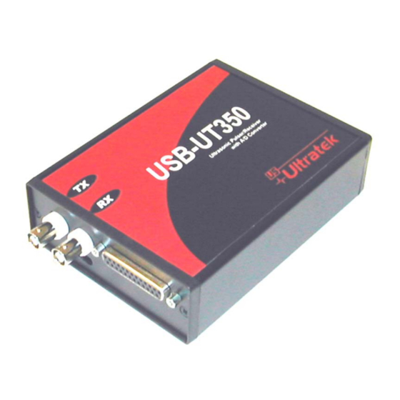
Doppler measurement, and flow meter. The following list shows the other products of this series: USB-UT350T is the tone burst version of the pulser/receiver. The letter T at the end of the part number stands for tone burst pulser. -
Page 5: Installation
2 Installation The supplied software should be installed prior to connecting the USB-UT350 to the computer. Software Installation Simply insert the disc labeled ‘USB-UT Software and Driver Disc’ and you will be presented with the following: Select next and follow the prompts to complete the installation. It is recommended that the default directory be used. -
Page 6: Hardware Connections
Hardware Connections 1. Connect the transducer(s) to the USB-UT 350. Select Single or Dual mode using the switch located beneath the BNC connectors for the old model. For the new model the single and dual mode can select using the scope software. 2. -
Page 7: Applications
3 Applications The USB-UT350 ultrasonic pulser/receiver and analog to digital converter can be used for a variety of applications. The device emits a negative high voltage pulse (or a series of tone burst pulses if the tone burst pulser is installed) on the TX connector and receives the response signal through either the TX connector or the RX connector depending on whether the device is in pulse/echo or through transmission mode. -
Page 8: Parameters
4 Parameters Pulse Power Pulse power ranges from -40V to -300V peak to peak in 256 steps. The response echoes are stronger when a higher voltage is used, however some transducers become saturated and require lower voltage settings. Pulse Width / Cycles For the Standard Pulser: The pulse width can be set to any value between 50ns and 500ns in increments of 20ns. -
Page 9: Dc Offset
DC Offset Sets the DC offset of the signal. Buffer Length The buffer length specifies how many samples the USB-UT350 will analyze during data acquisition. This value can be anywhere between 2 and 8191 samples, or 1 to 32000 with 32K memory option Trigger Delay The trigger delay specifies how many samples the A/D converter should skip before... -
Page 10: Trigger Type
4.11 Trigger Type There are three types of triggers available: Trigger Type +External External trigger on the rising edge. Software Internal software trigger. -External External trigger on the falling edge. 4.12 Sampling Rate The following sampling rates are supported by the USB-UT350: 50 MHz 25 MHz 12.5 MHz... -
Page 11: Tools
5 Tools Fast Fourier Transform (FFT) The oscilloscope software features the ability to transfer the waveform automatically to the QuickFFT software in order to display the Fourier transform of the signal. The original and transformed signals can be saved for later viewing or printed from within the QuickFFT software. -
Page 12: Hardware Configuration
6 Hardware Configuration DB-25 Connector The DB-25 connector provides the following signals: Input / Signal Description Output ENCA1 Encoder 1 (A) or Digital I/O Bit 8 ENCB1 Encoder 1 (B) or Digital I/O Bit 9 ENCA3 Encoder 3 (A) or Digital I/O Bit 12 ENCB3 Encoder 3 (B) or Digital I/O Bit 13 ENCA2... -
Page 13: Troubleshooting
7 Troubleshooting The USB-UT350 utilizes the full amount of current available as outlined in the USB 2.0 specification. The real world implementation of USB 2.0 varies between computers and some will provide more current to the device than others. If you are having difficulties maintaining a steady signal at high pulse voltages, make sure that there are no other devices drawing current from the USB. -
Page 14: Specifications
8 Specifications -40V to 300V p-p in 256 steps Pulse Voltage Pulse Width 50ns to 500ns in increments of 20ns 500Ω Damping Internal Trigger 1 Hz to 1,000 Hz in 1 Hz increments 0dB to 80dB in 0.1dB increments Receiver Gain Filter 0.6 MHz to 18 MHz fixed Full rectification, +Half rectification, -Half rectification, or RF...
Need help?
Do you have a question about the USB-UT350T and is the answer not in the manual?
Questions and answers