Table of Contents
Advertisement
Quick Links
ENGLISH
Read through the Installation Instructions before you proceed with the installation.
In particular, you will need to read under the "Safety Precautions" on page 2.
FRANÇAIS
Lisez les instructions d'installation avant de commencer l'installation.
En particulier, vous devez lire la section « Consignes de sécurité » en page 14.
ESPAÑOL
Lea las Instrucciones de instalacion antes de proceder con la instalacion del equipo.
En concreto, deberá leer detenidamente la sección "Precauciones de seguridad" situada en la página 26.
DEUTSCH
Lesen Sie die Einbauanleitung, bevor Sie mit der Installation beginnen.
Insbesondere müssen die „Sicherheitsvorkehrungen" auf Seite 38 gründlich durchgelesen werden.
ITALIANO
Leggere le Istruzioni di installazione prima di procedere con l'installazione.
Prestare particolare attenzione alla sezione "Precauzioni di Sicurezza" a pagina 50.
NEDERLANDS
Lees de installatie-instructies voordat u verder gaat met de installatie.
U moet in het bijzonder de "Veiligheidsvoorschriften" op pagina 62 lezen.
PORTUGUÊS
Leia cuidadosamente as instruções de instalação antes de prosseguir com a instalação.
Em particular, é necessário ler as informações na secção "Precauções de segurança" na página 74.
TÜRKÇE
Kuruluma başlamadan önce Kurulum Talimatlarını baştan sona okuyun.
Özellikle 86. sayfadaki "Güvenlik Önlemleri" kısmını okumanız gerekecektir.
POLSKI
Przed przystąpieniem do instalacji należy przeczytać instrukcje instalacyjne,
a w szczególności „Środki ostrożności" na stronie 98.
РУССКИЙ
Прежде чем приступать к установке, прочитайте инструкцию по установке.
В частности, следует прочитать раздел «Меры безопасности» на стр. 110.
УКРАЇНСЬКА
Перед початком установки уважно прочитайте інструкції.
Особливу увагу зверніть на розділ «Запобіжні заходи» на ст. 122.
Panasonic Corporation
1006 Kadoma, Kadoma City, Osaka, Japan
85464369966010
Panasonic Corporation
http://www.panasonic.com
Installation Instructions
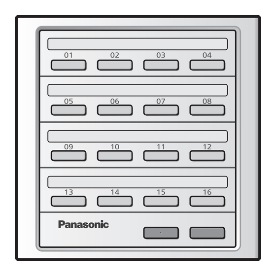
ON/OFF Controller
CZ-ANC3
Model No.
2-13
14-25
26-37
38-49
50-61
62-73
74-85
86-97
98-109
110-121
122-133
H0517-0
CV6233339986
E
NGLISH
F
RANÇAIS
E
SPAÑOL
D
EUTSCH
I
TALIANO
N
EDERLANDS
P
ORTUGUÊS
T
ÜRKÇE
P
OLSKI
Р
УССКИЙ
У
КРАЇНСЬКА
Advertisement
Table of Contents

Related Manuals for Panasonic CZ-ANC3


Summary of Contents for Panasonic CZ-ANC3
- Page 1 Installation Instructions ON/OFF Controller CZ-ANC3 Model No. 2-13 ENGLISH Read through the Installation Instructions before you proceed with the installation. NGLISH In particular, you will need to read under the “Safety Precautions” on page 2. 14-25 FRANÇAIS Lisez les instructions d'installation avant de commencer l'installation.
-
Page 2: Safety Precautions
ENGLISH Safety Precautions Please Read Before Starting This controller must be installed by the sales dealer or installer. These instructions are all you need for most installation sites and maintenance conditions. If you require help for a special problem, contact our sales/service outlet or your certifi... - Page 3 WARNING Provide a power outlet to be used exclusively for this controller. Turn off the circuit breaker of the controllers before installation. Do not supply power to the controller until all wiring is completed or reconnected and checked. ...
-
Page 4: Table Of Contents
Dimensions ........5 Test Operation ........ 12 Installation Precautions ....5 Central Address Setting ....13 Specifi cations Model No. CZ-ANC3 Dimensions (H) 120.5 mm x (W) 121.5 mm x (D) 14 + 51.1 mm Weight 500 g Temperature/ 0 ˚C to 40 ˚C / 20 % to 80 % (no condensation) -
Page 5: Dimensions
Dimensions ON/OFF Controller 121.5 51.1 2.0-R2.5 Swich box Installation Precautions Installation location Avoid the following locations for installation. • Under direct sunlight • Location near heat source • Uneven surface • Locations where the controller will be splashed with water or affected by dampness or humidity •... -
Page 6: Wiring
Wiring Before connecting wiring, be sure to turn the circuit breaker off. After all wiring arrangements are complete, turn the circuit breaker on. If the power supply wiring is mistakenly connected to a terminal board other than the power supply terminal board, the devices to be connected to this controller or this controller will malfunction. - Page 7 Basic wiring diagram Connect the inter-unit control wiring as shown in the fi gure. When connecting interface adaptor, read the installation instructions supplied with each product. Power Source ON/OFF Controller 100-240V ~ Outdoor Outdoor unit unit Inter-unit control wiring T1 T2 •...
- Page 8 Wiring (continued) Connecting wiring Remove the 2 screws for fi xing the cover, and remove the power source cover. Connect the power supply wiring to the power supply terminal board. Be sure to connect the earth wiring to the earth terminal. ...
- Page 9 Connecting to external equipment Keep the signal input line lengths to 100 meters or less. For distances greater than this, use a relay. External equipment ON/OFF controller side Input/Output side Name item Condition Terminal name Circuit example Output Non-voltage contact “a” Static (Relay output) Alarm output (DO 1)
-
Page 10: Mounting
Mounting When mounting the bottom case (step 2) Tighten the screws securely until they reach the bottom case. (Otherwise, loose screw heads may hit the PCB and cause malfunction when mounting the top case.) Do not over-tighten the screws. (The bottom case may be deformed, resulting in fall of the unit.) Embed the included switch box into the wall beforehand. -
Page 11: Switches
Switches * The factory defaults are as follows. OFF : SW1·2·3·4·8 ON : SW5·6·7 [SW1•2] Zone address setting Select a zone from Zone 1 to 4 based on the group (Central address) to operate. [SW3] ON/OFF controller Main/Sub setting (Main: OFF Sub: ON) ... -
Page 12: Test Operation
Test Operation (Preparation) Referring to the operating instructions for indoor units and outdoor units, perform the test operation beforehand. (1) Turn on this unit. (Button 16 of this unit blinks, and the indoor unit connection group is automatically checked.) (2) Press the “ALL ON” button of this unit, and confi rm the buttons (indicators) light up. (The buttons light up in the ascending order of the button number at one-second intervals.) Confi... -
Page 13: Central Address Setting
Central Address Setting * After the test operations for indoor units and outdoor units have fi nished, set the central address. This unit is not equipped with the central address setting function. If using the unit in combination with central control devices (system controller, intelligent controller, etc.) that can set the central address, set the central address using such devices. - Page 14 Authorized representative in EU Panasonic Testing Centre Panasonic Marketing Europe GmbH Winsbergring 15, 22525 Hamburg, Germany © Panasonic Corporation 2017 Printed in Japan...
Need help?
Do you have a question about the CZ-ANC3 and is the answer not in the manual?
Questions and answers