Table of Contents
Advertisement
Advertisement
Table of Contents

Related Manuals for Bpt TH 125


Summary of Contents for Bpt TH 125
- Page 1 THERMOPROGRAM PROGRAMMABLE THERMOSTAT TH 125 °C °C °C °C INSTRUCTIONS FOR USE TH125E 24806650 13-03-13...
- Page 2 Congratulations on the purchase of this TH125 WARNINGS thermostat. FOR THE INSTALLER For best performance and to enable the best use of this programmable thermostat’s characteristics and functions please read this manual carefully and • Read the warnings contained herein with care as keep it available for future reference.
- Page 3 THERMOPROGRAM DISPOSAL TH125 Do not litter the environment with packaging mate- rials: make sure it is disposed of according to the The TH125 THERMOPROGRAM programmable regulations in force in the country where the prod- uct is to be used. thermostat has been designed to guarantee ideal temperature conditions at all times during the day.
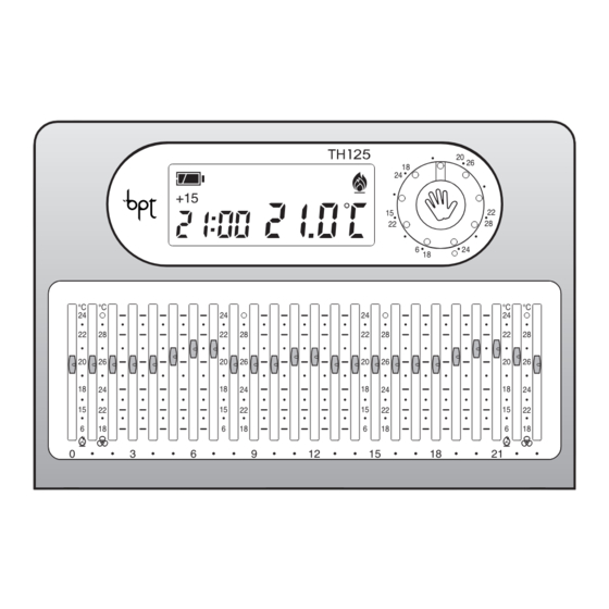
- Page 4 14 15 12 13 +15 +30 +45 °C °C °C °C Fig. 1...
- Page 5 SYMBOLS AND CONTROLS (fig. 1) MANUAL operating mode symbol. Door closing sensor button. Cooling operating mode symbol. Reset. Heating operating mode symbol. Display Programmed Digital thermometer. Temperature/Thermal Differential button. MANUAL or AUTOMATIC operating mode select button. Setting the clock and the start-up and shut-down delay period Manual temperature adjustment control...
- Page 6 Increment (temperature, day, hour, 24 6÷24°C Heating programme temperature etc.). range ( Decrement (temperature, day, hour, 25 18÷31°C Cooling programme temperature etc.). range ( ). A position higher than 21 6÷24°C Heating programme temperature 31°C (O) turns the system OFF. range ( ) in MANUAL operating mode.
-
Page 7: Table Of Contents
CONTENTS Chapter Page 1 - Position 13 - Displaying the programmed temperatures 2 - Installation 14 - Setting the system start-up 3 - Power supply and shut-down delay period 4 - Thermal differential 15 - Remote control 5 - Setting the clock 16 - Battery replacement 6 - Heating or cooling programme 17 - Thermostat fault condition... -
Page 8: Position
1 - POSITION 2 - INSTALLATION Install the unit on an internal wall (fig. 2) in a posi- Open the unit by pressing button P (fig. 3) while at tion which is suitable for correct room temperature the same time pulling in the direction of the arrows. measurement. - Page 9 Fig. 4 Fig. 5...
- Page 10 Fig. 6 Fig. 7...
-
Page 11: Electrical Connections
ATTENTION. For the unit to work properly, we rec- ommend that it should be mounted on a flat surface. Be careful not to tighten the screws excessively. ELECTRICAL CONNECTIONS The wiring will depend on the type of equipment to be controlled by the thermostat: refer to the dia- gram in fig. -
Page 12: Power Supply
Loads U1 = burner, circulation pump, solenoid valve, etc. U2 = motorised valve 3 - POWER SUPPLY Insert three new alkaline LR03 penlight AAA 1.5V batteries of the same type. Pay attention to polarity as shown on the bottom of the housing (fig. 10). ATTENTION. - Page 13 Fig. 10 Fig. 11...
-
Page 14: Thermal Differential
Fig. 12 Fig. 13 ATTENTION. Whenever the thermostat door is opened for making adjustments it is then neces- sary to close it correctly so as to avoid running the batteries down unnecessarily (fig. 60). 4 - THERMAL DIFFERENTIAL The thermal differential is adjustable from 0.1°C to 0.9°C. -
Page 15: Setting The Clock
Fig. 15 Fig. 16 5 - SETTING THE CLOCK 4.1 - Press the button twice (fig. 13). d 0.2°C 5.1 - Press button (fig. 15). appears on the display and remains there for 10 seconds. The minutes digits flash. 4.2 - Press the button (backwards) or (for- 5.2 - Press the... -
Page 16: Heating Or Cooling Programme
Fig. 17 Fig. 19 5.5 - Press button to end the procedure for set- ting the time (fig. 19). The colon between the hours and minutes flashes confirming that the the operation is complete. If no button is pressed for 10 seconds, the unit automatically exits this procedure, saving the last set data. -
Page 17: Automatic Operation
Fig. 20 Fig. 21 7 - AUTOMATIC OPERATION mode will be activated. In cooling programme mode the temperatures that can be selected are in the At initial switch-on the thermostat starts in AUTO- range 18°C to 31°C MATIC operating mode. Selecting a value above 31°C causes the system to If the thermostat is operating in MANUAL mode turn off. -
Page 18: Manual Operation
°C Fig. 22 Fig. 24 the temperatures, to avoid running the batter- ies down unnecessarily, close the door. 8 - MANUAL OPERATION 8.1 - Switch from AUTOMATIC to MANUAL mode by pressing the button (fig. 24) (the symbol on the dis- play reflects the selected mode). -
Page 19: Manual Timed Programme
Fig. 25 Fig. 26 9 - MANUAL TIMED PROGRAMME Programming by the hour 9.1 - Select MANUAL operating mode and set the If a fixed temperature is to be maintained for a few desired temperature using the rotary control (fig. 26). hours or a few days (for example, to maintain a 9.2 - Press button (fig. - Page 20 Fig. 27 Fig. 29 Programming by the day 9.4 - Select MANUAL operating mode and then set the desired temperature using the rotary control (fig. 30). 9.5 - Press the button twice (fig. 31). In place of the current time d01 will appear. 9.6 - Press the buttons (fig.
-
Page 21: System Bypass In Heating Mode
Fig. 30 Fig. 32 10 - SYSTEM BYPASS IN HEATING MODE System bypassing can be applied with or without frost protection. System bypass is useful during cleaning, maintenance work, or when absent, etc. The unit simply functions as a clock and room ther- mometer With frost protection Fig. - Page 22 Fig. 33 Fig. 34 The previously set frost temperature appears on the display. This value can be altered using the buttons (fig. 35). Any temperature can be chosen between 2°C and 35°C. The newly set temperature will be main- tained until further adjustments are made or until a different operating mode is selected.
-
Page 23: System Bypass In Cooling Mode
Fig. 36 Fig. 37 The OFF symbol confirms that THERMOPRO- For 5 seconds the room temperature reading dis- GRAM system control has been bypassed. appears to be replaced by For 5 seconds the room temperature reading dis- 11.2 - To go back to AUTOMATIC operation press appears to be replaced by button. - Page 24 Fig. 38 Fig. 39 Programming by the hour ming is performed. The remaining part of the hour 12.1 - Make sure that the system is operating in sys- when the operation is performed is therefore tem bypass mode (with or without frost protection). counted as one hour.
-
Page 25: Displaying The Programmed Temperatures
Fig. 40 Fig. 41 thermostat returns to AUTOMATIC operating 12.5 - Press the button twice (fig. 40). mode. In place of the current time d01 will appear. Note. To return to AUTOMATIC operating mode For 5 seconds the room temperature reading dis- before the programmed period expires press the appears to be replaced by or the frost pro-... - Page 26 Fig. 42 Fig. 43 For example if the clock displays 11.45 and the slider associated with that hour (C11) is positioned at 20°C, the display will reveal C11 20°C. 13.2 - Press the buttons (fig. 43) to see the temperatures associated with the other sliders (only when operating in automatic mode).
-
Page 27: Setting The System Start-Up And Shut-Down Delay Period
Fig. 45 Fig. 46 14 - SETTING THE SYSTEM START- 14.4 - Within 5 seconds press the button (fig. UP AND SHUT-DOWN DELAY PERIOD 46) and select a delay period of 15, 30 or 45 min- utes or else cancel the setting altogether. For exam- It is possible to delay system start-up and shut- down by 15, 30, or 45 minutes. -
Page 28: Remote Control
The delay can be programmed for several different hours during the same day. 15 - REMOTE CONTROL Connecting an appropriate interface to terminal block connections 1-2 (fig. 8 or 9) it is possible to remotely active a special pre-defined SHORT TERM MANUAL PROGRAMME. -
Page 29: Battery Replacement
Fig. 48 Fig. 50 from 1 to 99. 15.5- To save this programme such that it can be activated remotely press button 16 - BATTERY REPLACEMENT When the symbol flashes on the display, it means that there is around 1 month left to replace the batteries (fig. - Page 30 Fig. 51 Fig. 52 ATTENTION. Failure to replace the batteries in time may cause damage to the heating sys- tem (anti-freeze protection is not ensured). To replace the batteries, proceed as follows: 16.1 - Press button P on the base (fig. 55) and open the unit.
- Page 31 Fig. 54 be approximately 2 minutes available for replacing the batteries. If the batteries are not replaced with the available period or if the reset button R (fig. 54) is pressed all settings will be lost. To restart the unit, proceed as described in chapter 4.
- Page 32 Fig. 56 Fig. 57...
-
Page 33: Thermostat Fault Condition
ATTENTION. Every time the door is opened make sure that it is then closed correctly (fig. 60) so as to avoid running the batteries down unnecessarily. 17 - THERMOSTAT FAULT CONDITION In the event of an error condition press button R button (fig 54). - Page 34 Fig. 59 Fig. 60...
-
Page 35: Technical Characteristics
19 - TECHNICAL CHARACTERISTICS • Reading resolution: 0.1°C. • Displayed reading range: from 0°C to +40°C Unit for domestic use. • Precision: ≤ ±0.3°C. • Independently installed electronic device. • Class A software. • LCD display. • Degree of pollution: 2. •... - Page 36 BPT S.p.A. a Socio Unico Via Cornia, 1 33079 Sesto al Reghena-PN-Italy www.bpt.it-info@bpt.it...
Need help?
Do you have a question about the TH 125 and is the answer not in the manual?
Questions and answers