Table of Contents
Advertisement
Quick Links
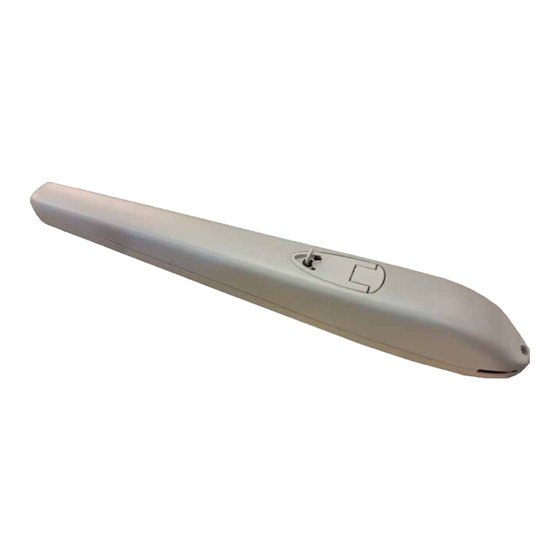
XTILUS
MOTORIDUTTORE IRREVERSIBILE PER CANCELLI A BATTENTE
IRREVERSIBLE GEARMOTOR FOR WING GATES
MOTORéDUCTEUR IRREVERSIBLE POUR PORTAILS à BATTANTS
MOTORREDUCTOR IRREVERSIBLE PARA CANCELAS A HOJAS
Motoriduttore
Gearmotor
Motoréducteur
Motorreductor
XTILUS
XTILUS 24V
Alimentazione
Larghezza max anta
Power Supply
Max wing width
Alimentation
Largeur max du battant
Alimentación
Longitud máx hoja
230V 50/60Hz
3,5 m
24Vdc
3,5 m
Peso max anta
Spinta max
Max wing weight
Max Thrust
Poids max du battant
Poussée maxi
Peso máx hoja
Max Empuje
400 Kg / 880 lbs
1600 N
350 Kg / 770 lbs
1600 N
Codice
Code
Code
Codigo
12007422
12007424
Advertisement
Table of Contents

Related Manuals for Allmatic XTILUS


Summary of Contents for Allmatic XTILUS
- Page 1 Motorreductor Alimentación Longitud máx hoja Peso máx hoja Max Empuje Codigo XTILUS 230V 50/60Hz 3,5 m 400 Kg / 880 lbs 1600 N 12007422 XTILUS 24V 24Vdc 3,5 m 350 Kg / 770 lbs 1600 N 12007424 MADE IN ITALY...
- Page 2 In any case, the IEC 364 standard and Installation regulations accidentale (ad esempio installandolo dentro quadro chiuso a chiave). 2° - Per la sezione ed il tipo dei cavi ALLMATIC consiglia di utilizzare un cavo di In force In your Country.
- Page 3 SYSTEM LAYOUT A - XTILUS gearmotor B - Control unit with box FIG. 1 C - Key selector D - Tuned antenna E - Flashing lamp F - Photocells (external) G - Photocells (internal) H - Column for photocells TECHNICAL FEATURES...
- Page 4 XTILUS INSTALLATION CHECKING BEFORE THE INSTALLATION Parts to install meeting the EN 12453 standard USE OF THE SHUTTER - THE GATE SHALL MOVE FRICTIONLESS - COMMAND TYPE Skilled persons Skilled persons Unrestricted use (out of public area*) (public area) Note: gate features must be uniformed with the standards and laws in force.
- Page 5 FIXING OF THE REAR PLATE TO THE COLUMN Front plate Rear plate Fix the rear plate to the column (Fig. 4) in accordance to the desired coordinates. In case an iron pillar is available, screw directly onto the column the plate with 3 screws M8..
- Page 6 TROUBLESHOOTING PROBLEM PROBABLE CAUSE SOLUTION 230 volt mains voltage absent. Check the main switch. Check for any STOP selectors or commands. Emergency STOP present. If not used, check the jumper on the STOP input of By giving a command with the remote control or the control unit.
- Page 7 MADE IN ITALY ALLMATIC S.r.l 32020 Lentiai - Belluno – Italy Via dell’Artigiano, n°1 – Z.A. Tel. 0437 751175 – 751163 r.a. Fax 0437 751065 www.remotecontrolgates.co.uk 01482 860950 6-1624846 rev.14 23/03/2016...
Need help?
Do you have a question about the XTILUS and is the answer not in the manual?
Questions and answers