
Subscribe to Our Youtube Channel
Related Manuals for GE MDS Mercury 900


Summary of Contents for GE MDS Mercury 900
- Page 1 MDS Mercury Series Wireless IP/Ethernet Transceiver Covering all AP and Remote Units including Mercury 900, 3650, and Option Set 1 Remotes 05-4446A01, Rev. E MARCH 2009...
-
Page 2: Table Of Contents
1.2 PRODUCT DESCRIPTION..................... 4 1.2.1 Model Offerings ........................6 1.2.2 Remote Radio with Option Set 1 ..................7 1.2.3 GE MDS P23 Protected Network (Redundant) Configuration ..........8 1.2.4 External GPS PPS Option ....................9 1.3 APPLICATIONS ......................9 1.3.1 Mobile/Fixed Data System ....................9 1.3.2 Wireless LAN ........................ - Page 3 2.4 STEP 3: CONNECT PC TO THE TRANSCEIVER ............25 2.5 STEP 4: REVIEW TRANSCEIVER CONFIGURATION ..........25 2.5.1 Getting Started ........................25 2.5.2 Procedure .......................... 25 2.5.3 Basic Configuration Defaults ..................... 25 2.6 STEP 5: CONNECT LAN OR SERIAL DATA EQUIPMENT.......... 26 2.6.1 Option Set 1 Connectors ....................
- Page 4 3.7.2 Wireless Security Menu ..................... 95 3.7.3 IEEE 802.1x Device Authentication ................... 97 3.7.4 Manage Certificates ......................99 3.8 REDUNDANCY CONFIGURATION (AP ONLY) ............102 3.9 GPS CONFIGURATION (REMOTE ONLY) ..............107 3.10 DEVICE INFORMATION MENU ................109 3.11 PERFORMANCE INFORMATION MENU..............110 3.12 MAINTENANCE/TOOLS MENU ................
- Page 5 We also became experts in wireless communication standards and system applications worldwide. The result of our efforts is that today, thousands of utilities around the world rely on GE MDS-based wireless networks to manage their most critical assets.
- Page 6 As your wireless needs change you can continue to expect more from GE MDS. We'll always put the performance of your network above all. Visit us at www.GEmds.com...
- Page 7 A power connector with screw-type retaining screws as supplied by GE MDS must be used. Do not disconnect equipment unless power has been switched off or the area is known to be non-hazardous.
- Page 8 These systems will reuse or recycle most of the materials found in this equipment in a sound way. Please contact GE MDS or your supplier for more information on the proper dis- posal of this equipment.
- Page 9 viii Mercury Reference Manual 05-4446A01, Rev. E...
-
Page 10: Product Overview & Applications
1.2 PRODUCT DESCRIPTION ........... 4 1.2.1 Model Offerings ..............6 1.2.2 Remote Radio with Option Set 1 ..........7 1.2.3 GE MDS P23 Protected Network (Redundant) Config..8 1.2.4 External GPS PPS Option ............. 9 1.3 APPLICATIONS ..............9 1.3.1 Mobile/Fixed Data System ............. - Page 11 Mercury Reference Manual 05-4446A01, Rev. E...
-
Page 12: About This Manual
1.1 ABOUT THIS MANUAL This Reference Manual is one of two publications provided for users of the Mercury Series transceiver system. It contains detailed product information, an overview of common applications, a screen-by-screen review of the menu system, technical specifications, suggested settings for various scenarios, and troubleshooting information. -
Page 13: Product Description
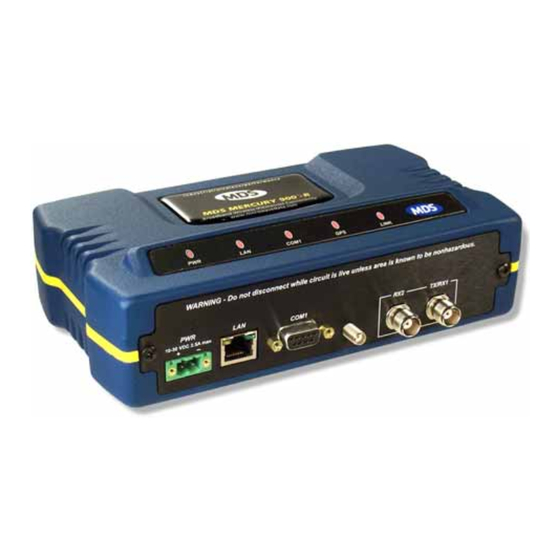
Mercury system the best combination of security, range, and speed of any industrial wireless solution on the market today. Invisible place holder Figure 1-1. The GE MDS Mercury Series Transceiver (Remote unit shown, AP similar in appearance) Rugged Packaging The transceivers are housed in a compact and rugged die cast-aluminum case that needs only protection from direct exposure to the weather. - Page 14 Security is not a one-step process that can simply be turned on and for- gotten. It must be practiced and enforced at multiple levels, 24 hours-a-day and 7 days-a-week. See “GE MDS CYBER SECURITY SUITE” on Page 17 for more information about the transceiver’s secu- rity tools.
-
Page 15: Model Offerings
• Built-in GPS Receiver—GPS technology is used for timing and location data. The only external equipment needed for this func- tionality is a GPS antenna available from GE MDS). 1.2.1 Model Offerings The transceiver comes in two primary models—Access Point and Remote. -
Page 16: Remote Radio With Option Set 1
Available Frequency Bands At the time of publication, Mercury transceivers are offered in two dif- ferent frequency bands: 902-928 MHz (Mercury 900) and 3.65–3.70 GHz (Mercury 3650). The 900 MHz unit operates in a license-free spec- trum (frequency hopping spread spectrum—FHSS), which may be used by anyone in the USA, provided FCC Part 15 rules are observed. -
Page 17: Ge Mds P23 Protected Network (Redundant) Configuration
The internal WiFi module has FCC modular approval and may only be operated by connecting one of the GE MDS approved antennas (see 802.11 WiFi Module Specifications below) to the reverse-SMA con- nector on the radio’s front panel. Only these antennas may be used. The WiFi module can operate as an 802.11 Access Point or Infrastructure... -
Page 18: External Gps Pps Option
protected chassis. For system-level information on this product, refer to MDS publication 05-4161A01. Invisible place holder Figure 1-3. MDS P23 Protected Network Station (incorporates two transceivers, with automatic switchover) 1.2.4 External GPS PPS Option The External GPS Precise Positioning Service (PPS) option allows for an external GPS device to provide the PPS input to the Mercury. -
Page 19: Wireless Lan
Invisible place holder Mercury Mercury AP remote Video Surveillance RTU/PLC (Ethernet) MDS NETview MS® Mercury Long Range WLAN remote RTU/PLC Computer Router RS-232 (Serial) MDS 4710 RTU/PLC RS-232 RS-232 (Serial) MDS 4790 Master Radio MDS 4710 Server (Ethernet) Licensed Serial/IP Integration Mercury Control Center Mercury... -
Page 20: Point-To-Point Lan Extension
IP format. A Remote transceiver with its serial port connected to a GE MDS serial-based radio, such as the MDS x790/x710, MDS TransNET and others, provides a path for bringing the data from the older radio into the IP/Ethernet environment of a Mercury-based system. -
Page 21: Wireless Lan With Mixed Services
to different SCADA hosts). A Mercury radio provides this capability using a single remote unit. The unit’s serial port can be connected via IP to different SCADA hosts, transporting different (or the same) proto- cols. Both data streams are completely independent, and the transceiver provides seamless simultaneous operation as shown in Figure 1-8. -
Page 22: Upgrading Older Wireless Network With Serial Interfaces
Millions of wireless data products have been installed in the last two decades for licensed and license-free operation, many of them manufac- tured by GE MDS. There are several ways that these systems can benefit from incorporating Mercury equipment. The chief advantages are inter- face flexibility (serial and Ethernet in one unit), and higher data throughput. -
Page 23: Network Design Considerations
NOTE: Several previous GE MDS-brand products had non-standard signal lines on their interface connectors (for example, to control sleep functions and alarm lines). These special func- tions are not provided nor supported by the Mercury trans- ceiver. Consult equipment manuals for complete pinout information. - Page 24 ration is sometimes required in a network that includes a distant Remote that would otherwise be unable to communicate directly with the Access Point station due to distance or terrain. The geographic location of a repeater station is especially important. Choose a site that allows good communication with both the Access Point and the outlying Remote site.
-
Page 25: Protected Network Operation Using Multiple Aps
Section 5.1.2, Site Selection (beginning on Page 164). 1.4.2 Protected Network Operation using Multiple Although GE MDS transceivers have a very robust design and have undergone intensive testing before being shipped, it is possible for iso- lated failures to occur. In mission-critical applications, down time can... -
Page 26: Ge Mds Cyber Security Suite
(See “A Word About Radio Interference” on Page 170 for more details.) 1.5 GE MDS CYBER SECURITY SUITE Today, the operation and management of an enterprise is increasingly dependent on electronic information flow. An accompanying concern becomes the cyber security of the communication infrastructure and the security of the data itself. - Page 27 Table 1-2. Security Risk Management Security Vulnerability GE MDS Cyber Security Solution Unauthorized access to the backbone • IEEE 802.1x device authentication network through a foreign remote radio •...
-
Page 28: Accessories
The transceiver can be used with one or more of the accessories listed in Table 1-3. Contact the factory for ordering details. Table 1-3. Accessories Accessory Description GE MDS Part No. AC Power A small power supply module designed for 01-3682A02 Adapter Kit continuous service. - Page 29 Table 1-3. Accessories (Continued) Accessory Description GE MDS Part No. DIN Rail Bracket used to mount the transceiver to 03-4022A03 Mounting standard 35 mm DIN rails commonly found in Bracket equipment cabinets and panels. COM1 Interface DB-25(F) to DB-9(M) shielded cable assembly...
-
Page 30: Tabletop Evaluation & Test Setup
TABLETOP EVALUATION AND TEST SETUP 2 Chapter Counter Reset Paragraph Contents 2.1 OVERVIEW ................23 2.2 STEP 1—CONNECT THE ANTENNA PORTS...... 23 2.3 STEP 2—CONNECT THE PRIMARY POWER ..... 24 2.4 STEP 3—CONNECT PC TO THE TRANSCEIVER....25 2.5 STEP 4—REVIEW TRANSCEIVER CONFIGURATION ..25 2.5.1 Getting Started ............... - Page 31 Mercury Reference Manual 05-4446A01, Rev. E...
-
Page 32: Overview
2.1 OVERVIEW GE MDS recommends that you set up a “tabletop network” to verify the basic operation of the transceivers. This allows experimenting with net- work designs, configurations, or network equipment in a convenient location. This test can be performed with any number of radios. -
Page 33: Step 2: Connect The Primary Power
(RSSI) at each transceiver during the test. In no case should a signal greater than –50 dBm be applied to any transceiver in the test setup. GE MDS recom- mends an RF power output level of +20 dBm from the AP. -
Page 34: Step 3: Connect Pc To The Transceiver
2.4 STEP 3: CONNECT PC TO THE TRANSCEIVER Connect a PC’s Ethernet port to the port using an Ethernet cross- over cable. The LED should light. Alternatively, you can use a COM1 serial cable to connect to the port (Figure 2-3 on Page 27). -
Page 35: Step 5: Connect Lan Or Serial Data Equipment
Table 2-1. Basic Configuration Defaults Item Menu Location Default Values/Range Main Menu>> Network Name MDS-Mercury • 1–15 alphanumeric Radio Configuration>> characters Network Name • Case-sensitive; can be mixed case Main Menu>> IP Address 192.168.1.1 Contact your network Network Configuration>> administrator IP Address Main Menu>>... - Page 36 Invisible place holder LED INDICATOR LAN PORT PANEL COM1 SERIAL PORT RX2 ANTENNA PORT DC POWER INPUT GPS ANTENNA TX/RX1 (10—30 VDC, 2.5A) CONNECTION ANTENNA PORT Figure 2-3. Transceiver Interface Connectors (Standard unit shown; See Figure 2-4 on Page 28 for Option Set 1 unit) LED INDICATOR PANEL •...
-
Page 37: Option Set 1 Connectors
2.6.1 Option Set 1 Connectors Figure 2-4 shows the interface connectors on the front panel of the Option Set 1 Remote transceiver. NOTE: The use of shielded Ethernet cable is recommended for connection to the radio’s port. The radio meets regulatory emission standards without shielded cable, but shielding reduces the possibility of interference in sensitive environ- ments, and is in keeping with good engineering practice. -
Page 38: Step 6: Check For Normal Operation
GPS ANTENNA PORT • — Coaxial connector (SMA-type) for connection of a GPS receiving antenna. Provides 3.5 Vdc output for compatibility with powered (active) GPS antennas. Do not short this connector, as you might cause damage to the internal power supply. The GPS receiving antenna’s gain must be 16 dBi or less. - Page 39 If the radio network seems to be operating properly based on observa- tion of the unit’s LEDs, use the command to verify the link integ- PING rity with the Access Point. Table 2-2. Transceiver LED Functions LED Label Activity Indication Primary power (DC) present Blinking Unit in “Alarmed”...
-
Page 40: Device Management
DEVICE MANAGEMENT 3 Chapter Counter Reset Paragraph Contents 3.1 INTRODUCTION ..............33 3.1.1 Differences in the User Interfaces ..........33 3.2 ACCESSING THE MENU SYSTEM ........35 3.2.1 Methods of Control ..............36 3.2.2 PC Connection and Log In Procedures ........36 3.2.3 Navigating the Menus .............. - Page 41 3.10 DEVICE INFORMATION MENU..........109 3.11 PERFORMANCE INFORMATION MENU ......110 3.12 MAINTENANCE/TOOLS MENU..........123 3.12.1 Installing Firmware via TFTP ..........129 3.12.2 Auto Firmware Upgrade Menu (AP Only) ......138 3.13 PERFORMANCE OPTIMIZATION ........140 3.13.1 Proper Operation What to Look For ........143 Mercury Reference Manual 05-4446A01, Rev.
-
Page 42: Introduction
Ethernet-based interfaces. Essentially, the same capabilities are avail- able through any of these paths. For support of SNMP software, a set of MIB files is available for down- load from the GE MDS Web site at www.GEmds.com . An overview of SNMP commands can be found at SNMP Agent Configuration section... - Page 43 Figure 3-1. Embedded Management System Top-Level Flowchart Mercury Reference Manual 05-4446A01, Rev. E...
-
Page 44: Accessing The Menu System
Figure 3-2. View of MS with a text-based program (Console Terminal shown Telnet has similar appearance) Invisible place holder Figure 3-3. View of the MS with a Browser (Selections at left provide links to the various menus) 3.2 ACCESSING THE MENU SYSTEM The radio has no external controls or adjustments. -
Page 45: Methods Of Control
3.2.1 Methods of Control Access the unit’s configuration menus in one of several ways: • Local Console—This is the primary method used for the exam- COM1 ples in this manual. Connect a PC directly to the port using a serial communications cable and launch a terminal com- munications program such as HyperTerminal (found on most PCs by selecting Start>>Programs>>Accessories>>Communica-... - Page 46 Invisible place holder Transceiver Transceiver To COM1 or LAN Port (See Text) T o COM1 or LAN Port (see text) PC Running T erminal Session PC Running Terminal Session (115,200 bps, 8N1) (115,200 bps, 8N1) Figure 3-4. PC Configuration Setup Starting a Local 1.
- Page 47 5. Enter your password (default password is admin ). For security, your password keystrokes do not appear on the screen. Press ENTER NOTE: Passwords are case sensitive. Do not use punctuation mark characters. You may use up to 13 alpha-numeric characters. The unit responds with the Starting Information Screen (Figure 3-6).
- Page 48 TIP: You can start a Telnet session on most PCs by selecting: Start>>Pro- . At the command prompt grams>>Accessories>>Command Prompt window, type the word telnet , followed by the unit’s IP address (e.g., ). Press to receive the Telnet log in telnet 10.1.1.168 ENTER screen.
-
Page 49: Navigating The Menus
Invisible place holder Figure 3-7. Log-in Screen when using a Web Browser NOTE: Passwords are case sensitive. Do not use punctuation mark characters. You may use up to 13 alpha-numeric characters. 5. Click . The unit responds with a startup menu screen similar to that shown in Figure 3-8. - Page 50 associated screen where settings may be viewed or changed. In most cases, pressing the ESCAPE key moves the screen back one level in the menu tree. In general, the top portion of menu screens show read-only information (with no user selection letter). The bottom portion of the screen contains parameters you can select for further information, alteration of values, or to navigate to other submenus.
-
Page 51: Basic Overview Of Operation
NOTE: In the menu descriptions that follow, parameter options/range, and any default values are displayed at the end of the text between square brackets. Note that the default setting is always shown after a semicolon: available settings or range; default setting 3.3 BASIC OVERVIEW OF OPERATION 3.3.1 Starting Information Screen Once you have logged into the Management System, the Starting Infor-... -
Page 52: Main Menu
• Alarmed —The unit has detected one or more alarms that have not been cleared. At Remote: • Scanning —The unit is looking for an Access Point beacon signal. • Ranging —Unit is adjusting power, timing, and frequency with an AP. •... - Page 53 Figure 3-10. Main Menu (AP) (AP menu shown, Remote similar; Differences noted in text below) Figure 3-11. Main Menu (MDS 3650 Remote Only) • Starting Information Screen —Select this item to return to the Start- ing Information screen described above. •...
-
Page 54: Configuring Network Parameters
• Security Configuration —Tools to configure the security services available with the transceiver’s environment. (See “SECURITY CONFIGURATION MENU” on Page • Redundancy Configuration —(AP Only) Allows setting of the cri- teria for switchover in the event of loss of associated Remotes or excessive packet receive errors. - Page 55 Figure 3-13. Network Configuration Menu (Option Set 1 radio) • Network Interface Config —Presents a menu where you can view or set various parameters (VLAN Status, IP Configuration, and DHCP Server Configuration). • Ethernet Port Config —Presents a menu for defining the status of the Ethernet port (enabled or disabled), port follows association, and Ethernet filtering configuration.
- Page 56 ceeds. The transceivers use UTC (Universal Time Coordinated) with a configurable time offset. [ NOTE: The Mercury gets time of day data from the GPS receiver if the receiver gets a satellite fix. Network Interface Configuration Submenu Invisible place holder Figure 3-14.
- Page 57 About Virtual LAN in A VLAN is essentially a limited broadcast domain, meaning that all Mercury members of a VLAN receive broadcast frames sent by members of the same VLAN but not frames sent by members of a different VLAN. For more information, refer to the IEEE 802.1Q standard.
- Page 58 • VLAN Status —Defines whether the radio handles Ethernet frames in “extended” 802.1Q mode or in “normal” mode in the Ethernet port. If configured with a trunk port, the Mercury passes all tagged traffic regardless of the VLAN ID. The Mer- cury only uses the Data VLAN ID parameter when the...
- Page 59 Management VLAN Invisible place holder Subnet Configuration Menu Figure 3-16. Management VLAN Subnet Configuration Menu NOTE: Changes to any of the following parameters while communi- cating over the network (LAN or over-the-air) might cause a loss of communication with the unit you are configuring. You must re-establish communication using the new IP address.
- Page 60 You can make a network of radios with the DHCP-provided IP address enabled or with DHCP services disabled. In this way, you can accom- modate locations for which a fixed IP address is desired. NOTE: There should be only one active DHCP server in a network. If more than one DHCP server exists, network devices might randomly get their IP address from different servers every time they request one.
- Page 61 Invisible place holder Figure 3-18. DHCP Server Configuration (Data) Menu • DHCP Server Status —Enable/Disable the response to DHCP requests to assign an IP address. [ Disabled/Enabled; Disabled • DHCP Netmask —IP netmask to be assigned along with the IP address in response to a DHCP request.
- Page 62 • IP Address Mode —Defines the source of this device’s IP address. Only static IP addressing mode is available when VLAN Status is enabled [ Static; Static • IP Address —The IPv4 local IP address. [ 192.168.1.1 • IP Netmask —The IPv4 local subnet mask.
- Page 63 • 802.11 SSID —Service Set Identifier, the name of the wireless LAN to which to connect. This is equivalent to Network Name in GE MDS terminology. • 802.11 Channel —(Applies only when 802.11 Mode is set to Access Point ) Sets the 802.11 channel the device will use.
- Page 64 Invisible place holder Figure 3-22. 802.11 Security Menu • 802.11 Privacy Mode —Determines which privacy mode is used. None, WEP; None • 802.11 Encryption —Determines the strength of the WEP encryp- tion. [ 64 Bit, 128 Bit; 128 Bit • —A user-entered combination of characters that WEP Passphrase is used to generate a WEP Key.
-
Page 65: Ethernet Port Configuration Menu
• TX Power —Transmit power of the WiFi radio. [ 18; 15 • NIC in Bridge —When enabled, the WiFi interface is added to the Network Interface Card bridge, allowing traffic to pass between the WiFi and the other interfaces (LAN and wireless). enabled, disabled;... - Page 66 • Eth Port Follows Association (Remote Only)—When enabled, the Ethernet port is disabled until the Remote associates. This allows a PC or laptop connected to the Remote to know when the wireless link is available. This feature helps middleware on the laptop in making connectivity decisions.
-
Page 67: Bridge Configuration
3.4.3 Bridge Configuration Invisible place holder Figure 3-26. Bridge Configuration Menu • —View/set the priority of the bridge in the span- Bridge Priority ning tree. [ 0-65535; 32769 • Bridge Hello Time —View/set spanning tree hello time. This parameter affects how often the bridge sends a spanning tree Bridge Protocol Data Unit (BPDU). - Page 68 • mercury_comm.mib — MIB definitions for objects and events common to the entire Mercury Series • mercury_ap.mib —MIB definitions for objects and events for an Access Point transceiver • mercury_rem.mib —Definitions for objects and events for a Remote radio • mercury_sec.mib —For security management of the radio system NOTE: SNMP management requires that the proper IP address,...
-
Page 69: Ap Location Push Config Menu
• V3 Authentication Password —Authentication password stored in flash memory. This is used when the Agent is managing pass- words locally (or initially for all cases on reboot). This is the SNMPv3 password used for Authentication (currently, only MD5 is supported). This string can contain up to 30 alpha-numeric characters. - Page 70 Invisible place holder Figure 3-28. AP Location Push Config Menu Invisible place holder Figure 3-29. AP Location Info Configuration Menu, TFTP Mode 05-4446A01, Rev. E Mercury Reference Manual...
- Page 71 Invisible place holder Figure 3-30. AP Location Info Configuration Menu, USB Mode (Option Set 1 Remote only) —A selection of methods for transferring files to and • File Media from the radio available on firmware version 3.0 radios. The options are: TFTP •...
- Page 72 Invisible place holder Figure 3-31. AP Location Text File AP Locations File Syntax and Guidelines The AP Locations file is used by the Remote radio to determine which Access Point to connect to when operating in Hopping w/ Hand-offs mode. The AP Locations file is a simple text file containing information about the location and configuration of all Access Points that the Remote can associate with.
-
Page 73: Sntp Server Configuration
MAC address of the A radio and the other statement provides the MAC address of the B radio. The statement only needs to be CHANNELS present if the channel selection feature is used at the Access Point to limit which channels are active. If all channels are used, you can leave out the CHANNELS statement. -
Page 74: Radio Configuration
Invisible place holder Figure 3-32. SNTP Server Entry (on Network Configuration Menu) When SNTP Server is selected (item H), the area to the right of the param- eter becomes active, allowing you to enter a valid SNTP server address. Press the Return key to make the address entry active. 3.5 RADIO CONFIGURATION There are two primary layers in the transceiver network—radio and data. - Page 75 Invisible place holder Figure 3-34. Radio Configuration Menu • Network Name —The user-defined name for the wireless network. Any 40 character string; MDS-Mercury • Transmit Power (AP Only)—Sets/displays RF power output level in dBm. This setting should reflect local regulatory limitations and losses in antenna transmission line.
- Page 76 Frequency Control Menu The items shown on this menu vary depending on the Frequency Mode Selection ( Single Channel Static Hopping Hopping w/Hand-offs ). Examples of all three screens are provided below, followed by a description of the menu items. Invisible place holder Figure 3-35.
- Page 77 Figure 3-37. Frequency Control Menu (900 MHz Remote, Hopping w/Hand-offs Freq. Mode) Invisible place holder Figure 3-38. Frequency Control Menu (Mercury 3650 model only) • Frequency (Mercury 3650 only)—Used to set/display the radio’s operating frequency. MDS 3650 radios do not employ fre- quency hopping, thus the entry here is a specific RF operating channel.
- Page 78 NOTE: Frequency Mode Static Hopping on Access Points requires TDD Sync Mode GPS Required. Channel/Frequency Allocations for Single Channel 900 MHz are shown in Table 3-1. The transceiver uses up to 14 channels (0-13) depending on the bandwidth used (1.75 MHz or 3.5 MHz).
- Page 79 • Single Frequency Channel —The RF frequency that the inte- grated radio will operate on when in single frequency (non-hopping) mode. [ 0 to 6 for 3.5-MHz, 0 to 13 for 1.75-MHz; 0 • Frame Duration —Defines the over-the-air media access con- trol framing.
- Page 80 transmits while another is receiving, which prevents AP-to-AP interference. Changing this parameter requires a radio reboot. Free Run, GPS Required; Free Run ] Note: Do not use the Prefer GPS setting. • Channel Selection (AP only)—Opens a submenu where you can specify channel usage.
- Page 81 Table 3-2. Remote Hand-Off Parameters Strict Strict Strict Signal and Signal, Dis- Distance Connection Signal Distance tance, and Bearing RSSI Applicable Applicable Applicable Threshold SNR Threshold Applicable Applicable Applicable Distance Applicable Applicable Threshold Blacklist Time Applicable Applicable Applicable Applicable NOTE: In Table 3-2 above, modes using the “Closest 3 APs”...
- Page 82 Max Scanning Time —The maximum time to try to connect to an AP before trying the next one in the AP Locations file. RSSI Threshold —The RSSI cutoff for Signal modes. When the RSSI drops below this value, the Remote disconnects and looks for a new AP. SNR Threshold —The SNR cutoff point for Signal...
- Page 83 • Max Modulation —Sets the highest modulation speed the trans- ceiver will use. BPSK, QPSK-1/2, QPSK-3/4, 16QAM-1/2, 16QAM-3/4, 64QAM-2/3; QAM16-3/4 • Cyclic Prefix (AP only)—Amount of additional information added to the over-the-air packets to mitigate the effects of chan- nel multipath. [ 1/4, 1/8, 1/16,1/32;...
- Page 84 Modulation Table 3-3 on Page 75 shows the relationship between the radio’s Protec- Protection and tion Margin, Hysteresis Margin, and the SNR range allowed for each Hysteresis Margins form of modulation. Column A lists the available modulation types for the radio, while col- umns B and C show the minimum SNR range required to operate in each modulation.
-
Page 85: Serial Port Configuration
3.5.2 Serial Port Configuration Overview The transceiver includes an embedded serial device server that provides transparent encapsulation over IP. In this capacity, it acts as a gateway between serial and IP devices. Two common scenarios are PC applica- tions using IP to talk to remote devices, and serial PC applications talking to remote serial devices over an IP network. - Page 86 Data buffering is always active regardless of the selected mode. If you connect EIA-232 serial devices to the transceiver, review these parame- ters carefully. Serial Configuration Wizard GE MDS recommends the Serial Configuration Wizard, available through the Serial Port Configuration Menu , for configuration of the serial terminal services.
- Page 87 Serial Port Invisible place holder Configuration Menu Figure 3-41. Serial Port Configuration Menu Figure 3-42. Serial Configuration Wizard • Begin Wizard —Tool for configuring serial ports using a step-by-step process. • View Current Settings —Displays all setable options. Varies depending on the selected IP protocol. Mercury Reference Manual 05-4446A01, Rev.
- Page 88 Configuring for UDP Invisible place holder Point-to-Multipoint Figure 3-43. UDP Point-to-Multipoint Menu Use UDP point-to-multipoint to send a copy of the same packet to mul- tiple destinations, such as in a polling protocol. • Status —Enable/Disable the serial data port. •...
- Page 89 • Commit Changes and Exit Wizard —Save and execute changes made on this screen (shown only after changes have been entered). Invisible place holder Figure 3-44. UDP Point-to-Point Menu Configuring for UDP Use UDP point-to-point configuration to send information to a single Point-to-Point device.
- Page 90 • Buffer Size —Maximum amount of characters that the Remote end buffers locally before transmitting data through the serial port. [ 1—255; 255 • Inter-Packet Delay —Amount of time that signal the end of a message, measured in tenths of a second. [ default = 1 (that is, 1/10th of a second) •...
- Page 91 • Inter-Frame Packet Delay —A measurement representing the end of a message, measured in tenths of a second. default = 1 (that is, 1/10th of a second) • Commit Changes and Exit Wizard —Save and execute changes made on this screen (shown only after changes have been entered).
- Page 92 IP-to-Serial Application Example You must choose UDP or TCP to establish communications. This depends on the type of device you are communicating with at the other end of the IP network. In this example, we will use TCP to illustrate its use.
- Page 93 packet, the Remote strips the data out of the UDP packet and sends it out port. Likewise, data presented at the Remote’s port is packetized, sent to the Access Point, stripped, and sent out the Access Point’s port. This configuration does not use multicast addressing. Invisible place holder 192.168.0.10 192.168.0.1...
- Page 94 Invisible place holder 192.168.0.2 192.168.0.10 192.168.0.1 EIA-232 Remote 192.168.0.3 EIA-232 EIA-232 Access Point Terminal Remote or Computer EIA-232 192.168.0.4 Remote Figure 3-49. Point-to-Multipoint Serial-to-Serial Application Diagram Invisible place holder Table 3-6. Serial Port Application Configuration Transceiver Location Menu Item Setting Access Point (COM1) Status Enabled...
- Page 95 Figure 3-50. Serial Port Configuration Access Point Figure 3-51. Radio Serial Port Configuration Remote Mixed Modes In this example, the TCP mode does not involve the Access Point. Thus, the transceiver in a single network can run in both modes at the same time.
- Page 96 Operation and Data • Communicate with RTU A by Telneting to Remote 1, port 30010. Flow • Communicate with RTU B by Telneting to Remote 2, port 30010. • Communicate with RTUs C and D by sending and receiving data from the Access Point’s port.
-
Page 97: Modbus / Tcp Server Configuration
Table 3-7. Serial Port Application Configuration (Continued) Transceiver Location Menu Item Setting Send to Address IP address of the AP Send to Port 30010 Receive on Port 30010 Receive on Address 224.254.1.1 (The multicast IP address used for the AP’s Send To Address above) 3.6 MODBUS / TCP SERVER CONFIGURATION... -
Page 98: Menu Selections
3.6.2 Menu Selections Connect a PC to the transceiver as described in STEP 3: CONNECT PC TO THE TRANSCEIVER section on Page 25, and access the embedded management system. Follow the steps below to proceed with Modbus/TCP configuration. 1. From the Serial Configuration Wizard opening screen (Figure 3-53 on Page 89), select... - Page 99 Figure 3-55. Modbus/TCP Server Listening Port 4. On the next screen (Figure 3-56), press to change the Modbus serial format, then press the space bar to toggle between the avail- MODBUS/RTU MODBUS/ASCII able formats ( ). Press to enter the Modbus serial timeout value in milliseconds.
- Page 100 5. When the next screen appears (Figure 3-57), press to select the desired data baud rate and to select the data byte format. Press continue. Figure 3-57. Select Data Baud Rate and Byte Format 6. The screen shown in Figure 3-58 appears next.
-
Page 101: Security Configuration Menu
Invisible place holder Figure 3-59. Serial Port Status Screen 8. Review all settings on the summary screen shown in Figure 3-60. If all settings are correct, press to confirm and exit the wizard. If not, select the letter of the item(s) you wish to change. Invisible place holder Figure 3-60. -
Page 102: Device Security Menu
Wireless Security —Controls how and when radios communicate with each other, as well as how data traffic is handled. RADIUS Configuration —Deals with IEEE 802.1x device authentication and authorization using a central server. Manage Certificates (Remote only) —Allows setting of certificate types, download paths, and TFTP parameters. - Page 103 Invisible place holder Figure 3-62. Device Security Menu • Telnet Access —Controls Telnet access to the transceiver’s man- agement system. [ enabled, disabled; enabled • SSH Access —Controls access to the Secure Shell (SSH) server. enabled, disabled; enabled • HTTP Mode —Controls access to the transceiver’s management system via the web server.
-
Page 104: Wireless Security Menu
User Passwords Menu Invisible place holder Figure 3-63. User Passwords Menu To change the Administrator or Guest password, select the appropriate menu item (A or B). A flashing cursor appears to the right. From here, type the new password, which can be any alpha-numeric string up to 13 characters long. - Page 105 Invisible place holder Figure 3-64. Wireless Security Menu • Device Auth Mode —View/set the device’s authentication method. None, Local, IEEE 802.1X; None • Data Encryption —Controls the over-the-air payload data’s AES-128 bit encryption. [ enable, disable; disabled • —View/set the phrase used to generate encryp- Encryption Phrase tion keys when encrypting over-the-air payload.
-
Page 106: Ieee 802.1X Device Authentication
3.7.3 IEEE 802.1x Device Authentication This section covers the configuration needed for the radios to access the IEEE 802.1x device authentication server, which provides Device Level Security and for Wireless Access Security. GE MDS does not provide the server software. Operation of Device Authentication Device authentication forces the radio to authenticate before allowing user traffic to traverse the wireless network. - Page 107 Each Access Point and Remote radio must be identified/recognized by the device authentication server through the Common Name (Serial number) and IP address entries. NOTE: Consult your network administrator for assistance in configu- ration, or for help with other issues that may arise. To activate device authentication, select Device Auth Method and set...
-
Page 108: Manage Certificates
RADIUS Configuration Menu Invisible place holder Figure 3-66. Radius Configuration Menu • Auth Server Address —The IP address of the authentication server. [ any valid IP address; 0.0.0.0 • Auth Server Port —The UDP Port of the authentication server. 1812, 1645, 1812 •... - Page 109 Invisible place holder Figure 3-67. Manage Certificates Menu Invisible place holder Figure 3-68. Manage Certificates Menu, TFTP Mode (Option Set Remote only) Mercury Reference Manual 05-4446A01, Rev. E...
- Page 110 Invisible place holder Figure 3-69. Manage Certificates Menu, USB Mode (Option Set Remote only) —A selection of methods for transferring files to and • File Media from the radio. On firmware version 3.0 radios, the options are TFTP • TFTP Host Address —...
-
Page 111: Redundancy Configuration (Ap Only)
Invisible place holder Figure 3-70. Transfer Options Menu • TFTP Timeout —The time the client radio will wait for a response from the server before ending the transfer. • TFTP Block Size —The amount of data sent in each TFTP packet. 3.8 REDUNDANCY CONFIGURATION (AP ONLY) For operation in protected (redundant) mode, an AP must be in a Pack-... - Page 112 Invisible place holder Figure 3-71. Redundancy Configuration Menu (AP Only) • Redundancy Configuration —Enable/disable redundancy switcho- ver for AP. [ enabled, disabled; disabled • Network Event Triggers —This selection opens a submenu (Figure 3-72 on Page 104) where you can set/view the trigger status for Network Events.
- Page 113 Network Event Triggers Menu Invisible place holder Figure 3-72. Network Events Triggers Menu • Network Interface Error —This setting determines whether or not a network interface error will cause redundancy switchover. enabled, disabled; disabled Radio Event Triggers Invisible place holder Figure 3-73.
- Page 114 Hardware Event Triggers Invisible place holder Figure 3-74. Hardware Event Triggers • Init/Hardware Error —This setting determines whether or not an initialization or hardware error results in a redundancy switcho- ver. [ enabled, disabled; disabled Redundancy Configuration Options Menu Use this menu (Figure 3-75) to set the thresholds for the Lack of Asso- ciated Remotes and Packet Receive Errors.
- Page 115 • Packet Receive Errors Exceeded Threshold —This selection opens a submenu (Figure 3-77 on Page 106) where you can view or change the maximum allowable number of receive errors. Lack of Associated Invisible place holder Remotes Exceeded Threshold Menu Figure 3-76. Lack of Associated Remotes Exceeded Threshold Menu •...
-
Page 116: Gps Configuration (Remote Only)
This menu allows you to view or set important parameters for the built-in Global Positioning System (GPS) receiver in the Mercury Remote. Mercury 3650 Remote units do not have or require GPS func- tionality. Details about the NMEA sentences generated by the GE MDS Mercury can be found at http://www.nps.gov/gis/gps/NMEA_sentences.html Invisible place holder Figure 3-78. - Page 117 Invisible place holder Figure 3-79. GPS Streaming Configuration Menu • GGA Polling —Seconds between GGA string outputs, the satellite fix information. • GLL Polling —Seconds between GLL string outputs, the latitude and longitude information. • —Seconds between GSA string outputs, the overall GSA Polling satellite data.
-
Page 118: Device Information Menu
3.10 DEVICE INFORMATION MENU Figure 3-80 shows the menu that displays basic administrative data on the unit to which you are connected. It also provides access to user-spe- cific parameters such as date/time settings and device names. Figure 3-80. Device Information Menu •... -
Page 119: Performance Information Menu
• UTC Time Offset —Set/view the number of hours difference between your local clock time and Universal Coordinated Time. Offsets for U.S. times zones are shown in the chart below. Time Zone UTC Offset (U.S.) (Hours) • Device Names —Fields used at user’s discretion for general administrative purposes. - Page 120 important troubleshooting tool, or for evaluating changes made to the network configuration or equipment. Invisible place holder Figure 3-82. Performance Information Menu • Event Log —Access this menu for managing the unit’s opera- tional activities log. (See Figure 3-85 on Page 113 for details.) •...
- Page 121 Invisible place holder Figure 3-83. Performance Trend Screen Invisible place holder Figure 3-84. Bridge Status Menu Mercury Reference Manual 05-4446A01, Rev. E...
- Page 122 Event Log Menu Invisible place holder Figure 3-85. Event Log Menu • —Shows active alarms (if any) reported by the Current Alarms transceiver. • View Event Log —Displays a log of radio events arranged by event number, date, and time. (Example shown in Figure 3-86 on Page 114).
- Page 123 View Event Log Invisible place holder Menu Figure 3-86. View Event Log Menu The transceiver’s microprocessor monitors many operational parame- ters and logs them. Events are classified into four levels of importance, which are described in Table 3-8. Some of these events result from a condition that prevents normal operation of the unit.
- Page 124 Invisible place holder Figure 3-87. Packet Statistics Menu • Packets Received —Data packets received by this unit. • Packets Sent —Data packets sent by this unit. • Bytes Received —Data bytes received by this unit. • —Data bytes sent by this unit. Bytes Sent •...
- Page 125 GPS Status Menu Invisible place holder Figure 3-88. GPS Status Menu • GPS Serial Number —The serial number of the GPS unit in the radio. • GPS Firmware Version —The firmware version running on the GPS chip. • Satellite Fix Status —Indicates whether or not the unit has achieved signal lock with the minimum required number of GPS satellites.
- Page 126 GPS Information Invisible place holder Menu Figure 3-89. GPS Information Menu Wireless Network Status Menu The Wireless Network Status screen provides information on a key operating process of the transceiver—the association of the Remote with the Access Point. The following is a description of how this process takes place and is monitored by the menu system.
- Page 127 Invisible place holder Figure 3-90. Wireless Network Status Menu (AP) Invisible place holder Figure 3-91. Wireless Network Status Menu (Remote) • Device Status —Displays the overall operating condition of the transceiver. [ Operational, Alarmed • Associated Remotes (AP Only)—Shows the number of Remote transceivers currently associated with the AP.
- Page 128 • Connection Status (Remote Only)—Displays the current state of the wireless network communication as follows: Scanning, Rang- ing, Connecting, Authenticating, Associated, Alarmed . A complete explanation of these operating states is provided in Table 4-3 on Page 152. • Current AP Eth Address —Displays the Ethernet MAC address of the current AP.
- Page 129 Invisible place holder Figure 3-94. Remote Database Details Menu (AP) Internal Radio Status Menu (Remote Only) Invisible place holder Figure 3-95. Internal Radio Status (Remote Only) Mercury Reference Manual 05-4446A01, Rev. E...
- Page 130 Invisible place holder Figure 3-96. Internal Status Menu (Remote in Static Hopping mode) Invisible place holder Figure 3-97. Internal Radio Status Menu (Remote in Hopping with Handoffs Mode) NOTE: In the menu above, the items in the right hand column are displayed on Remotes only, when they are in Hopping with Handoffs mode.
- Page 131 • Transmit Power —Shows the RF power output from the transmit- ter. The AP changes the transmit power of the Remote to match the desired receive power at the APs receiver. This provides end-to-end power control. • Average RSSI —Shows average received signal strength indica- tion (RSSI) of incoming RF signals, displayed in dBm.
-
Page 132: Maintenance/Tools Menu
• RX Frequency Offset —This is a measurement of how far in fre- quency the Remote’s receiver has shifted (in Hz) to accommo- date the incoming signal from the AP. • Total FEC Count —This parameter shows the total number of For- ward Error Correction (FEC) blocks handled by the radio. - Page 133 Invisible place holder Figure 3-100. Maintenance/Tools Menu (AP) Invisible place holder Figure 3-101. Maintenance/Tools Menu (Remote) (Some versions may show a Scheduled Reboot option, described below) • Reprogramming —Managing and selecting the unit’s operating system firmware resources. (See “Reprogramming Menu” Page 126 •...
- Page 134 • Radio Test —A diagnostic tool for testing RF operation. (See “Radio Test Menu” on Page 138) • Firmware Versions —Shows the firmware code versions stored in the radio and indicates which one is the active image. (See Figure 3-102 on Page 125.) •...
- Page 135 Reprogramming Menu The factory sometimes offers upgrades to the transceiver firmware. Loading new firmware into the unit will not alter any privileges pro- vided by Authorization Keys and does not require you to take the trans- ceiver off-line until you want to operate the unit with the newly installed firmware image.
- Page 136 Invisible place holder Figure 3-105. Reprogramming Menu (Option Set 1 Remote only) Invisible place holder Figure 3-106. Reprogramming Menu (Option Set 1 Remote only) —A selection of methods for transferring files to and • File Media from the radio. On firmware version 3.0 radios, the options are TFTP •...
- Page 137 • Retrieve File —Initiates the file transfer from the TFTP server. The new file is placed into inactive firmware image. [ Y, N • Image Verify —Initiate the verification of the integrity of firm- ware file held in unit. • Image Copy —Initiate the copying of the active firmware into the inactive image.
-
Page 138: Installing Firmware Via Tftp
Starting Information Screen (See “Starting Information Screen” on Page 42.) A TFTP server is available on the GE MDS Web site at: www.GEmds.com/Resources/TechnicalSupport/ TIP: If you do not know your computer’s address on a Windows PC, you can use the... - Page 139 Invisible place holder REMOTE PC W/FIRMWARE FILES HUB/LAN/WAN/MAN TFTP SERVER TCP/IP TRANSCEIVER ETHERNET IP ADDRESS: 172.0.0.B PORT IP ADDRESS: 172.0.0.A PORT LOCAL WINDOWS PC COM1 COM1, 2, ETC. PORT (DTE) (DCE) INITIATE UPLOAD FROM HERE IP ADDRESS: w.x.y.z Figure 3-109. Firmware Upgrade Setup Option 2 (TFTP Server and Firmware File on Remote Server) NOTE: The COM1...
- Page 140 5. Download the firmware file from the TFTP server into the trans- ceiver. (Main Menu>>Maintenance Menu>>Reprogramming Menu>>Retrieve File) Status messages on the transfer are posted on the Management Sys- tem screen. NOTE: The new firmware image file that replaces the “Inactive Image”...
- Page 141 • To save “known-good” configuration files from your radios. These can be used for later restoration if a configuration prob- lem occurs, and it is unclear what parameter is causing the issue. • To facilitate the rapid configuration of a large number of radios. •...
- Page 142 Invisible place holder Figure 3-111. Configuration Scripts Menu (Option Set 1 Remote only) Invisible place holder Figure 3-112. Configuration Scripts Menu (Option Set 1 Remote only) —A selection of methods for transferring files to and • File Media from the radio. On firmware version 3.0 radios, the options are TFTP •...
- Page 143 Modify the configura- tion files using a text editor or an automated process. (These applica- tions are not provided by GE MDS). We recommend that you review and update the following parameters for each individual unit.
- Page 144 Table 3-10. Common User-Alterable Parameters (Continued) Field Comment Range Device Name Should reflect a specific device. Any 20-character alphanumeric string This information will appear in Management System headings. Location Used only as reference for network Any 40-character administration. alphanumeric string Editing Rules •...
- Page 145 • Ping —Send Ping packets to address shown on screen. This screen is replaced with a detailed report of Ping activity (see example in Figure 3-114). Press any key after viewing the results to return to this menu. Invisible place holder Figure 3-114.
- Page 146 Reset to Factory Defaults Use the Reset to Factory Defaults selection on the Maintenance/Tools Menu to return all configurable settings to those set at the factory prior to shipping. Use this selection with caution, as you will lose any custom settings you have established for your transceiver, and will need to re-enter them using the menu system.
-
Page 147: Auto Firmware Upgrade Menu (Ap Only)
3.12.2 Auto Firmware Upgrade Menu (AP Only) Invisible place holder Figure 3-117.Auto Firmware Upgrade Menu • Firmware Upgrade —Causes all of the Remotes associated to this AP to read the AP’s specified (by Firmware for Upgrade ) firmware version (active or inactive), and download it via TFTP to the inactive image if the Remote does not already have that firm- ware version. - Page 148 Invisible place holder Figure 3-118. Radio Test Menu NOTE : Using Test Mode disrupts traffic through the radio. If the unit is an Access Point, it will disrupt traffic through the entire network. The Test Mode function is automatically limited to 10 minutes.
-
Page 149: Performance Optimization
Spectrum Analyzer Menu (Remote Only) Using this menu, you can enable or disable the remote’s spectrum ana- lyzer mode (Figure 3-119 on Page 140). When enabled, the remote dis- plays through the terminal a spectrum analyzer view of its transmit power and frequency (Figure 3-120 on Page 140). - Page 150 There are two major areas for possible improvement—the radio and the data network. These sections provide a variety of items to check in both categories, and in many cases, ways to improve performance. NOTE: Antennas are one of the most important portions of the wire- less system.
- Page 151 Table 3-11. Recommended Settings for Common Scenarios For Fixed Locations, where best combination of range and throughput is desired. Remote Units Notes Network User User AP and Remote must match. Name discretion discretion Transmit Power In most cases, power can be set to this level (AP)/ (3650 model: 23) (3650 model: 23)
-
Page 152: Proper Operation And What To Look For
For Optimal Sensitivity (Trades off throughput for best possible sensitivity. AP more susceptible to interference) Remote Units Notes Radio Receive Sets AP receiver for highest gain. Configuration Power When Heavy Interference Exists at AP (Trades off range for robustness in the face of interference) Remote Units Notes... -
Page 153: Additional Considerations For Mobile Operation
Table 3-12. Mercury Remote Transceiver (Continued) (Performance Information>>Internal Radio Status Menu) Name Target Value Notes Strong signal (bench A low SNR may be caused by (Signal-to-Noise Ratio) setting): 25-28 dB noise or interfering signals. Operational: 3-30 dB Typ. System: 10-20 dB TX Freq. - Page 154 • Use connectionware—The use of connectionware in the mobile lap- tops is highly recommended for better operation of a mobile data system. GE MDS provides connectionware from one of the vendors in this market. Contact your factory representative for details.
- Page 155 Mercury Reference Manual 05-4446A01, Rev. E...
-
Page 156: Troubleshooting & Radio Measurements
TROUBLESHOOTING & RADIO MEASUREMENTS 4 Chapter Counter Reset Paragraph Contents 4.1 TROUBLESHOOTING............. 149 4.1.1 Interpreting the Front Panel LEDs ........... 149 4.1.2 Troubleshooting With the Embedded Management System ..150 4.1.3 Using Logged Operation Events ..........153 4.1.4 Alarm Conditions ..............154 4.1.5 Correcting Alarm Conditions ............ - Page 157 Mercury Reference Manual 05-4446A01, Rev. E...
-
Page 158: Troubleshooting
Factory Assistance If problems cannot be resolved using the guidance provided here, review the GE MDS web site’s technical support area for recent soft- ware/firmware updates, general troubleshooting help, and service infor- mation. Additional help is available through our Technical Support Department. -
Page 159: Troubleshooting With The Embedded Management System
resolving common system difficulties using the LEDs, and Table 4-2 on Page 151 provides other simple techniques. Table 4-1. Troubleshooting Using LEDs—Symptom-Based Symptom Problem/Recommended System Checks PWR LED does not a. Voltage too low—Check for the proper supply voltage at turn on the power connector. - Page 160 Table 4-2. Basic Troubleshooting Using the Management System Symptom Problem/Recommended System Checks Cannot access the a. Connect to unit via Telnet or Web browser. MS through COM1 b. Disable the serial mode for COM1 (Serial Gateway Configuration>>Com1 Serial Data Port>>Status>>Disabled). Or, if you know the unit’s data configuration: a.
- Page 161 connect to the Management System, see “STEP 3: CONNECT PC TO THE TRANSCEIVER” on Page Starting Information Screen (See Starting Information Screen on Page The Management System’s home page provides some valuable bits of data. One of the most important is the Device Status field.
-
Page 162: Using Logged Operation Events
Packet Statistics Menu (See Packet Statistics Menu on Page 114) This screen provides detailed information on data exchanges between the unit being viewed and the network through the wireless and the Ethernet (data) layers. These include: Wireless Packet Statistics • Packets received •... -
Page 163: Alarm Conditions
permanent memory (Flash memory) until cleared by user request. Table 4-4 summarizes these classifications. Table 4-4. Event Classifications Level Description/Impact Storage Alarms Transceiver has detected one or Flash more alarm conditions Memory Informational Normal operating activities Flash Memory Temporary Transient conditions or events Informational Minor Does not affect unit operation... -
Page 164: Correcting Alarm Conditions
Table 4-5. Alarm Conditions (Alphabetical Order) (Continued) Alarm Condition Reported Event Log Entry SNMP Trap EVENT_RSSI_CAL RSSI Not Calibrated rssiCal(9) EVENT_SYSTEM_ERROR* System Error Cleared; systemError(16) Please Reboot EVENT_TFTP_CONN TFTP connectivity tftpConnection(73) achieved EVENT_TFTP_ERR Attempted TFTP tftpConnFailed(79) connection failed * User can correct condition, clearing the alarm. 4.1.5 Correcting Alarm Conditions (See Event Log Menu on Page... - Page 165 The left hand column, Event Log Entry, is what shows in the Event Log. (See also Event Log Menu on Page 113.) Table 4-7. Non-Critical Events—Alphabetical Order Event Log Entry Severity Description Association Attempt MAJOR Self explanatory Success/Failed Association Lost - Local IP MAJOR Self explanatory Address Changed...
-
Page 166: Radio (Rf) Measurements
Table 4-7. Non-Critical Events—Alphabetical Order (Continued) Event Log Entry Severity Description System Bootup (power on) INFORM Self explanatory Telnet Access Locked for MAJOR Self explanatory 5 Min Telnet User Logged MAJOR Self explanatory Out/Logged In User Selected Reboot MAJOR Self explanatory 4.2 RADIO (RF) MEASUREMENTS There are several measurements that should be performed during the ini- tial installation. -
Page 167: Antenna Aiming (For Directional Antennas)
Procedure 1. Place a directional wattmeter between the antenna connector and the antenna system. 2. Place the transceiver into the Radio Test Mode using the menu sequence below: (Maintenance/Tools Menu>>Radio Test>>Radio Mode>>Test) 3. Set the transmit power to 29 dBm (900 model), or 23 dBm (3650 model). - Page 168 RSSI measurements and Wireless Packet Statistics are based on mul- tiple samples over a period of several seconds. The average of these measurements is displayed by the Management System. The measurement and antenna alignment process usually takes 10 or more minutes at each radio unit. The path to the Management System menu item is shown in bold text below each step of the procedure.
- Page 169 7. If the RSSI peak results in an increase in the Wireless Packets Dropped and Received Error, the antenna may be aimed at an undes- ired signal source. Try a different antenna orientation. End of procedure. Mercury Reference Manual 05-4446A01, Rev. E...
-
Page 170: Planning A Radio Network
PLANNING A RADIO NETWORK 5 Chapter Counter Reset Paragraph Contents 5.1 INSTALLATION PLANNING163 5.1.1 General Requirements 163 5.1.2 Site Selection 164 5.1.3 Terrain and Signal Strength 165 5.1.4 Antenna & Feedline Selection 165 5.1.5 How Much Output Power Can be Used? 169 5.1.6 Conducting a Site Survey 169 5.1.7 A Word About Radio Interference 170 5.1.8 ERP Compliance at 900 MHz 172... - Page 171 Mercury Reference Manual 05-4446A01, Rev. E...
-
Page 172: Installation Planning
5.1 INSTALLATION PLANNING This section provides tips for selecting an appropriate site, choosing an antenna system, and reducing the chance of harmful interference. 5.1.1 General Requirements There are three main requirements for installing a transceiver—ade- quate and stable primary power, a good antenna system, and the correct interface between the transceiver and the data device. -
Page 173: Site Selection
mounting location that provides easy access to the connectors on the end of the radio and an unobstructed view of the LED status indicators. VIEW 6.75 (17.15 cm) FRONT (3.56 cm) VIEW Figure 5-2. Transceiver Dimensions Invisible place holder Invisible place holder 8 5/8 (21.8 cm) Figure 5-3. -
Page 174: Terrain And Signal Strength
• A source of adequate and stable primary power • Suitable entrances for antenna, interface, or other required cabling • An antenna location that provides a transmission path that is as unobstructed as possible in the direction of the associated sta- tion With the exception of the transmission path, you can quickly determine these requirements. - Page 175 In general, an omnidirectional antenna (Figure 5-4) is used at the Access Points and mobile Remote stations. This provides equal signal coverage in all directions. NOTE: Antenna polarization is important. If the wrong polarization is used, a signal reduction of 20 dB or more will result. Most systems using a gain-type omnidirectional antenna at Access Point stations employ vertical polarization of the signal;...
- Page 176 Diversity Reception (RX2) Antenna Port Functional on some models. The RX2 antenna port allows connection of a second antenna to the transceiver for space diversity reception. GPS Antennas A number of GPS antennas (both active and passive) are available for use with the transceivers.
- Page 177 16 dB The tables below outline the minimum lengths of RG-214 coaxial cable that must be used with common GE MDS omnidirectional antennas in order to maintain compliance with FCC maximum limit of +36 dBi. If other coaxial cable is used, make the appropriate changes in loss figures.
-
Page 178: How Much Output Power Can Be Used
NOTE: There is no minimum feedline length required when a 6 dBi gain or less antenna is used, as the EIRP will never exceed 36 dBm which is the maximum allowed, per FCC rules at 900 MHz. MDS 3650 models must not exceed 1-watt per MHz. Units must comply with the information given on Page 172 and the associated antenna tables. -
Page 179: A Word About Radio Interference
each radio in the network to simulate data during this test, using the PING command.) With the hand-held antenna positioned near the proposed mounting spot, a technician can check for synchronization with the Access Point LINK station (shown by a lit LED on the front panel), then measure the reported RSSI value. - Page 180 APs” on Page 16. For additional isolation, separate directional antennas with as much vertical or horizontal separation as is practi- cal. • The power output of all radios in a system should be set for the low- est level necessary for reliable communications. This reduces the chance of causing unnecessary interference to nearby systems and also keeps power consumption to a minimum.
-
Page 181: Erp Compliance At 900 Mhz
Locations File. When the MAC address does not match, the radio will ignore this information from the interfering AP and continue to wait for valid scheduling information from an AP in the desired net- work. 5.1.8 EIRP Compliance at 900 MHz To determine the maximum allowable power setting of the radio, per- form the following steps: 1. -
Page 182: Erp Compliance At 3650 Mhz
5.1.9 EIRP Compliance at 3650 MHz To maintain regulatory compliance for Effective Isotropic Radiated Power (EIRP) of 1-Watt per MHz, the following table of transmit power settings must be observed for the listed bandwidths and antenna types approved. Consult the factory for other antenna options of lower gain. -
Page 183: Dbm-Watts-Volts Conversion Chart
5.2 dBm-WATTS-VOLTS CONVERSION CHART Table 5-6 is provided as a convenience for determining the equivalent voltage or wattage of an RF power expressed in dBm. Table 5-6. dBm-Watts-Volts conversion—for 50 ohm systems dBm V dBm V dBm mV 100.0 200W .225 1.0mW 0.80... -
Page 184: Technical Reference
TECHNICAL REFERENCE 6 Chapter Counter Reset Paragraph Contents 6.1 DATA INTERFACE CONNECTORS ........177 6.1.1 LAN Port ................... 177 6.1.2 COM1 Port ................177 6.2 SPECIFICATIONS ..............178 6.3 NOTES ON SNMP..............180 6.3.1 Overview .................. 180 05-4446A01, Rev. E Mercury Reference Manual... - Page 185 Mercury Reference Manual 05-4446A01, Rev. E...
-
Page 186: Data Interface Connectors
6.1 DATA INTERFACE CONNECTORS Two types of data interface connectors are provided on the front panel COM1) of the transceiver—an RJ-45 LAN port, and a DB-9 serial port ( which uses the RS-232 (EIA-232) signaling standard. CAUTION The transceiver meets U.S.A.’s FCC Part 15, Class A limits when used RADIO FREQUENCY INTERFERENCE with shielded data cables. -
Page 187: Specifications
“straight-through” cable. These cables are available commercially, or may be constructed using the pinout information in Table 6-2. Table 6-2. COM1 Port Pinout, DB-9F/RS-232 Interface Functions Unused Receive Data (RXD) <—[Out Transmit Data (TXD) —>[In Unused Signal Ground (GND) 6–9 Unused 6.2 SPECIFICATIONS General... - Page 188 TFTP • Serial: Encapsulation over IP (tunneling) for serial async multi- drop protocols including MODBUS™, DNP.3, DF1, BSAP GE MDS Cyber Security Suite, Level 1 • Encryption: AES-128. • Authentication: 802.1x, RADIUS, EAP/TLS, PKI, PAP, CHAP • Management: SSL, SSH, HTTPS Management •...
-
Page 189: Notes On Snmp
• IC RSS-210 “Issue 7” NOTE: GE MDS products are manufactured under a quality system certified to ISO 9001. GE MDS reserves the right to make changes to specifications of products described in this manual at any time without notice and without obligation to notify any person of such changes. - Page 190 Encryption (DES), the USM User Table, and View-Based Access (refer to RFC2574 for full details). The SNMP Agent has limited SNMPv3 support in the following areas: • Only MD5 Authentication is supported (no SHA-1). SNMPv3 provides support for MD5 and SHA-1. •...
- Page 191 This behavior was chosen based on RFC specifications. The SNMP Manager and Agent do not exchange passwords, but actually exchange keys based on passwords. If the Manager changes the Agent’s password, the Agent does not know the new password. The Agent only knows the new key.
- Page 192 • Passwords are currently managed locally. The local passwords (Auth) and (Priv). Configuration is Fairport Churchville changed to handle the passwords from the Manager. The Man- ager changes the passwords to Brighton (Auth) and Perinton (Priv). The radio is then rebooted. After a power-cycle, the radio will use the passwords stored in flash memory, which are Fair- port...
- Page 193 Table 6-4. SNMP Traps (Sorted by Code) (Continued) SNMP Trap Severity Description association(67) MAJOR Associated to Access Point established/lost redundLackRem(72) MAJOR Lack of associated remotes exceeded threshold for P21 AP redundRecvErr(73) MAJOR Packet receive errors exceeded threshold for P21 redundForced(74) MAJOR P21 AP forced switchover redundancySwitch(75)
-
Page 194: Glossary Of Terms & Abbreviations
GLOSSARY OF TERMS AND ABBREVIATIONS 7 Chapter Counter Reset Paragraph If you are new to wireless IP/Ethernet systems, some of the terms used in this manual might be unfamiliar. The following glossary explains many of these terms and will prove helpful in understanding the opera- tion of your radio network. - Page 195 from the number and order of bits in a data string. This value is com- pared with a locally-generated value and a match indicates that the mes- sage is unchanged, and therefore valid. Data Circuit-terminating Equipment—See DCE. Data Communications Equipment—See DCE. Datagram—A data string consisting of an IP header and the IP message within.
- Page 196 Digital Signal Processing—See DSP. DSP—Digital Signal Processing. DSP circuitry is responsible for the most critical real-time tasks; primarily modulation, demodulation, and servicing of the data port. DTE—Data Terminal Equipment. A device that provides data in the form of digital signals at its output. Connects to the DCE device. Encapsulation—Process in by which, a complete data packet, such as MODBUS™...
- Page 197 communications device. When the buffer approaches overflow, the radio drops the clear-to-send (CTS) line, that instructs the connected device to delay further transmission until CTS again returns to the high state. Host Computer—The computer installed at the master station site, that controls the collection of data from one or more remote sites.
- Page 198 Access Point and all Remotes within a given system should have the same network address. Network-Wide Diagnostics—An advanced method of controlling and interrogating GE MDS radios in a radio network. NTP—Network Time Protocol Packet—The basic unit of data carried on a link layer. On an IP network, this refers to an entire IP datagram or a fragment thereof.
- Page 199 Portability refers to the ability of a station to connect to an access point from multiple locations without the need to reconfigure the network set- tings. For example, a remote transceiver that is connected to an access point may be turned off, moved to new site, turned back on, and, assuming the right information is entered, can immediately reconnect to the access point without user intervention.
- Page 200 SNTP—Simple Network Time Protocol SSL—Secure Socket Layer SSH—Secure Shell STP—Spanning Tree Protocol Standing-Wave Ratio—See SWR. SWR—Standing-Wave Ratio. A parameter related to the ratio between forward transmitter power and the reflected power from the antenna system. As a general guideline, reflected power should not exceed 10% of the forward power (≈...
- Page 201 Mercury Reference Manual 05-4446A01, Rev. E...
- Page 202 INDEX ARQ 74 Block Lifetime 74 Block Size 74 Receiver Delay 74 Numerics Transmitter Delay 74 100BaseT 56, 163 Window Size 74 10BaseT 56, 163 Associated 152 16QAM 75 Remotes 43, 118 64QAM 75 association 802.11b 12 defined 185 process 117 attenuation 24 Access Point (AP), defined 185 Auth Server...
- Page 203 CSMA CA, defined 185 cable CD, defined 185 crossover 36, 38, 177 Current Alarms 113 EIA-232 Shielded Data 19 Current AP 70 Ethernet crossover 14, 25, 39 Eth Address 119 Ethernet RJ-45 Crossover 19 IP Address 119 Ethernet RJ-45 Straight-thru 19 Name 119, 121, 144 feedlines 167 Current IP...
- Page 204 DIN Rail Mounting Bracket 20 current 128 DKEY command 157 filename 130 Downlink 144 for Upgrade 138 Percentage 74 installing 129 DSP (Digital Signal Processing), defined 187 upgrade 130, 138 version 43, 125 defined 187 Flow Control DUR 63 hardware, defined 187 Force Switchover 103 Fragmentation...
- Page 205 Version 43 address 49 netmask 49 pattern 70, 145 tunneling 76 pattern offset 70 Hopping frequency, defined 187 Host command 157 computer 86 transmitter, for antenna SWR check 157 computer, defined 188 HTTP Auth Mode 94 Lack of Associated Remotes Exceeded Threshold 104, 105 defined 188 Menu 106 Mode 94...
- Page 206 Receive Errors Exceeded Threshold 104, 106 defined 188 Menu 106 files 33, 58 Size 135 version II 58 Statistics 111, 114, 153 mobile 9 packets Mobility dropped 115, 153 defined 188 received 115 MODBUS 88 sent 115 ASCII 90 password RTU 90 admin 95 Modbus...
- Page 207 SNTP 46, 191 antennas 15 SSH 33, 36 Network Name 15 STP, defined 191 Using the AP as a Store-and-Forward Packet Repeater 15 Syslog 113 Using two transceivers to form a repeater station 14 TCP 76, 77, 81, 83, 86 Reprogramming 124 defined 191 Menu 126...
- Page 208 defined 190 Sync Mode 15, 70, 145 TDD Sync 26 Simple Network Telnet 36, 76, 83, 98 Management Protocol, defined 190 Access 94 Time Protocol 64 session 38 defined 191 Utility 125 Single Test channel operation 24 Burst Percentage 139 Frequency Channel 26, 70 Channel 139 SINGLE_CHAN 63...
- Page 209 Datagram Protocol, defined 191 Passwords 94 Menu 95 User Auth Mode 99 UTC Time Offset 110 UTP, defined 191 Authentication Password 60 View Approved Remotes 97 Current Settings 78 Event Log 113 Menu 114 VLAN 48, 191 data 48, 49 Ethport Mode 49 ID 49 management 48, 49...
-
Page 210: Technical Assistance
IN CASE OF DIFFICULTY... GE MDS products are designed for long life and trouble-free operation. However, this equipment, as with all electronic equipment, may have an occasional component failure. The following information will assist you in the event that servicing becomes necessary. - Page 211 GE MDS, LLC 175 Science Parkway Rochester, NY 14620 General Business: +1 585 242-9600 FAX: +1 585 242-9620 Web: www.GEmds.com...
Need help?
Do you have a question about the Mercury 900 and is the answer not in the manual?
Questions and answers