Advertisement
Table of Contents
- 1 Front Panel Connectors
- 2 Installation
- 3 Installation Steps
- 4 Troubleshooting
- 5 Led Indicators
- 6 Event Codes
- 7 Checking for Alarms-STAT Command
- 8 Major Alarms Vs. Minor Alarms
- 9 Event Code Definitions
- 10 Com1/Com2 Reference
- 11 Com2 Connections
- 12 Specifications
- 13 Data Characteristics
- 14 Primary Power
- 15 Diagnostics Interface
- Download this manual
Advertisement
Table of Contents

Related Manuals for GE MDS MDS SD4 Series


Summary of Contents for GE MDS MDS SD4 Series
- Page 1 ™ MDS SD4 Software-Controlled Digital Communications Firmware Release 1.x.x MDS 05-4669A01, Rev. B.1 NOV. 2008...
- Page 2 A power connector with screw-type retaining screws as supplied by GE MDS must be used. Do not disconnect equipment unless power has been switched off or the area is known to be non-hazardous.
-
Page 3: Front Panel Connectors
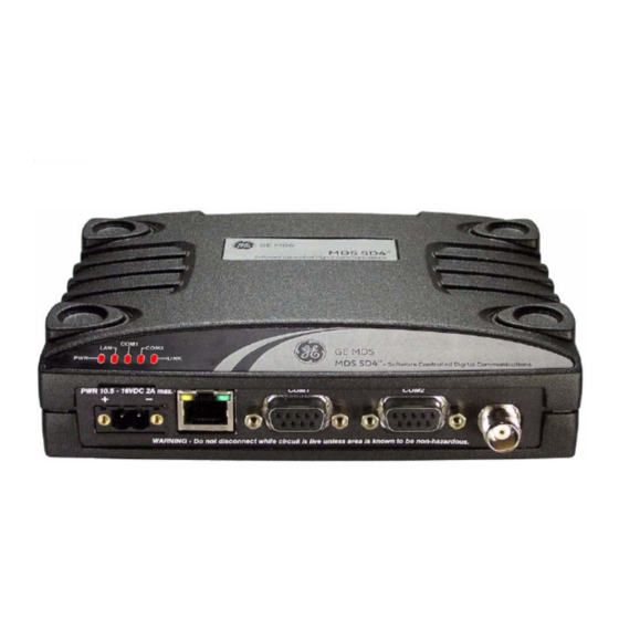
INTRODUCTION This guide presents basic installation and operating instructions for the MDS SD4 Series wireless transceiver. It is a companion guide to the MDS SD4 Series Reference Manual (Part No. 05-4670A01). Refer to the Reference Manual for detailed instructions, system design, and other technical information. - Page 4 Invisible place holder Figure 2. Front Panel Connectors & Indicators Connector functions (left to right) in Figure 2 are as follows: • POWER • (RJ-45) • Management/Diagnostics (DB-9) COM1— • Payload Data (DB-9) COM2— • (TNC) ANTENNA A list of LED functions is presented in Table 3 on Page Accessories Table 1...
-
Page 5: Installation
Table 1. SD4 Available Accessories Accessory Description Part Number DC Power Plug, Mates with power connector on 73-1194A39 2-pin, polarized radio. Screw terminals provided for wires, threaded locking screws to prevent accidental disconnect. Retrofit Kit, Digital Contains all items needed to replace 98-6190ACC1 an existing MDS x710A/C/M digital transceiver. -
Page 6: Installation Steps
ANTENNA SYSTEM TRANSCEIVER POWER SUPPLY 10.5–16 VDC @ 2A Negative Ground Only DATA TELEMETRY DEVICE Figure 3. Typical Remote Station Arrangement Installation Steps Below are the basic steps for installing the transceiver. In most cases, these steps alone are sufficient to complete the installation. Refer to the Reference Manual for additional details, if required. - Page 7 Invisible place holder 7.25˝ (16.99 cm) Figure 4. Transceiver Mounting Bracket Dimensions CAUTION Using screws longer than 1/4 inch (6 mm) to attach the brackets to the radio may damage the internal PC POSSIBLE board. Use only the supplied screws. EQUIPMENT DAMAGE 2.
- Page 8 vided with each unit (see Figure 5). Strip the wire leads to 6 mm (1/4 inch) and insert in the wire ports. Be sure to observe proper polarity as shown in the Figure Invisible place holder Lead Binding Screws (2) Retaining Screws (2) Wire Ports (2)
- Page 9 Invisible place holder Transceiver PC Running Terminal Session To COM1 Port Figure 6. PC Configuration Setup c. Set the transmit frequency by entering , where TX xxx.xxxx is the frequency in MHz. Press ENTER xxx.xxxx response indicates successful entry. PROGRAMMED OK d.
- Page 10 SOFTWARE COMMAND SUMMARY Table 2 lists software commands commonly used during initial instal- lation and setup of the transceiver. A complete list of commands and detailed descriptions is contained in the Reference Manual. Table 2. Command Summary Command Name Function BAUD [xxxx xxx] Sets radio’s serial data interface rate/format.
-
Page 11: Troubleshooting
Table 2. Command Summary (Cont’d) Command Name Function STAT Display radio status and alarms. TEMP Display the internal temperature of the radio in degrees C. TX [xxx.xxxx] Set or display the transmit frequency. TROUBLESHOOTING For proper operation, all radios in the network must meet these basic requirements: •... -
Page 12: Event Codes
Invisible place holder Figure 7. LED Indicators Table 3. LED Status Indicators LED Name Description • Continuous—Power applied, no problems detected. • Rapid flash (5 times-per-second)—Alarm indication. • Continuous—Local area network detected. • Flashing—Data is being transmitted and received. • Off—LAN not detected or excessive traffic is present. COM1/COM2 The COM LEDs show activity on the serial payload data port(s). -
Page 13: Major Alarms Vs. Minor Alarms
The codes shown are a subset of a larger pool of codes used for various GE MDS products. For this reason, the table does not show a sequential listing of all code numbers. Only the codes appli- cable to this product are shown. - Page 14 Table 4. Event Codes (Cont’d) Event Event Code Class Description Minor A data framing error has been detected on the COM2 INTERFACE connector. This may indicate a baud rate mismatch between the radio and the RTU. Minor The DC input voltage is out-of-tolerance. If the voltage is too far out of tolerance, operation may fail.
-
Page 15: Com1/Com2 Reference
Invisible place holder Figure 8. Internal Spectrum Analyzer Display COM1/COM2 REFERENCE COM1 CONNECTIONS connector is used to connect a PC to the radio for manage- COM1 ment or diagnostics. A straight-through cable is required that connects Pin 2 (RXD), Pin 3 (TXD), and Pin 5 (Ground). (See Figure Invisible place holder >... -
Page 16: Com2 Connections
COM2 CONNECTIONS connector (Figure 10) is used to connect the radio to an COM2 external DTE telemetry device that supports the EIA/RS-232 or EIA/RS-485 (balanced) format, depending on how the radio is config- ured. The radio supports data rates of 300, 1200, 2400, 4800, 9600, 19200, 38400, 57600, and 115200 bps (asynchronous data only). -
Page 17: Specifications
Table 5. COM2 Pin Descriptions—RS/EIA-232 (Cont’d) Input/ Number Output Pin Description Sleep Mode Input—Grounding this pin turns off most circuits in a remote radio. This allows for greatly reduced power consumption, yet preserves the radio’s ability to be quickly brought on line. (See Using the Radio’s Sleep Mode”... -
Page 18: Data Characteristics
TRANSMITTER Carrier Power: 0.1 Watts to 5 Watts Duty Cycle: Continuous Output Impedance: 50 Ω Channel Spacing: 6.25, 12.5, 25 kHz FCC Emission Designators: 6.25 kHz B/W (MODEM 4800F): 6K0F1D, 6K0F2D, 6K0F3D 12.5 kHz B/W (MODEM 9600, 9600M, 4800): 11K0F1D, 11K0F2D, 11K0F3D 25.0 kHz B/W (MODEM 19200): 23K4F1D, 23K4F2D, 23K4F3D... - Page 20 GE MDS, LLC 175 Science Parkway Rochester, NY 14620 General Business: +1 585 242-9600 FAX: +1 585 242-9620 Web: www.GEmds.com...
Need help?
Do you have a question about the MDS SD4 Series and is the answer not in the manual?
Questions and answers