Table of Contents
Advertisement
Quick Links
Advertisement
Table of Contents

Subscribe to Our Youtube Channel
Related Manuals for GE MDS TD220


Summary of Contents for GE MDS TD220
- Page 1 GE MDS TD220 Manual Version 12 TD220_manual12.doc Page 1 of 38 1/10/2011...
- Page 2 Table of Contents Important Information ......................3 Antenna Installation Warnings ..................3 ESD Notice ........................3 FCC Approval Notice ...................... 3 FCC Part 15 Notice ......................3 FCC Part 80 Notice ......................3 Industry Canada ICES-003 and RSS-119 ..............4 Introduction ...........................
-
Page 3: Important Information
Important Information 1.1 Antenna Installation Warnings All antenna installation and servicing is to be performed by qualified technical personnel only. When servicing the antenna, or working at distances closer than those listed below, ensure the transmitter has been disabled. Depending upon the application and the gain of the antenna, the total composite power could exceed 90 watts EIRP. -
Page 4: Industry Canada Ices-003 And Rss-119
10 W 20 W 3 dBd (5.2 dBi) 20 W 20 W 0 dBd (2.2 dBi) 1.6 Industry Canada ICES-003 and RSS-119 This Class A digital apparatus complies with Canadian ICES-003 and with RSS-119. Cet appareil numérique de la classe A est conforme à la norme NMB-003 du Canada. TD220_manual12.doc Page 4 of 38 1/10/2011... -
Page 5: Introduction
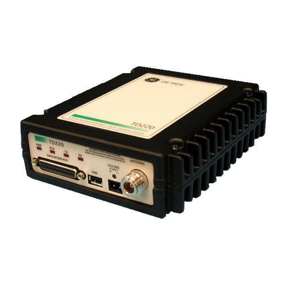
2 Introduction The GE MDS TD 220 is a 25-Watt 220 MHz GMSK data radio intended for bridging ITCS messages over the air between locomotives and wayside devices. The data interface is Ethernet, with UDP- encapsulated ITCS message payload. Each second is divided into 8 133-byte time slots. The first of the 8 timeslots each second is always reserved for bases A, B, or C to transmit beacon information to the mobiles in the area. - Page 6 BASE MOBILE UDP Header added by UDP Header stripped by Mobile Radio Base Radio IP Address and Port Number IP Address of Base Radio, to which the Mobile is Port Number on which the configured to send Base is configured to listen Payload Payload Over the Air...
-
Page 7: Interfaces
3 Interfaces 3.1 Data Interface (DB-25) The Data Interface has several ports integrated into one connector: Ethernet, COM1 and COM2 Serial Ports, and GPS signaling. Note that COM3 is connected internally and therefore not available on pins labeled with “COM3.” Notes DB-25 Direction WRT MDS... -
Page 8: Power
The radio provides a USB Port conforming to version 1.1 of the USB standard. This port is provided for future features such as ITCS logging to text files on a memory stick. Consult GE MDS for information on this feature. The pinout for this connector is given in the table below. -
Page 9: Common Setup Tasks
4 Common Setup Tasks 4.1 Key the Transmitter for Test Purposes Log in to the radio on its COM1 console using a serial terminal emulator program. Go to the Radio Configuration menu. Select the frequency for the test transmission. Select the RF Output Power to use. Note that power levels greater than 2 Watts will timeout after a 5-second period by default. -
Page 10: Set Up A Mobile Unit
4.4 Set Up a Mobile Unit If not already done, complete steps from 4.2 above. Log in to the radio. Go to the System Configuration menu. Set the unit to Mobile mode and reboot if necessary. Set the IP Port to which the mobile will send messages received over the air. Set the IP Port on which the mobile will accept incoming messages for transmission over the air. - Page 11 Test Polling Setup 40 dB/ 10 W 30 dB/ 50 W 30 dB/ 50 W TD220 Base TD220 Mobile Set for 2 Watts Set for 2 Watts Ethernet Hub 13.8 VDC < 5 Amps 13.8 VDC < 5 Amps Test PC...
- Page 12 Select a letter to configure an item, <ESC> for the prev menu Reboot the Base Obtain the Parametric Poller (parm_poller.exe) from GE MDS. This utility saves its settings to parm_poller.ini in the current directory, so make one directory for the base and a different directory for the mobile.
- Page 13 In the base directory, create the parm_poller data configuration file (parm_poller.parms) as shown below. set ::parms { { 0 "Dest" 32 "78563412" "RW" } { 1 "Src" 32 "F0DEBC9A" "RW" } { 2 "Flags" "00" "RW" } { 3 "Length" l1 "00" "RO"...
- Page 14 Configure the Mobile as follows: Lab Test Mobile System Configuration Menu -==========================================================================- A) Unit Type Mobile B) Locomotive Server 10.4.147.170 C) Locomotive Server Port 51000 D) OBC Info Packet disabled E) ITCS UDP Receive Port 52000 F) Timing Signal Timeout 60 Seconds Select a letter to configure an item, <ESC>...
- Page 15 13. If additional visibility is desired, obtain itcslog.exe from GE MDS. This utility captures messages from the logging output of the TD220 radios and displays statistics about them. The IP Port Number is the port number configured on the radio for ITCS logging.
-
Page 16: Menu Interface
5 Menu Interface Login with user name admin, password admin. When logged in, the Starting Information Screen is displayed. Parameter Description Device Name User-configured name for this radio. Set this from the Device Names menu. IP Address IP Address for this radio. Set this from the IP Networking menu. Device Status “Initializing”... -
Page 17: Main Menu
Parameter Description factory. Uptime Elapsed time since the radio was started. Current Firmware The version number of the currently operating firmware. Reprogram firmware from the Reprogramming Menu. Current User Login level. R* - This parameter is writable from another menu. 5.1 Main Menu Parameter Description... -
Page 18: Network Configuration Menus
5.2 Network Configuration Menus Parameter Description A) IP Configuration Access the IP Configuration menu to set the IP Address, Netmask, and Gateway IP Address. B) SNMP Agent Access the SNMP Agent Configuration Menu. Configuration Ethernet Address Displays the hardware MAC address for the Ethernet port. TD220_manual12.doc Page 18 of 38 1/10/2011... - Page 19 Parameter Description A) IP Address The IP address that this radio will use for its Ethernet interface. B) IP Netmask The subnet mask for the network this radio is part of. C) IP Gateway The IP address of the gateway that will pass traffic from the radio’s subnet to nodes on other networks.
- Page 20 Community This string can be up to 30 alphanumeric characters. D) SNMP v3 Auth Authentication password stored in flash. Will be used when Agent Password is managing passwords locally or initially for all cases on reboot. This is the SNMPv3 password used for Authentication (currently only MD5 is supported).
-
Page 21: Base System Configuration Menus
5.3 Base System Configuration Menus Parameter Description A) Unit Type Bases send beacons out once per epoch and coordinate downstream messages. Mobiles listen to bases to identify free slots, and then select random slots in which to place their upstream messages. B) Base Unit Zone Bases are one of three types, A, B, and C. - Page 22 Parameter Description A…) ITCS Translation Each entry in this table contains a 32-bit Destination ITCS Table Entry Address, a 32-bit ITCS Address Mask, an IP Address and port, and the RSSI Option. Any incoming ITCS message is bitwise anded with the mask. If the result matches the Destination ITCS Address, the message is sent to the IP Address and Port given.
-
Page 23: Mobile System Configuration Menu
5.4 Mobile System Configuration Menu Parameter Description A) Unit Type Bases send beacons out once per epoch and coordinate downstream messages. Mobiles listen to bases to identify free slots, and then select random slots in which to place their upstream messages. B) Locomotive Server The IP Address of the OBC to receive messages from this radio. -
Page 24: Radio Configuration Menu
5.5 Radio Configuration Menu Parameter Description A) Base Transmit The frequency in the 217.44625 to 221.95625 MHz range that the Frequency Base Units use for over the air transmissions. B) Mobile Transmit The frequency in the 217.44625 to 221.95625 MHz range that the Frequency Mobile Units use for over the air transmissions. -
Page 25: Gps Configuration Menu
5.6 GPS Configuration Menu Parameter Description A) GPS NMEA Baud This is the Baud Rate used on the radio port to receive NMEA Rate Sentences. B) GPS PPS Polarity Indicates if the TTL PPS Pulse is Active High (Positive Pulse) or Active Low (Negative Pulse). -
Page 26: Statistics/Logging Menus
Parameter Description A) Telnet Access If “enabled”, the radio allows users to Telnet to the radio via Ethernet. If “disabled”, users must manage the radio via SNMP or the serial console. B) User Passwords Allows modification of the admin password. F) SNMP Mode This specifies the mode of operation of the SNMP Agent. - Page 27 Parameter Description A) ITCS Logging If “enabled”, send UDP messages to a logging host. B) ITCS Log Server The IP address to send UDP messages for logging ITCS traffic. C) ITCS Log Server Port The IP port number to send UDP messages for logging ITCS traffic. Parameter Description Packets Received...
- Page 28 Parameter Description Base A RSSI The RSSI of the last message received from Base A. Base A Slot The Timeslot the last message from Base A was received in. Base B RSSI The RSSI of the last message received from Base B. Base B Slot The Timeslot the last message from Base B was received in.
- Page 29 Parameter Description A) Current Alarms Display a list of the alarms currently active within the radio. B) View Event Log Scroll through the historical list of radio events and alarms. C) Clear Event Log Erase all history of radio events and alarms. D) Send Event Log Begin a TFTP transfer of the historical list of all radio events to the IP Address given by “Event Log Host Address”.
-
Page 30: Device Information Menus
5.9 Device Information Menus Parameter Description Model The Model Type of the radio. Serial Number The factory-assigned unique radio Serial Number. Uptime The number of elapsed hours, minutes, and seconds since the radio last rebooted. Date The Date from the GPS receiver. Time The Time from the GPS receiver. -
Page 31: Maintenance/Tools Menus
Parameter Description A) Device Name Free-form field where you can enter a nickname for this radio. B) Contact Free-form field where you can indicate who to contact in case the radio needs service. C) Location Free-form field where you can describe the site at which the radio is installed. - Page 32 Parameter Description A) TFTP Host Address The IP address of the TFTP server from which you will download a new firmware image. B) Firmware Filename The file name for the firmware image. This file must exist on the server. C) TFTP Timeout If the radio cannot reach the TFTP server, it waits this long before giving up at each step in the process.
- Page 33 Configuration scripts are used to store and duplicate radio settings. To use this facility, send the configuration file from a radio to the TFTP server. It can then be archived or edited and retrieved from the same or different radios. For more information, contact GE MDS. Parameter...
-
Page 34: Troubleshooting
6 Troubleshooting Here are some tips to help resolve issues when operating the TD220. Symptom Possible Cause Radio is alarmed (PWR LED is flashing) Check the alarm list accessible from the Starting Information Screen. Alarm: GPS PPS Not Available Radio is not receiving a PPS. -
Page 35: Itcslog Utility
7 ITCSLOG Utility The ITCSLOG utility is a PC program that receives, displays and captures logging messages sent from TD220 radios. ITCSLOG messages are diagnostic messages used to track and analyze the message flow between radios. The radios generate two log messages for each payload message it processes. The first message is the Header Message and it contains the information about the processing of the payload message. - Page 36 Parameter Action Description IP Port Number The port this program will use to receive ITCSLOG messages. This program can collect log messages from multiple radios as long as they have an Ethernet connection and are configured with the correct IP Address and Port Number. Start Monitoring Button Causes the program to start processing log messages.
- Page 37 2010-06-11 14:11:47: 31 50 31 5f 38 33 35 31 32 32 34 30 32 31 33 36 31 32 35 33 39 33 37 39 39 31 34 31 30 31 35 33 30 39 34 30 31 32 39 39 39 33 32 35 34 32 39 36 31 30 32 33 31 36 31 31 31 30 39 38 38 31 33 30 39 37 37 37 33 32 37 39 39 31 39 39 31 38 34 31 31 33 35 35 32 31 31 31 30 34 31 30 37 30 34 35 31 30 39 35 2010-06-11 14:11:47: Received 12 bytes from 10.4.199.100 1027:...
-
Page 38: Change Log
8 Change Log Version Date Author Changes 11/19/2009 T. Mayo Added change log. • Added correct product photos. • Added figures to describe IP traffic mechanism. • 1/25/2010 T. Mayo Corrected polling instructions to adjust the IP ports to • use with the Base and Mobile Parm Poller programs.
Need help?
Do you have a question about the TD220 and is the answer not in the manual?
Questions and answers