Table of Contents
Advertisement
Quick Links
Advertisement
Table of Contents

Related Manuals for Analog way Vertige VRC300


Summary of Contents for Analog way Vertige VRC300
- Page 1 USER MANUAL Vertige™ Ref. VRC300...
- Page 2 Information contained in this document, in particular data, pictures, information, trademarks and logos are exclusive property of Analog Way and are protected by copyrights and other intellectual property rights. 2014, Analog Way, all rights reserved – 01/2018 Consequently, any representation and/or reproduction, in part or in full, is prohibited and would be considered a violation of Analog Way’s copyright and other intellectual property rights.
-
Page 3: Table Of Contents
THANK YOU By reading this manual you will be able to obtain the most from your powerful Vertige™. 1. INTRODUCTION 1.1 What is the Vertige™ 1.2 Useful terms and definitions 2. HARDWARE INSTALLATION 2.1 Safety instructions 2.2 Environmental specifications 2.3 Hardware specifications 2.4 Unpacking and inspection 2.5 The Vertige™... - Page 4 5. OPERATING THE VERTIGE™ 5.1 Layer section 5.1.1 Selecting layers from the touchscreen 5.1.2 Selecting layers from the front panel 5.1.3 Selecting layers on Program vs Preview 5.1.4 Using the layer selection modifier keys 5.2 Source section 5.2.1 Making live switching directly to Program 5.2.2 Switching between plugs on the device inputs 5.3 Preset section 5.3.1 How to save a preset...
-
Page 5: Introduction
1.1 What is the Vertige™ 1. INTRODUCTION 1.1 What is the Vertige™ Vertige™ is a revolutionary Remote Controller integrating new ways to create and manage large events and multi-venues. The Vertige™ brings a simple and flexible approach to show creation and management. Vertige™ can control several screens and devices such as Ascender 48 - 4K - PL, Ascender 32 - 4K - PL, Ascender 16 - 4K, SmartMatriX Ultra, NeXtage 16 - 4K or NeXtage 08 - 4K systems, independently or simultaneously in any kind of combination, including Soft Edge Blending. -
Page 6: Hardware Installation
2.1 Safety instructions 2. HARDWARE INSTALLATION 2.1 Safety instructions 2.1.1 English For optimal use of this device, read all safety and operating instructions before use. Keep the safety and operating instructions for future reference. Please follow all of the warnings on this product and its operating instructions. - Page 7 2.1 Safety instructions 2.1.2 French Pour une utilisation optimale de cet appareil, nous vous conseillons de bien lire toutes les consignes de sécurité et de fonctionnement avant utilisation. Conservez les instructions de sécurité et de fonctionnement afin de pouvoir les consulter ultérieurement. Respectez toutes les consignes marquées dans la documentation, sur le produit et sur ce document.
- Page 8 2.1 Safety instructions 2.1.3 Italian Per un utilizzo ottimale dell’apparecchio, leggere tutte le istruzioni di sicurezza e di utilizzo prima dell’uso. Conservare le istruzioni di sicurezza e di funzionamento al fine di poterle consultare ulteriormente. Seguire tutti i consigli indicati su questo manuale e sull’apparecchiatura. •...
- Page 9 2.1 Safety instructions 2.1.4 German Zum optimalen Gebrauch dieses Gerätes lesen Sie bitte vorher alle Sicherheits- und Bedienhinweise. Diese Sicherheits- und Betriebsanweisungen für einen späteren Gebrauch sicher aufbewahren. Alle in den Unterlagen, an dem Gerät und hier angegebenen Sicherheitsanweisungen einhalten. •...
- Page 10 2.1 Safety instructions 2.1.5 Spanish Para un uso óptimo de este equipo, lea las instrucciones de seguridad y operación antes de utilizarlo. Conserve las instrucciones de seguridad y de funcionamiento para que pueda consultarlas posteriormente. Respete todas las consignas indicadas en la documentación, relacionadas con el producto y este documento. •...
-
Page 11: Environmental Specifications
2.2 Environmental specifications 2.2 Environmental specifications • Cooling air flows from front side to rear. • Max ambient operating temperature: < 40°C (< 104°F). • Operating temperature: 0 to +40°C / +32°F to +104°F • Storage temperature: -40 to +70°C / -40°F to +158°F •... -
Page 12: Hardware Specifications
2.3 Hardware specifications 2.3 Hardware specifications Dimensions: Weight: Shipping Weight: W 740 x D 510 x H 200 mm 15 kg / 33 lbs 20 kg / 44 lbs W 29.2” x D 20.0” x H 7.9” Electrical Requirements: Required Voltage: 100-240 VAC Required Amperage: 2.5A between the two power supplies... -
Page 13: The Vertige™ Front Panel
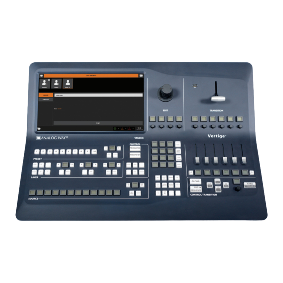
3.1 Overview 3. THE VERTIGE™ FRONT PANEL 3.1 Overview 1- Touch screen The touch screen 15’’6 Wide displays comfortably on the same page the representation of the Program & Preview of a typical scene (Blend + 2 satellites). It is important to have the whole scene represented to work on multiple layers from different screens at the same time (change of source of background, for example). -
Page 14: Color Codes
3.2 Color codes 6- Edit section 7- Transition section This section allows the operator to edit the selected This section enables the operator to use the T-Bar layers in three different ways: roughly via the and sliders for transitions. Sliders allow individual joystick, finely via the encoders, or directly via the scene mixing. -
Page 15: Starting With The Vertige
4.1 System configuration 4. STARTING WITH THE VERTIGE™ 4.1 System configuration When the Vertige™ starts up, the Home page is automatically displayed. Press the START button, then press the Vertige™ SETTINGS button in the upper-right corner. • Configuring the system time: In the top bar, select the Time tab. -
Page 16: User Selection
4.2 User selection 4.2 User selection The User Selection page allows you to login and manage user accounts: • Creating a new user account: CREATE In the left menu, select the option. Enter the user’s name. If this user account needs to be password- protected then enter the corresponding Password Confirm... -
Page 17: Show Selection
4.3 Show selection 4.3 Show selection Show Selection page allows you to manage shows for the currently logged-in user: • Creating a new show: In the left menu, select the CREATE option then enter the name of the show. Check the Share box if you intend to share this show with any other users... - Page 18 4.4 Iteration selection • Creating a new iteration: In the left menu, select the CREATE option then enter a description for this iteration. When ready, press the Create button. You can also press the Create & Load button to create the iteration and load it automatically.
-
Page 19: Iteration Wizard
4.5 Iteration Wizard • Importing an iteration from a USB key: In the left menu, select TRANSFER then select the IMPORT option. Plug a USB flash drive into one of the Vertige™ USB connectors. Select your USB flash drive in the Storage list to display the iterations available. - Page 20 4.5 Iteration Wizard Wizard Step 2 (Devices): Enter the IP address of the Master device. If you have selected the Synchronized option, then check the Slave #X boxes to enable up to three additional devices that will be synchronized with the Master device.
-
Page 21: Assembly Configuration
4.6 Assembly configuration When ready, press the Create button to automatically create the assembly as well as the related devices, screens, scenes, streams, sources and front panel key bindings (with predefined default values). Once completed, the Wizard returns to the first page and the above area is updated to reflect the latest changes and the newly created screens. - Page 22 4.6 Assembly configuration • Two LiveCore™ devices linked together using the set of Link cables (additive modularity), for example: • One LiveCore™ device linked to an optional LiveCore™ Output Expander (LOE) using the set of Link cables (additive modularity), for example:...
- Page 23 4.6 Assembly configuration • Up to 4 identical LiveCore™ devices synchronized together (associative modularity). In this configuration, all the devices must be connected to Vertige™ and all the sources should be split for each device, for example: In order to synchronize the LiveCore™ devices, use Ethernet cables between the IN and OUT device sync. connectors.
- Page 24 4.6 Assembly configuration The Vertige™ can handle several device assemblies. To manage your assemblies, go to the Assembly page: • Creating a new assembly: Select the CREATE option in the left menu and then enter the name of the assembly. In the Device Type field, select the type of device that will be handled...
- Page 25 4.6 Assembly configuration Note: The Vertige™ will automatically try to connect to the device regularly. Once the device is successfully connected, the icon next to the device will turn green. If no connection status is available, a question mark will be displayed. To remove a device, simply uncheck its corresponding box in the list.
- Page 26 4.6 Assembly configuration • Configuring output resources: In the left menu, select the PRECONFIG / OUTPUT option and then select the assembly for which you want to configure output resources. If the assembly contains more than one device, select the required Master/Slave device.
- Page 27 4.6 Assembly configuration • Configuring HDCP detection: In the left menu, select the PRECONFIG / HDCP option then select the assembly for which you want to quickly configure HDCP detection. - OUTPUTS panel: Press the NONE button to disable HDCP detection on all the devices outputs.
- Page 28 4.6 Assembly configuration • Configuring the device(s) inputs: In the left menu, select the IN/OUT / INPUT option then select the assembly for which you want to configure the inputs: To automatically configure all the inputs, simply press the All inputs button located in the AUTO SET...
-
Page 29: Matrix Configuration
4.7 Matrix configuration When a valid media is assigned to a frame, the corresponding item will be underlined with a thin blue line. When done, press the Apply button to save your changes. To delete a Frame stream, simply select the corresponding item in the list and press the Remove button. - Page 30 4.7 Matrix configuration Example 1: One single device assembly (NeXtage 16 - 4K). In this setup, an 8x8 SDI matrix increases the number of SDI signals available on the LiveCore™ device. With 4 links between the matrix and the LiveCore™ device, up to 4 different matrix streams among the 8 can be displayed on Program.
- Page 31 4.7 Matrix configuration Example 2: One assembly with two synced LiveCore™ devices (associative modularity). In this setup, an 8x8 SDI matrix increases the number of SDI signals available and distributes them on each LiveCore™ device. With 4 links between the matrix and each LiveCore™ device, up to 4 different matrix streams among the 8 can be displayed on Program.
- Page 32 4.7 Matrix configuration Example 3: One Ascender 16 - 4K assembly and one Ascender 48 - 4K - PL assembly. In this setup, an 8x8 SDI matrix increases the number of SDI signals available and distributes them on each LiveCore™ device. With 2 links between the matrix and the Ascender 16 - 4K, up to 2 different matrix streams among the 8 can be displayed on Program.
- Page 33 4.7Matrix configuration To display the Matrix configuration page, select the Iteration tab in the top menu bar and then select the MATRIX option on the left. • Creating a new matrix router: Select the CREATE option in the left menu and then enter the name of the matrix router.
- Page 34 4.7 Matrix configuration • Mapping matrix outputs to the assembly inputs: Go to the Assembly page on the top bar. Select the PRECONFIG / MATRIX option and then select the assembly for which you want to configure the assembly matrix mapping. To add a new link, select the matrix router and then select a MATRIX...
-
Page 35: External Device Configuration
4.8 External device configuration 4.8 External device configuration With the Vertige™, you can control one or more external devices over IP. Media players, PTZ cameras, and nearly any device that supports TCP, UDP or HTTP protocols can be this way controlled via the Vertige™. If your setup includes an external device, you need to: - Add the external device to your iteration (specify the device type, configure the LAN settings ...). -
Page 36: Screen Configuration
4.9 Screen configuration 4.9 Screen configuration A «Screen» is a destination where a picture can be displayed (a single display, a projection surface composed of several outputs ...), and it can use one or several layer resources. Screen page allows you to manage screens: •Creating a new screen: CREATE Select the... - Page 37 4.9 Screen configuration - In Custom Canvas mode, select an Area and then configure: - Position: Position the area in the screen. - Format: Choose the output format for the selected screen area. Available selection filters include Internal (internal rate), Standard (requires Rate selection) or Custom...
- Page 38 4.9 Screen configuration Once your covering area is well defined, you need to adjust the black levels: select the BLACK option then select an area into the overview of your Soft Edge to display the corresponding settings on the right panel. Then adjust the black levels for each side using the R,G,B sliders.
-
Page 39: Scene Configuration
4.10 Scene configuration 4.10 Scene configuration In the Vertige™, a Screen can be processed by only one Assembly, therefore by only one kind of LiveCore™ device. A Screen is also limited by the LiveCore™ architecture to a maximum of 24 layers on 4 outputs or 6 layers on 16 outputs. -
Page 40: Confidence Screen Configuration
4.11 Confidence Screen configuration 4.11 Confidence Screen configuration The Confidence page allows you to manage Confidence screens: • Configuring the layout and widget(s) source: Select the LAYOUT option in the left menu then select the Confidence screen for which you want to configure the current layout. -
Page 41: Monitoring Configuration
4.12 Monitoring configuration • Renaming a Confidence preset: Select the LOAD option in the left menu then select one of the memory slots to automatically recall the corresponding Confidence preset from memory. Enter a description for this Confidence preset then press the Apply button. - Page 42 4.12 Monitoring configuration • Saving a monitoring preset to memory: Select the SAVE option in the left menu then select the monitoring output for which you want to save the current configuration to memory (16 memory slots available). Select the slot where the current configuration will be saved and optionally enter a description.
-
Page 43: Source Configuration
4.13 Source configuration 4.13 Source configuration «Sources» are the keys you see on the Vertige™ front panel (SOURCES section). They allow you to assign a stream per screen to a front panel key, so that you can later select the streams to display on layers via the front panel keys. -
Page 44: Native Source Configuration
4.14 Native source configuration 4.14 Native source configuration Native sources are sources specific to native background layers. To manage your native sources, go to the Source page on the top bar and make sure the Native tab is highlighted: • Creating a new native source: Select the CREATE option in the left... -
Page 45: Stream Image Configuration (Before The Event Has Started)
& white range. - CREMATTE®: The algorithm of color keying developed by Analog Way. This keying will perform advanced effects on transparent items, smooth edge and color correction. Keying setup can be done either by setting directly color references and tolerances or by using an assistant... -
Page 46: Stream Image Configuration (During The Event)
4.16 Stream image configuration (during the event) 4.16 Stream image configuration (during the event) In the Preset page, press the IMAGE SETTINGS button to display the stream image settings menu while maintaining a minimal view on the Preview or Program preset. Select the layer containing the streams for which you want to configure the image settings then select the ASPECT,... -
Page 47: Preset Management
4.18 Preset management 4.18 Preset management In the Preset page, press the PRESET GRID button to display the preset menu while maintaining a minimal view on the Preview or Program preset. • Saving a preset to memory: To save a preset from Program, make sure that the PROGRAM button is... -
Page 48: Macro Management
4.19 Macro management • Erasing a preset memory: Select the CLEAR option in the left menu then select the desired memory slot. When ready press the Clear button to erase it. To restore the default Preset page view, simply press the MAXIMIZE button. - Page 49 4.19 Macro management You can then add different types of actions to the macro: - External action Choose Action Type > External to add an external device action. Select the device from the Device drop-down menu (note that for the device to be available it must have been added to the iteration before- hand - see External device configuration) then select the device Action you want...
-
Page 50: Sequence Management
4.20 Sequence management 4.20 Sequence management Sequence page allows you to define a series of cue steps that can be played back sequentially via the Vertige front panel (CONTROL TRANSITION section). Each cue step is defined by a trigger (hotkey, fixed duration ...) and an action (load preset, take ...), and it is stored in a cue stack that is itself organized within the sequence. - Page 51 4.20 Sequence management • Adding a cue step: Select an existing cue step (the selection should be highlighted in orange) then select the EDIT option. Press button located on the left to insert a new cue step before the selected cue step, or press the button located on the right to add a new cue step after the selected cue step.
-
Page 52: External Controllers
These descriptors are small documents that describe the matrix router capabilities and its external communication protocol. If your device is not in this default list, please contact Analog Way Technical Support: based on your matrix reference and user manual, we might be able to generate a descriptor that you can then import into your Vertige™. - Page 53 4.22 Matrix library configuration • Exporting a matrix descriptor to USB key: In the left menu, select TRANSFER then select the EXPORT option. Select the matrix descriptor you want to export and plug a USB flash drive into one of the Vertige™...
-
Page 54: External Device Library Configuration
4.23 External device library configuration 4.23 External device library configuration The Vertige™ provides a list of external device descriptors that allows you to easily control some popular A/V devices. These descriptors are small documents that describe the type of actions supported by the device and the device external communication protocol. - Page 55 4.23 External device library configuration • Exporting an external device descrip- tor to USB key: In the left menu, select the TRANSFER tab and then the EXPORT option. Select the external device descriptor you want to export and then plug a USB flash drive into one of the Vertige™...
-
Page 56: Operating The Vertige
5.1 Layer section 5. OPERATING THE VERTIGE™ 5.1 Layer section To be able to make a source selection using the Vertige™ console, you must first select at least one layer. The Vertige™ layer selection buttons are powerful tools for fast and efficient selection of layers for source selection and layer manipulation. -
Page 57: Selecting Layers On Program Vs Preview
5.1.3 Selecting layers on Program vs Preview 5.1.3 Selecting layers on Program vs Preview At all times of operation, the focus of the preset editing will always be on either Program or Preview. If you are working on Program, the large PROGRAM button will be lit, and the Program section will be highlighted on the touchscreen. -
Page 58: Source Section
5.2.1 Making live switches directly to Program Select all PIP layers on side scenes To select the PIP layers (layers 2 and 3 for example) on the side scenes (Left Scene and Right Scene in this example), there are several options, depending on your preferred work style: You could select the first layer using the touchscreen, then press and hold the and select the additional layers using the touchscreen. -
Page 59: Preset Section
5.3.1 How to save a preset 5.3 Preset section Presets can be saved, loaded and renamed directly from the Preset page on the touchscreen. For more information please read chapter 4.18 Preset management. 5.3.1 How to save a preset To save a preset, first create the content that you wish to save on either the Program or Preview scenes. To save a preset from Program, make sure that the Program button is selected. -
Page 60: Control Section
5.4 Control section 5.4 Control section Into the control section, you can choose to work on Program or Preview. Simply press the Program or Preview button to choose where to work. Remember that the Program/ Preview control change when you press a layer on the touchscreen. •... - Page 61 5.5 Edit section • SIZE button: Using the size attributes, you can adjust the size of your PIP using the X, Y or Z (keep the H&V ratio) axes of the joystick or giving to the PIPs the right aspect ratio thanks to the contextual menu. You will also find four convenient shortcuts: Screen Size (full scene size), Quad Size (1/4 of the scene), Stream Ratio (aspect ratio of the stream displayed) and Stream Size (1 :1).
- Page 62 5.5 Edit section You can also use the fine tuning buttons to modify the start and the end of the opening/closing. For example, select the desired effect and then set up the start of the opening at 40% and end at 80%. During the take, this layer will start its effect at 40% of the global take duration and finish at 80% of the global take duration.
-
Page 63: Transition Section
5.6 Transition section Macros MACRO button, located to the right of the EDITpad, provides access to macros and allows you to manually run macros via the front panel macro keys. To run a macro, first enable the MACRO button to access the macro keys on the EDITpad (the 12 contextual LCD keys will be highlighted to display macros). -
Page 64: Control Transition Section
5.7.1 Controlling the transition 5.7 Control transition section Into the control transition section, you can choose either to control the transition (default section behavior) or to control the cue sequence playback. 5.7.1 Controlling the transition • FILTER SELECT button: FILTER SELECT button allows you to quickly edit the transition filter based on current layer selection. - Page 65 5.7.2 Controlling the cue sequence playback • STOP button: Pressing the STOP button stops the cue sequence playback (the playhead remains at its current position). • PREV button: PREV button allows you to play the selected cue and to move back to the previous cue (step-by-step playback).
-
Page 66: Mechanical Diagram
6. Mechanical diagram 6. MECHANICAL DIAGRAM 740,0 mm 290,2 mm 124,2 mm 740,0 mm 290,2 mm 124,2 mm 5,4 mm 520,5 mm 740,0 mm 290,2 mm 124,2 mm 98,5 mm 740,0 mm 740,0 mm 290,2 mm 27,0 mm 358,1 mm 124,2 mm 740,0 mm 290,2 mm... -
Page 67: Warranty
• Analog Way’s direct employees are solely authorized to make this determination. • Analog Way reserves the right to refuse for repair and service a product for which the warranty is void. • In no way shall Analog Way be responsible for direct or indirect loss of profit or consequential damages resulting from any defect in this product. -
Page 68: Contact Information
UNITED STATES SINGAPORE The Americas Europe, Middle East & Africa Asia Pacific Analog Way SAS - Headquarters Analog Way Inc. Analog Way Pte Ltd Tel.: +33 (0)1 81 89 08 60 Tel.: +1 (678) 487 6644 Tel.: +65 6292 5800... - Page 69 Follow us Firmware: V05 - VRC300 - 22/JAN/2018...
Need help?
Do you have a question about the Vertige VRC300 and is the answer not in the manual?
Questions and answers