
Related Manuals for Avocent SwitchView SC


Summary of Contents for Avocent SwitchView SC
- Page 1 ® WITCH Installer/User Guide Avocent Corporation 4991 Corporate Drive Huntsville, Alabama 35805-6201 • USA (Tel) 256-430-4000 (Fax) 256-430-4030 http://www.avocent.com...
- Page 3 ©2003 Avocent Corporation. All rights reserved. Avocent is a trademark of Avocent Corporation. IBM, PC, PC/AT and PS/2 are registered trademarks of International Business Machines Corporation. Cybex, the Cybex logo, AutoBoot and SwitchView are trademarks or registered trademarks of Cybex Computer Products Corporation. IntelliMouse is a trademark of Microsoft Corporation. All other marks are the...
- Page 4 FCC Notifi cation Warning: Changes or modifi cations to this unit not expressly approved by the party responsible for compliance could void the user's authority to operate the equipment. Note: This equipment has been tested and found to comply with the limits for a Class B digital device, pursuant to Part 15 of the FCC Rules.
-
Page 5: Table Of Contents
Table of Contents Chapter 1 - Product Overview Feature Overview... 1 Compatibility ... 3 Chapter 2 - Installation Basic Install... 5 Chapter 3 - Operations Overview... 9 Chapter 4 - Appendices A: Specifi cations ... 11 B: Troubleshooting... 12... - Page 6 POWER ON: This symbol indicates the principal on/off switch is in the on position. POWER OFF: This symbol indicates the principal on/off switch is in the...
-
Page 7: Chapter 1 - Product Overview
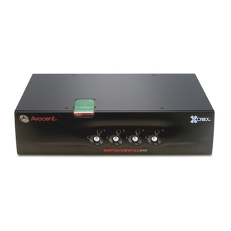
Support for up to eight computers and mouse. Each computer can be up to 30 feet away from the SwitchView SC unit. The unit works with IBM PC/AT and PS/2 systems, and 100% compatible machines with support for VGA, SVGA, XGA and XGA-II video. PS/2 keyboard and PS/2 mouse peripherals are supported through the rear of the unit. - Page 8 SwitchView SC Installer/User Guide Indicator LEDs give you constant readings on the status of your SwitchView SC. Status indicator LEDs Channel LEDs take the guesswork out of system operation and diagnostics. A typical SwitchView SC confi guration is shown below.
-
Page 9: Compatibility
Compatibility The SwitchView SC requires a PS/2 mouse and keyboard. The following mice are PS/2 peripherals known to be compatible: Other manufacturers' mice may operate with the SwitchView SC. If you experience problems using an untested mouse, contact Avocent Technical Support with the manufacturer and model number of the mouse. - Page 10 SwitchView SC Installer/User Guide...
-
Page 11: Chapter 2 - Installation
• Rack mounting kit (optional) Connecting peripherals to the SwitchView SC 1. Power down all computers that will be part of your SwitchView SC system. Do not use the SwitchView SC unit if the two tamper evident security stickers are not in place on the top of the unit. - Page 12 1. Locate your first input cable. It will have a 25-pin “D” connector at one end. Plug this cable into any available lettered channel port on the rear of the SwitchView SC. The other end of the input cable will have three connectors: a 15-pin “HDD” connector for your video, a 6-pin miniDIN connector for a PS/2 keyboard connection and a 6-pin miniDIN connector for a PS/2 mouse connection.
- Page 13 2. Locate your next input cable. Repeat step 1 until all computers are properly attached to the SwitchView SC. 3. Locate the power cord that came with your SwitchView SC unit. Plug it into the IEC power connector on the unit and make sure that the power switch is off.
- Page 14 SwitchView SC Installer/User Guide...
-
Page 15: Chapter 3 - Operations
Operations Overview PCs may be powered up one at a time or all at once. No operator intervention is required during booting. As the system stabilizes, the green LEDs over each channel will light, indicating that the attached computer is powered. The amber LED will light at the active computer. - Page 16 SwitchView SC Installer/User Guide...
-
Page 17: Chapter 4 - Appendices
Appendices A: Specifi cations Mechanical Environmental/Power Supported Hardware Agency Approvals Height: 1.7" (4.5 cm) Width: 17.2" (43.7 cm) Depth: 8.5" (21.6 cm) Weight: 6.3 lbs (2.9 kg) Operating Temperature: 41° (5°C) to 104° (40°C) Storage Temperature: -4° (-20°C) to 122° (50°C) Input Power: 8.0 W Operating Voltage: 100 - 230 VAC Power Frequency: 50 - 60 Hz... -
Page 18: B: Troubleshooting
If not, try another mouse. Verify that the cables from the PC to the SwitchView SC are connected properly. Verify that the keyboard is plugged into the keyboard port in the User Console area on the rear... - Page 19 Avocent Corporation warrants to the original retail purchaser that this product is and will be free from defects in materials and workmanship for a period of 24 months from the date of purchase. Additionally, all Avocent products carry an unconditional thirty-day satisfaction guarantee. If, for any reason, you are dissatisfi...
- Page 20 590-323-001B...
Need help?
Do you have a question about the SwitchView SC and is the answer not in the manual?
Questions and answers