Advertisement
o p E R At i n G i n S t R U c t i o n S M A n U A L
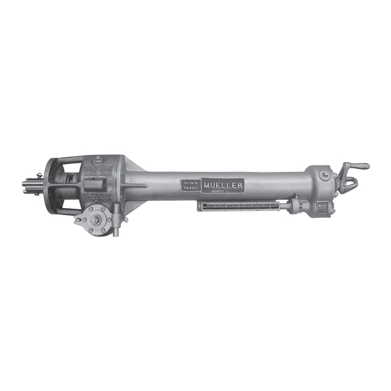
MUELLER
GAS
C1-36
Drilling
Machine
!
WARNING:
1. Read and follow instructions carefully. Proper training and periodic
review regarding the use of this equipment is essential to prevent possible
serious injury and/or property damage. The instructions contained
herein were developed for using this equipment on fittings of Mueller
manufacturer only, and may not be applicable for any other use.
2. Do noT exceed the pressure ratings of any components or equipment.
Exceeding the rated pressure may result in serious injury and/or property
damage.
3. Safety goggles and other appropriate protective gear should be used.
Failure to do so could result in serious injury.
4. Pressure test, check for and repair leaks in all fittings and components
each time one is installed or any joint or connection is broken. Failure
to find and repair a leak from any source in the fittings, by-pass lines
or equipment could result in an explosion and subsequent serious injury
and/or property damage.
5. MUELLER
Drilling Machines and Equipment have been carefully
®
designed and engineered to work together as a unit. The use of equipment
manufactured by someone other than Mueller Co. may cause excessive
wear or a malfunction of the MUELLER machines.
®
All warranties, expressed or implied, for Mueller Drilling Machines are
rendered null and void if the machines are used with shell cutters or
equipment manufactured by someone other than Mueller Co.
TAbLE oF ConTEnTS
General Information
Maintenance Instructions
Operating Instructions
Travel Charts
Installation Instructions:
Replacing Feed Knob
with Auto-Feed Lever
Reliable Connections
Customer Service Center
Decatur, Illinois
800.798.3131
www.muellergas.com
moreinfo@muellercompany.com
PAGE
2
3
4-6
7-10
11
TM
Advertisement
Table of Contents

Related Manuals for Mueller C1-36


Summary of Contents for Mueller C1-36
- Page 1 The instructions contained Reliable Connections herein were developed for using this equipment on fittings of Mueller manufacturer only, and may not be applicable for any other use. 2. Do noT exceed the pressure ratings of any components or equipment.
-
Page 2: General Information
C1-36 Drilling Machines ® General Information Machine Weight/Length Chart Capacity and Use For complete information on the The C1-36 Drilling Machine is power uses of these machines and the desCRIptIoN C1-36 operated for making cuts from equipment and attachments required Machine &... -
Page 3: Maintenance Instructions
WITH AN OILSTONE BEFORE 88150) counter-clockwise and EACH CUT. If the cutters are advance boring bar 6 or 8 inches. very dull, return to Mueller Co. for This will cause the gland to move reconditioning. forward into an exposed position. -
Page 4: Operating Instructions
10 for travel chart. opening is clear and unobstructed a) 1½”– 2”/Dn40 – Dn50. Remove a) When using the C1-36 Machine and the cutter will pass freely. the retaining screws from the and Mueller Air or Hydraulic shank of the drill. - Page 5 19. Advance boring bar by rotating pages 7–10 for travel chart). extensive damage to the machine. feed crank counter-clockwise and this applies to C1-36 machines 15. Check completion of cut by remove hub retaining bolt, (retaining manufactured prior to september...
-
Page 6: Operating Instructions
MUELLER C1-36 Drilling Machines ® Operating Instructions Overtravel Feature Re-engaging overtravel Feature 3. Remove the cotter pin from the feed screw nut which is located in To re-engage the boring bar after it the center of the crank hub at the... -
Page 7: Travel Charts
MUELLER C1-36 Drilling Machines ® Travel Charts tRAVeL ReQUIRed to CoMpLete A CUt FoR LAteRAL CoNNeCtIoN WItH poINt oF pILot dRILL (oR soLId dRILL) CoNtACtING MAIN AsBestos CAst IRoN pIpe steeL pIpe CeMeNt pIpe Nominal Outside Nominal Outside ASA A 21.6.1953 ASA A 21.6.1953... - Page 8 MUELLER C1-36 Drilling Machines ® Travel Charts tRAVeL ReQUIRed to CoMpLete A CUt FoR LAteRAL CoNNeCtIoN WItH poINt oF pILot dRILL (oR soLId dRILL) CoNtACtING MAIN AsBestos CAst IRoN pIpe steeL pIpe CeMeNt pIpe Nominal Outside ASA A 21.6.1953 AWWA...
- Page 9 MUELLER C1-36 Drilling Machines ® Travel Charts tRAVeL ReQUIRed to CoMpLete A CUt FoR LAteRAL CoNNeCtIoN WItH poINt oF pILot dRILL (oR soLId dRILL) CoNtACtING MAIN AsBestos CAst IRoN pIpe steeL pIpe CeMeNt pIpe Nominal Outside ASA A 21.6.1953 ASA A 2.1953...
-
Page 10: Travel Charts
MUELLER C1-36 Drilling Machines ® Travel Charts tRAVeL ReQUIRed to CoMpLete A CUt FoR LAteRAL CoNNeCtIoN WItH poINt oF pILot dRILL (oR soLId dRILL) CoNtACtING MAIN AsBestos CAst IRoN pIpe steeL pIpe CeMeNt pIpe Nominal Outside ASA A 21.6.1953 ASA A 2.1953... -
Page 11: Replacing Feed Knob With Auto-Feed Lever
(C.) 6. Mount the base plate of the automatic feed lever to the mounting 9. Insert the plate on the C1-36 machine using ”-18UNC x 3 ” long ”-16UNC x 1.000” long bolts bolt through the mounting hole in the supplied in the kit. - Page 12 Copyright © 2016 Mueller Co., LLC. All Rights Reserved. The trademarks, logos and service marks displayed in this document herein are the property of Mueller Co., LLC, its affiliates or other third parties. Products marked with a section symbol ( § ) are subject to patents or patent applications. For details, visit www.mwppat.com. These products are Form 8513 –...
Need help?
Do you have a question about the C1-36 and is the answer not in the manual?
Questions and answers