Advertisement
Available languages
Available languages
model number / numéro de modèle : 060-0190-2
model number GT5658
English version... Page 2
French version... Page 32
IMPORTANT:
IMPORTANT:
Please read this manual carefully before running this gas-powered lawn
mower and save it for reference.
Please read this manual carefully before running this jigsaw
IMPORTANT :
and save it for reference.
Veuillez lire attentivement ce guide d'utilisation avant d'utiliser cette
tondeuse à essence et le conserver aux fins de consultation ultérieure.
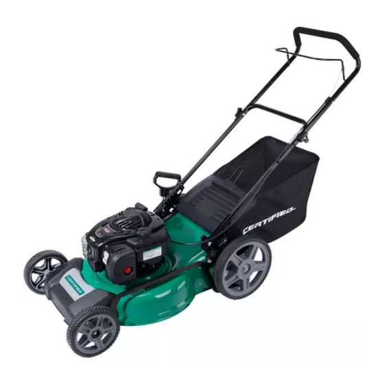
GAS-POWERED LAWN MOWER
PETROL LAWN MOWER
TONDEUSE À ESSENCE
INSTRUCTION
MANUAL
INSTRUCTION
GUIDE
MANUAL
D'UTILISATION
Advertisement
Chapters

Related Manuals for CERTIFIED 060-0190-2


Summary of Contents for CERTIFIED 060-0190-2
- Page 1 GT5658 model number / numéro de modèle : 060-0190-2 GAS-POWERED LAWN MOWER PETROL LAWN MOWER TONDEUSE À ESSENCE English version... Page 2 French version... Page 32 INSTRUCTION IMPORTANT: IMPORTANT: MANUAL Please read this manual carefully before running this gas-powered lawn INSTRUCTION mower and save it for reference.
- Page 2 For problems or questions, DO NOT RETURN TO STORE. Please contact one of our Customer Service Agents who would be happy to assist you. En cas de problèmes ou si vous avez des questions, NE RETOURNEZ PAS L’ARTICLE AU MAGASIN. Contactez plutôt un de nos agents du service à...
-
Page 3: Table Of Contents
GT5658 model no. 060-0190-2 contact us: 1-844-428-7277 TABLE OF CONTENTS Technical Specifications Parts List Intended Use Safety Information Assembly Adjustment Operation Storing and Maintenance Troubleshooting Exploded View Warranty SAVE THESE INSTRUCTIONS SAVE THESE INSTRUCTIONS This manual contains important safety and operating instructions. Read all instructions This manual contains important safety and operating instructions. -
Page 4: Technical Specifications
TECHNICAL SPECIFICATIONS Engine type Single cylinder 4-stroke Engine displacement 140 cc Engine max. power 2.2 kW/3600 RPM Engine speed 3200 RPM Cutting path 20" (51 cm) Grass bag capacity 60 L Torque 4.15-4.97 ft. lb. Height adjustments 1 1/4 to 3 3/4” (3.1 to 9.5 cm) Front wheel diameter 8”... - Page 5 054-8289-8 model no. 060-0190-2 contact us: 1-844-428-7277 KNOW YOUR LAWN MOWER SAFETY GUIDELINES • Keep children and bystanders away while operating a power tool. Distractions KNOW YOUR TOOL can cause you to lose control. To operate this tool, carefully read this...
-
Page 6: Parts List
PARTS LIST PERSONAL SAFETY POWER TOOL USE AND CARE • Stay alert, watch what you are • Do not force the power tool. Use doing and use common sense when the correct power tool for your operating a power tool. Do not use application. -
Page 7: Intended Use
054-8289-8 model no. 060-0190-2 contact us: 1-844-428-7277 INTENDED USE SERVICE min ..Minutes ..Alternating current • Have your power tool serviced by a This gas-powered lawnmower has been designed for cutting lawn areas in private house and qualified repair person using only ... -
Page 8: Safety Information
SAFETY INFORMATION PACKAGE CONTENTS: Jigsaw, wood-cutting blade, hex key, vacuum adaptor and instruction manual. IMPORTANT Look behind while backing..KEY PARTS DIAGRAM Please read these instructions fully before assembling and operating..Steep slope hazard. Description of Symbols ..Severing of toes or fingers –... -
Page 9: Safety Instructions
054-8289-8 model no. 060-0190-2 contact us: 1-844-428-7277 ASSEMBLY INSTRUCTIONS Safety instructions Do not operate machine without the entire grass catcher, discharge guard, INSTALLING THE SAW BLADE (Fig. 1) rear guard, or other safety protective Safe Practices for Pedestrian-controlled Fig. - Page 10 ADJUSTING THE BASE PLATE FOR BEVEL Watch for holes, ruts, bumps, rocks, or Never refuel the machine indoors. Fig. 2 Plate Guide Roller other hidden objects. Uneven terrain Never store the machine or fuel CUTTING (Fig. 2) could cause a slip and fall accident. Tall container where there is an open flame, 1.
-
Page 11: Maintenance And Storage
model no. 0600190 contact us: 1-844-428-7277 If you strike a foreign object, stop and Replace worn or damaged parts for inspect the machine. Repair, if safety. necessary, before starting. If the fuel tank has to be drained, this Never make any adjustments or repairs should be done outdoors. -
Page 12: Assembly
ASSEMBLY Assembling the wheels Fig. 3 As shown in Figs. 3 and 4. Loosen the nut and gasket, ensuring the corrugated gasket be well assembled on the axle, then install the wheel and fasten the nut tightly. Install the other wheel in the same way. Fig. - Page 13 054-8289-8 model no. 060-0190-2 contact us: 1-844-428-7277 OPERATION INSTRUCTIONS Assembling the handle As shown in Figs. 5 and 6. TURNING ON AND OFF (Fig. 4) Fig. 5 Fig. 4 On/off Trigger Lock-on Switch Button 1. Connect the power cord of your jigsaw to a Fasten the lower handle to the device by standard household power outlet.
- Page 14 STRAIGHT CUTTING (Fig. 6) Attaching the grass bag to the mower Fig. 6 As shown in Fig. 8. Mark the cut. Position the saw so that the Fig. 8 blade is in line with the desired cut. Mark the Lift the ejector flap with one hand position of the side edge of the saw base and grass bag and hook in the grass bag.
- Page 15 054-8289-8 model no. 060-0190-2 contact us: 1-844-428-7277 METAL CUTTING Checking and filling engine oil When cutting metal, always clamp down the material. Be careful to move the saw along slowly. Use lower speeds. Do not twist, bend, or force the blade. If the saw jumps or As shown in Figs.
- Page 16 MAINTAINANCE Remove the dipstick and check the oil Fig. 12 level: the oil level must be between the BEFORE EACH USE Min and Max marks on the dipstick. If near the lower level, fill to upper lever with 1. Inspect the jigsaw, the trigger switch, the cord and the accessories for damage. the recommended oil (SAE30 or equivalent).
- Page 17 054-8289-8 model no. 060-0190-2 contact us: 1-844-428-7277 TROUBLESHOOTING Filling with engine fuel As shown in Fig. 14. Problem Possible Causes Solution CAUTION! Always use clean, fresh unleaded gas. Purchase fuel in quantities that can be The tool is not connetced to Connect the tool to a power The motor does not start.
-
Page 18: Adjustment
ADJUSTMENT Setting the cutting height As shown in Fig. 15. CAUTION! Adjust the cutting height only Fig. 15 When the engine is switched off and the spark plug has been pulled. The cutting height is centrally adjusted with the cutting height adjusting handle. Different cutting heights can be selected. -
Page 19: Operation
060-0190-2 contact us: 1-844-428-7277 OPERATION Start and stop the engine WARNING: the blade begins to rotate as soon as the engine is started. NOTE: do not operate the machine in enclosed or poorly-ventilated areas as the exhaust gas contains toxic substances. - Page 20 Pull the starter handle out approximately Fig. 17-1 4 to 6" (10 to 15 cm) until you feel a resistance and then start the engine with a sharp pull (see Fig. 17-1). NOTE: If the engine fails to start after three pulls, repeat the process.
- Page 21 060-0190-2 contact us: 1-844-428-7277 To clean a flooded engine NOTE: if the engine won’t start after you have pressed the starter several times, the engine may be flooded with excess fuel. Use following procedure to clear and start a flooded engine.
-
Page 22: Emptying The Grass Bag
Select your required cutting height. Start the engine and allow it run, and set it to required speed. See “to start the engine”. Keep a firm grip on the upper handle with engine stop/start lever and drive lever (clutch lever) closed and walk along with it self-propelling to start mowing. Working tips Walk, never run with the mower, and be very careful when mowing uneven or rough ground. -
Page 23: Storing And Maintenance
060-0190-2 contact us: 1-844-428-7277 STORING AND MAINTENANCE WARNING: Before performing any maintenance or cleaning work, switch off the engine and wait until the blade has come to a stop. Cleaning General cleaning The lawnmower should be cleaned thoroughly every time after it has been used. -
Page 24: Changing The Engine Oil
Maintenance of the air filter As shown in Fig. 22. Soiled air filters reduce the engine output by supply too little air to the carburetor. If the air contains a lot of dust, the air filter should be checked more frequently. WARNING!Never run the engine without the air filter element installed. -
Page 25: Replacing The Blade
060-0190-2 contact us: 1-844-428-7277 Replacing the blade For safety reasons you should only ever have your blade sharpened, balanced and mounted by an authorised service workshop. For optimum results it is recommended that the blade be inspected once a year. -
Page 26: Maintenance Schedule
Storing the lawnmower for short periods The lawnmower can be stored for short periods of time (less than 15 days) without performing any storage maintenance. Before placing the lawnmower into storage always carry out the following: Allow the engine to fully cool. Ensure the grass bag is empty. - Page 27 060-0190-2 contact us: 1-844-428-7277 12 hours of use 24 hours of use 36 hours of use Air filter Clean Clean Replace Spark plug Check Clean Replace Engine oil Check Replace Check The engine oil should be changed after the first 8 hours.
-
Page 28: Troubleshooting
TROUBLESHOOTING WARNING: Before performing any maintenance or cleaning work, switch off the engine and wait until the blade has come to a stop. Caution! Improper repairs can result in the product functioning unsafely. This endangers yourself and your environment. Faults which cannot be rectified with the aid of following table may be rectified by a specialist company only (customer service centre). - Page 29 060-0190-2 contact us: 1-844-428-7277 Fault/malfunction Cause Remedy Loud while running, Screws are loose. Tighten screws. machine vibrates heavily. Blade fasteners are loose. Tighten blade fasteners. Blade is unbalanced. Replace blade. Start/stop lever not Press start/stop lever. Engine does not start.
-
Page 30: Exploded View
EXPLODED VIEW... - Page 31 060-0190-2 contact us: 1-844-428-7277 Description Description soft grip rear wheel switch bar corrugated gasket φ12 upper handle plastic shaft bush clutch cable rear shaft acorn nut M6 spring hook bolt M6X35 self-locking nut M6 nut M8 connecting rod...
-
Page 32: Warranty
2-YEARS LIMITED WARRANTY This CERTIFIED product is guaranteed for a period of 2 years from the date of original retail purchase against defects in workmanship and materials. Subject to the conditions and limitations described below, this product, if returned to... - Page 33 060-0190-2 contact us: 1-844-428-7277 Additional Limitations This warranty applies only to the original purchaser and may not be transferred. Neither the retailer nor the manufacturer shall be liable for any other expense, loss or damage, including, without limitation, any indirect, incidental, consequential or exemplary damages arising in connection with the sale, use or inability to use this product.
- Page 35 GT5658 N° de modèle : 060-0190-2 Nous joindre : 1 844 428-7277 TABLE DES MATIÈRES Fiche technique Liste des pièces Utilisation prévue Consignes de sécurité Assemblage Réglage Utilisation Entreposage et entretien Dépannage Vue éclatée Garantie SAVE THESE INSTRUCTIONS CONSERVEZ CES CONSIGNES This manual contains important safety and operating instructions.
-
Page 36: Fiche Technique
FICHE TECHNIQUE Type de moteur Cylindre unique à quatre temps Cylindrée du moteur 140 cm Puissance max. du moteur 2,2 kW / 3 600 tr/min Vitesse du moteur 3 200 tr/min Trajectoire de coupe 20 po (51 cm) Capacité du sac à herbe 60 L Couple 4,15 à... - Page 37 054-8289-8 N° de modèle : 060-0190-2 Nous joindre : 1 844 428-7277 DÉCOUVREZ VOTRE TONDEUSE À GAZON SAFETY GUIDELINES • Keep children and bystanders away while operating a power tool. Distractions KNOW YOUR TOOL can cause you to lose control.
-
Page 38: Liste Des Pièces
LISTE DES PIÈCES PERSONAL SAFETY POWER TOOL USE AND CARE • Stay alert, watch what you are • Do not force the power tool. Use doing and use common sense when the correct power tool for your operating a power tool. Do not use application. -
Page 39: Utilisation Prévue
054-8289-8 N° de modèle : 060-0190-2 Nous joindre : 1 844 428-7277 UTILISATION PRÉVUE SERVICE min ..Minutes ..Alternating current • Have your power tool serviced by a Cette tondeuse à gazon à essence a été conçue pour tondre le gazon dans les maisons et jardins qualified repair person using only ... -
Page 40: Consignes De Sécurité
CONSIGNES DE SÉCURITÉ PACKAGE CONTENTS: Jigsaw, wood-cutting blade, hex key, vacuum adaptor and instruction manual..IMPORTANT N’ouvrez pas les écrans protecteurs et ne les KEY PARTS DIAGRAM Veuillez lire ces consignes au complet retirez pas lorsque le avant d’assembler et d’utiliser la moteur est en marche. - Page 41 054-8289-8 N° de modèle : 060-0190-2 Nous joindre : 1 844 428-7277 ASSEMBLY INSTRUCTIONS Consignes de sécurité Ne projetez jamais le déchargement vers quelqu'un. Évitez de projeter des INSTALLING THE SAW BLADE (Fig. 1) matériaux sur un mur ou une obstruction.
- Page 42 ADJUSTING THE BASE PLATE FOR BEVEL par le fabricant. d'utiliser la tondeuse. Fig. 2 Plate Guide Roller Redoublez de vigilance lorsque vous CUTTING (Fig. 2) II. UTILISATION EN PENTE approchez les angles morts, les buissons, 1. Use the hex key to loosen the two hex Les pentes sont l'une des causes principales les arbres et les autres objets qui screws located on the underside of the tool.
- Page 43 054-8289-8 N° de modèle : 060-0190-2 Nous joindre : 1 844 428-7277 OPERATION INSTRUCTIONS de masse pour éviter tout démarrage l'essence dans un bidon au lieu d'utiliser la pompe à essence. involontaire. Tenez la pompe à essence sur le rebord Débranchez toujours les tondeuses...
- Page 44 STRAIGHT CUTTING (Fig. 6) Pour votre sécurité, remplacez les pièces Fig. 6 usées ou endommagées. Mark the cut. Position the saw so that the Si le réservoir de carburant doit être vidé, blade is in line with the desired cut. Mark the vous devriez le faire à...
-
Page 45: Assemblage
N° de modèle : 060-0190-2 Nous joindre : 1-844-428-7277 ASSEMBLAGE Assembler les roues Fig. 3 Comme illustré dans les figures 3 et 4. Desserrez l'écrou et le joint, en vous assurant que le joint ondulé est bien monté sur l'essieu, puis installez la roue et serrez fermement l'écrou. - Page 46 Assemblage de la poignée Comme illustré dans les figures 5 et 6. Fig. 5 boutons Fixez la poignée inférieure à l’appareil avec de réglage deux boulons à tête ronde et deux poignées guide-câble en forme d'étoile de chaque côté. Dépliez la poignée supérieure et fixez-la à...
- Page 47 054-8289-8 N° de modèle : 060-0190-2 Nous joindre : 1 844 428-7277 Attachement du sac à herbe à la tondeuse METAL CUTTING Comme illustré dans la figure 8. When cutting metal, always clamp down the material. Be careful to move the saw along Fig.
- Page 48 MAINTAINANCE Vérification de l'huile-moteur et remplissage Comme illustré dans les figures 11 à 13. BEFORE EACH USE ATTENTION! Les procédures et les réglages 1. Inspect the jigsaw, the trigger switch, the cord and the accessories for damage. goulotte de remplissage de l’huile-moteur Fig.
- Page 49 054-8289-8 N° de modèle : 060-0190-2 Nous joindre : 1 844 428-7277 TROUBLESHOOTING Insérez la jauge et vérifiez le niveau d’huile: Fig. 12 le niveau d’huile doit être compris entre les Problem Possible Causes Solution repères min. et max. sur la jauge. Si le niveau se rapproche du niveau inférieur, remplissez...
- Page 50 AVERTISSEMENT! Faites le plein dans un endroit bien ventilé et lorsque le moteur est arrêté. Ne fumez pas et ne permettez pas la présence de toute flamme ou de toute étincelle dans l’endroit où vous faites le plein du moteur ou où l’essence est entreposée. Évitez le contact prolongé...
-
Page 51: Réglage
N° de modèle : 060-0190-2 Nous joindre : 1 844 428-7277 RÉGLAGE Réglage de la hauteur de la coupe Comme illustré dans la figure 15. ATTENTION! Réglez uniquement la hauteur Fig. 15 de coupe une fois le moteur éteint et la bougie d'allumage retirée. -
Page 52: Utilisation
UTILISATION Mise en marche et arrêt du moteur AVERTISSEMENT : La lame commence à tourner dès que le moteur est mis en marche. REMARQUE : N’utilisez pas la machine dans un endroit clos ou mal ventilé, car le gaz d’échappement contient des substances toxiques. Tenez les mains, pieds, cheveux et vêtements loin de toute partie mobile de la machine. - Page 53 N° de modèle : 060-0190-2 Nous joindre : 1 844 428-7277 Tirez la poignée du démarreur d’environ 4 à Fig. 17-1 6 po (10 à 15 cm) jusqu’à ce que vous ressentez une résistance, puis mettez en marche le moteur en tirant fermement (voir figure 17-1).
- Page 54 Pour nettoyer un moteur noyé REMARQUE : Si le moteur ne démarre pas après que vous ayez actionné le démarreur plusieurs fois, il se pourrait que le moteur se soit noyé dans un excédent de carburant. Suivez la procédure qui suit pour nettoyer et mettre en marche un moteur noyé. Relâchez la commande de démarrage / d'arrêt pour arrêter le moteur.
- Page 55 N° de modèle : 060-0190-2 Nous joindre : 1 844 428-7277 AVERTISSEMENT : N’ouvrez jamais le volet d’éjection lorsque le sac à herbe a été détaché (pour vidage) et que le moteur est toujours en marche. Les lames mobiles peuvent provoquer de graves blessures! Sélectionnez la hauteur de la coupe requise.
- Page 56 Pour retirer le sac à herbe, utilisez une main pour soulever le volet d’éjection et l'autre main pour tenir la poignée de transport. Le volet d’éjection tombe automatiquement une fois le sac à herbe retiré et ferme l'ouverture de la conduite arrière. 2.
-
Page 57: Entreposage Et Entretien
N° de modèle : 060-0190-2 Nous joindre : 1 844 428-7277 ENTREPOSAGE ET ENTRETIEN REMARQUE : Avant d'effectuer toute opération d’entretien ou de nettoyage, fermez le moteur et attendez que la lame s’immobilise. Nettoyage Nettoyage général La tondeuse à gazon devrait être nettoyée après chaque utilisation. - Page 58 Entretien du filtre à air Comme illustré dans la figure 22. Les filtres à air sales réduisent le rendement-moteur en transmettant trop peu d'air au carbura- teur. Si l'air contient beaucoup de poussière, le filtre à air devrait être vérifié plus régulièrement. AVERTISSEMENT! Ne mettez jamais le moteur en marche sans que l’élément de filtre à...
-
Page 59: Remplacement De La Lame
N° de modèle : 060-0190-2 Nous joindre : 1 844 428-7277 Remplacement de la lame Pour des raisons de sécurité, vous devriez faire affûter, équilibrer et monter votre lame par un atelier de service agréé uniquement. Pour des résultats optimaux, il est recommandé de faire inspecter la lame une fois par année. - Page 60 Placez une nouvelle lame ou réaffûtez la lame. Placez la lame sur les deux goujons sur le flasque de la lame, et ensuite replacez la rondelle et les boulons. Assurez-vous que la lame soit bien en place, et ensuite serrez fermement les boulons (force de serrage de 40 à 45 Nm). Ne serrez pas trop.
- Page 61 N° de modèle : 060-0190-2 Nous joindre : 1 844 428-7277 Programme d'entretien Effectuer correctement l’entretien périodique sur votre tondeuse à gazon vous assurera une utilisation sans problème pendant nombreuses années. Veuillez conserver soigneusement ce guide pour consultation ultérieure. Il est recommandé de suivre le programme d'entretien suivant. Cela vous assurera un fonctionne- ment adéquat et une utilisation sécuritaire de la tondeuse à...
-
Page 62: Dépannage
DÉPANNAGE REMARQUE : Avant d'effectuer toute opération d’entretien ou de nettoyage, fermez le moteur et attendez que la lame s’immobilise. Attention! Des réparations non conformes peuvent amener le produit à fonctionner de manière non sécuritaire. Cela met en danger vous-même et votre environnement. Il se pourrait que l’intervention d’une entreprise spécialisée (centre de service à... - Page 63 N° de modèle : 060-0190-2 Nous joindre : 1 844 428-7277 Défaut / Défaillance Cause Solution Fonctionnement bruyant, Les boulons sont desserrés. Serrez les vis. la tondeuse vibre Le matériel de fixation de la Resserrez le matériel de beaucoup. lame est desserré.
-
Page 64: Vue Éclatée
VUE ÉCLATÉE... - Page 65 N° de modèle : 060-0190-2 Nous joindre : 1 844 428-7277 N° Description N° Description poignée souple roue arrière barre d’interrupteur joint ondulé φ12 poignée supérieure bague d'arbre en plastique câble d'embrayage arbre arrière écrou borgne M6 mousqueton boulon M6X35 écrou auto-bloquant M6...
-
Page 66: Garantie
GARANTIE LIMITÉE DE 2 ANS Le présent article de marque CERTIFIED est visé par une garantie d’une durée de 2 ans à compter de la date d’achat au détail initial en cas de vice de fabrication ou de matériaux. Assujetti aux conditions et restrictions décries ci-dessous, ce produit, s'il nous est retourné... - Page 67 N° de modèle : 060-0190-2 Nous joindre : 1 844 428-7277 Restrictions supplémentaires La garantie s'applique uniquement à l'acheteur original et n'est pas transférable. Le détaillant et le fabricant ne seront responsables de tout autre coût, perte ou dommage, y compris, sans toutefois s'y limiter, les dommages indirects, imprévus, consécutifs...
Need help?
Do you have a question about the 060-0190-2 and is the answer not in the manual?
Questions and answers
Which replacement blade do I need for a Certified Gas powered lawnmower, 060-0190-2
The replacement blade for the Certified gas-powered lawnmower model 060-0190-2 should be a new blade if the current one is cracked, damaged, excessively worn, pitted, or blunt. The exact part number or specifications for the replacement blade are not provided in the context.
This answer is automatically generated
Changing the blade - should the arrows (on the bottom) be facing down towards ground or up towards machine?