Advertisement
Table of Contents
- 1 Table of Contents
- 2 Warning Decal Placement
- 3 Important Precautions
- 4 Before You Begin
- 5 Part Identification Chart
- 6 Assembly
- 7 How to Use the Studio Cycle
- 8 Fcc Information
- 9 Maintenance and Troubleshooting
- 10 Exercise Guidelines
- 11 Part List
- 12 Exploded Drawing
- 13 Ordering Replacement Parts
- 14 Limited Warranty
- Download this manual
nordictrack.com
USER'S MANUAL
Model No. NTEX02117.0
Serial No.
Write the serial number in the space
above for reference.
Serial Number
Decal
ACTIVATE YOUR
WARRANTY
To register your product and
activate your warranty today,
go to my.nordictrack.com.
CUSTOMER CARE
For service at any time, go to
nordictrackservice.com.
Or call 1-800-TO-BE-FIT
(1-800-862-3348)
Mon.–Fri. 6 a.m.–6 p.m. MT
Sat. 8 a.m.–12 p.m. MT
Please do not contact the store.
CAUTION
Read all precautions and
instructions in this manual before
using this equipment. Keep this
manual for future reference.
Advertisement
Table of Contents

Subscribe to Our Youtube Channel
Related Manuals for NordicTrack NTEX02117.0


Summary of Contents for NordicTrack NTEX02117.0
- Page 1 USER’S MANUAL Model No. NTEX02117.0 Serial No. Write the serial number in the space above for reference. Serial Number Decal ACTIVATE YOUR WARRANTY To register your product and activate your warranty today, go to my.nordictrack.com. CUSTOMER CARE For service at any time, go to nordictrackservice.com.
-
Page 2: Table Of Contents
Apply the decal in the location shown. Note: The decal(s) may not be shown at actual size. NORDICTRACK and IFIT are registered trademarks of ICON Health & Fitness, Inc. The BLUETOOTH word ® mark and logos are registered trademarks of Bluetooth SIG, Inc. and are used under license. Google Maps is a trademark of Google LLC. -
Page 3: Important Precautions
IMPORTANT PRECAUTIONS WARNING: To reduce the risk of burns, fire, electric shock, or injury to persons, read all important precautions and instructions in this manual and all warnings on your studio cycle before using your studio cycle. ICON assumes no responsibility for personal injury or property damage sustained by or through the use of this product. - Page 4 15. The studio cycle should not be used by flywheel stops. Reduce your pedaling speed persons weighing more than 350 lbs. in a controlled way. (159 kg). 19. To stop the flywheel quickly, press the brake 16. Be careful when mounting and dismounting knob downward.
- Page 5 STANDARD SERVICE PLANS...
-
Page 6: Before You Begin
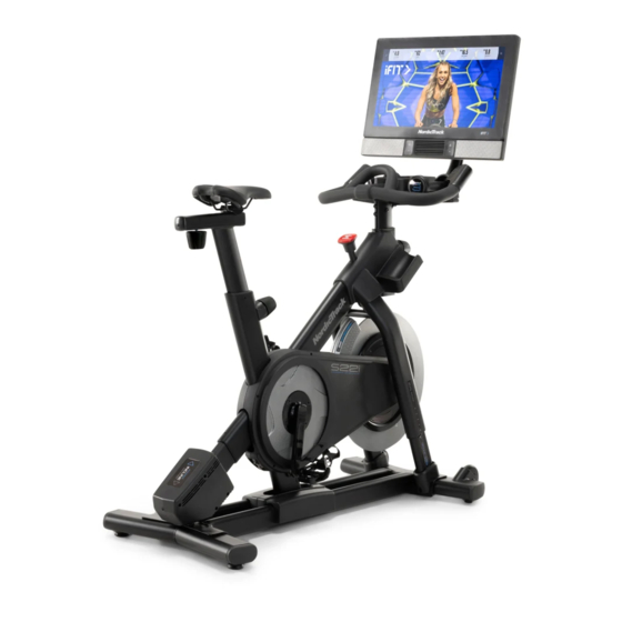
BEFORE YOU BEGIN Congratulations for selecting the revolutionary For your benefit, read this manual carefully before you use the studio cycle. If you have questions after NORDICTRACK COMMERCIAL S22I STUDIO ® CYCLE. The COMMERCIAL S22I STUDIO CYCLE is reading this manual, please see the front cover of this unlike any ordinary exercise bike. -
Page 7: Part Identification Chart
PART IDENTIFICATION CHART Use the drawings below to identify the small parts needed for assembly. The number in parentheses below each drawing is the key number of the part, from the PART LIST near the end of this manual. The number following the key number is the quantity needed for assembly. -
Page 8: Assembly
• To avoid damaging parts, do not use power tools. Assembly may be easier if you have a set of wrenches. 1. Go to my.nordictrack.com on your computer and register your product. • documents your ownership • activates your warranty •... - Page 9 3. Attach the Front Stabilizer (3) to the Base (2) with two M10 x 20mm Screws (105). 4. See the inset drawing. Orient the Handlebar Post (7) so that the lower slot (A) is on the side shown. Next, loosen the indicated Post Knob (100) and insert the Handlebar Post (7) into the Frame (1) until the lower end of the Handlebar Post is below the Frame.
- Page 10 5. Insert the Handlebar (97) into the Handlebar Post (7). Attach the Handlebar with four M8 x 12mm Screws (93); start all the Screws, and then tighten them. 6. Tip: Avoid pinching the wires (C). Slide the Console Support (8) onto the Handlebar (97). Attach the Console Support (8) with an M10 x 52mm Bolt (94) and an M10 Jam Nut (95);...
- Page 11 7. Look under the Console Support (8) and identify the Upper Wire (123), which has a larger con- nector than the Extension Wire (124). Connect the Upper Wire (123) to the Lower Wire (122) extending from the Handlebar Post (7). Then, insert the connectors on both Wires into the Handlebar Post.
- Page 12 9. Have a second person hold the Console (10) near the Console Bracket (11). Plug the Upper Wire (123) and the Extension Wire (124) into the receptacles on the back of the Console (10); make sure to plug the Wire marked with red into the receptacle marked with red, and plug the Wire marked with yel- low into the receptacle marked with yellow.
- Page 13 11. Orient the Saddle Post (13) as shown. Loosen the indicated Post Knob (100). Next, insert the Saddle Post (13) into the Frame (1), and slide the Saddle Post to the desired height. Then, tighten the Post Knob. 12. Note: You can attach your own saddle if desired.
- Page 14 13. Note: You can attach your own pedals if desired. Identify the right Pedal (56). Using an adjustable wrench, firmly tighten the right Pedal clock- wise into the Right Crank Arm (19). Firmly tighten the left Pedal (not shown) counterclockwise into the Left Crank Arm (not shown).
-
Page 15: How To Use The Studio Cycle
HOW TO USE THE STUDIO CYCLE HOW TO PLUG IN THE POWER CORD A temporary adapter may 2-pole Receptacle This product must be grounded. If it should mal- be used to function or break down, grounding provides a path of connect the Adapter least resistance for electric current to reduce the risk... - Page 16 FEATURES OF THE STUDIO CYCLE HOW TO ADJUST THE GEOMETRY OF THE STUDIO CYCLE Measuring Watts The studio cycle can be adjusted to match the geom- Each studio cycle is calibrated to measure your power etry of your road bike to promote correct form and to output and to allow you to monitor your watts and ensure proper training of the muscles.
- Page 17 How to Adjust the Saddle Post HOW TO LEVEL THE STUDIO CYCLE For effective training, the saddle should be at the If the studio cycle proper height. As you pedal, there should be a slight rocks slightly on bend in your knees when the pedals are in the lowest your floor during position.
- Page 18 CONSOLE DIAGRAM FEATURES OF THE CONSOLE When you use the manual mode of the console, you can change the resistance of the pedals and the incline The advanced console offers an array of features of the frame with the touch of a button. designed to make your workouts more effective and enjoyable.
- Page 19 HOW TO TURN ON THE POWER HOW TO USE THE TOUCH SCREEN IMPORTANT: If the studio cycle has been exposed The console features a tablet with a full-color touch to cold temperatures, allow it to warm to room tem- screen. The following information will help you use the perature before you turn on the power.
- Page 20 HOW TO SET UP THE CONSOLE 5. Check for firmware updates. Before you use the studio cycle for the first time, set up First, touch the profile button, touch Settings, touch Maintenance, and then touch Update. The the console. console will check for firmware updates. For more 1.
- Page 21 HOW TO USE THE MANUAL MODE If desired, adjust the volume level by pressing the volume increase and decrease buttons on the right 1. Touch the screen or press any button on the side of the console. console to turn on the console. To pause the workout, simply touch the screen See HOW TO TURN ON THE POWER on or stop pedaling.
- Page 22 HOW TO USE A MAP WORKOUT OR AN ONBOARD To draw your own map for a workout, see HOW TO WORKOUT CREATE A DRAW-YOUR-OWN-MAP WORKOUT on page 23. 1. Touch the screen or press any button on the console to turn on the console. When you select a workout, the screen will show an overview of the workout that includes details See HOW TO TURN ON THE POWER on...
- Page 23 HOW TO CREATE A DRAW-YOUR-OWN-MAP If the resistance level and/or incline level is too high or too low, you can manually override the setting WORKOUT by pressing the Resistance buttons or the Incline/ Decline buttons. If you press a Resistance but- 1.
- Page 24 4. Save your workout. HOW TO USE AN IFIT WORKOUT Touch Save New Workout to save your workout. If To use an iFit workout, the console must be connected desired, enter a title and description for your work- to a wireless network (see HOW TO CONNECT TO A out.
- Page 25 4. Select an iFit workout that you have previously HOW TO CHANGE CONSOLE SETTINGS added to your schedule on iFit.com. IMPORTANT: Some of the settings and features IMPORTANT: Before iFit workouts will load, you described may not be enabled. Occasionally, a must add them to your schedule on iFit.com firmware update may cause your console to function (see step 1).
- Page 26 3. View the console tour presentation. The screen will show the progress of the update. When the update is complete, the studio cycle will To view a tour presentation that will guide you turn off and then turn back on. If it does not, press through the features of the console, touch How It the power switch into the off position.
- Page 27 HOW TO CONNECT TO A WIRELESS NETWORK Follow the prompts on the screen to enter your password and connect to the selected wireless To use iFit workouts and to use several other features network. (To use the keyboard, see HOW TO USE of the console, the console must be connected to a THE TOUCH SCREEN on page 19.) wireless network.
-
Page 28: Fcc Information
HOW TO CONNECT AN HDMI CABLE enable you to continuously To show your console screen on a TV or monitor, plug monitor your an HDMI cable (not included) into the port on the con- heart rate while sole and into a port on your TV or monitor; make sure you exercise, that the HDMI cable is fully plugged in. -
Page 29: Maintenance And Troubleshooting
MAINTENANCE AND TROUBLESHOOTING MAINTENANCE HOW TO ADJUST THE LEFT CRANK ARM Regular maintenance is important for optimal If the Left Crank Arm (21) feels loose while you are performance and to reduce wear. Inspect and properly pedaling, tighten the two M6 x 25mm Screws (96). tighten all parts each time the studio cycle is used. - Page 30 Next, remove all of the Screws (not shown) attach- Remove the indicated M4 x 16mm Screw (83) and the ing the Right and Left Shields (30, 32); make sure Shield Cover (31) from each side of the studio cycle. to remember where the two shortest Screws are located.
-
Page 31: Exercise Guidelines
EXERCISE GUIDELINES Aerobic Exercise—If your goal is to strengthen your WARNING: cardiovascular system, you must perform aerobic Before beginning this exercise, which is activity that requires large amounts or any exercise program, consult your physi- of oxygen for prolonged periods of time. For aerobic cian. -
Page 32: Part List
PART LIST Model No. NTEX02117.0 R0118B Key No. Qty. Description Key No. Qty. Description Frame Resistance Disc Base Lower Saddle Clamp Front Stabilizer Upper Saddle Clamp Rear Stabilizer Saddle M6 Shoulder Screw Anchored Zip Tie Pivot Clamp Pedal Set Handlebar Post... - Page 33 Key No. Qty. Description Key No. Qty. Description Carriage Knob M5 x 8mm Screw M4 x 12mm Machine Screw M3 x 8mm Screw M4 x 10mm Screw Adjustment Block M10 Clamp Screw M4 x 10mm Blunt Screw M10 x 20mm Screw M3 x 20mm Screw M8 x 85mm Bolt Plastic Spacer...
-
Page 34: Exploded Drawing
EXPLODED DRAWING A Model No. NTEX02117.0 R0118B 34 83... - Page 35 EXPLODED DRAWING B Model No. NTEX02117.0 R0118B...
-
Page 36: Ordering Replacement Parts
ORDERING REPLACEMENT PARTS To order replacement parts, please see the front cover of this manual. To help us assist you, be prepared to provide the following information when contacting us: • the model number and serial number of the product (see the front cover of this manual) •...
Need help?
Do you have a question about the NTEX02117.0 and is the answer not in the manual?
Questions and answers