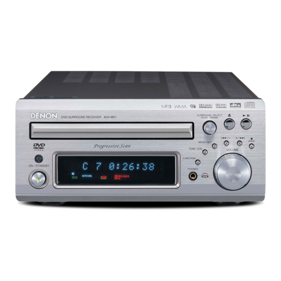
Denon ADV-M51 Service Manual
Dvd surround receiver
Hide thumbs
Also See for ADV-M51:
- Operating instructions manual (110 pages) ,
- Specification sheet (2 pages) ,
- Operating instructions manual (116 pages)
Table of Contents
Advertisement
This service manual is composed of only pages whose
contents are different from those for the model ADV-M71.
For servicing, refer to the previously issued service manual
of ADV-M71 (X0182) at the same time
●
For purposes of improvement, specifications and
design are subject to change without notice.
●
Please use this service manual with referring to
the operating instructions without fail.
●
Some illustrations using in this service manual are
slightly different from the actual set.
SERVICE MANUAL
MODEL
DVD SURROUND RECEIVER
ADV-M51
本書の内容は、既発行のサービスマニュアル ADV-M71
との相違部分のみ記載しています。
サービスの際はADV-M71(X0182)と本書をご用意
願います。
注 意
サービスをおこなう前に、このサービスマニュアルを
必ずお読みください。本機は、火災、感電、けがなど
に対する安全性を確保するために、さまざまな配慮を
おこなっており、また法的には「電気用品安全法」に
もとづき、所定の許可を得て製造されております。
従ってサービスをおこなう際は、これらの安全性が維
持されるよう、このサービスマニュアルに記載されて
いる注意事項を必ずお守りください。
● 本機の仕様は性能改良のため、予告なく変更すること
があります。
● 補修用性能部品の保有期間は、製造打切後 8年です。
●
修理の際は、必ず取扱説明書を参照の上、作業を行って
ください。
● 本文中に使用しているイラストは、説明の都合上現物
と多少異なる場合があります。
TOKYO, JAPAN
For U.S.A.,Canada,Europe,
U.K., & Japan model
Ver. 2
,
X0204 V.02 DE/CDM 0409
Advertisement
Table of Contents

Related Manuals for Denon ADV-M51


Summary of Contents for Denon ADV-M51
-
Page 1: Service Manual
For U.S.A.,Canada,Europe, U.K., & Japan model Ver. 2 SERVICE MANUAL ADV-M51 MODEL DVD SURROUND RECEIVER 本書の内容は、既発行のサービスマニュアル ADV-M71 This service manual is composed of only pages whose との相違部分のみ記載しています。 contents are different from those for the model ADV-M71. サービスの際はADV-M71(X0182)と本書をご用意 For servicing, refer to the previously issued service manual of ADV-M71 (X0182) at the same time 願います。... -
Page 2: Laser Radiation
ADV-M51 SAFETY PRECAUTIONS The following check should be performed for the continued protection of the customer and service technician. LEAKAGE CURRENT CHECK Before returning the unit to the customer, make sure you make either (1) a leakage current check or (2) a line to chassis resistance check. -
Page 3: Note For Parts List
ADV-M51 NOTE FOR PARTS LIST Part indicated with the mark " " are not always in stock and possibly to take a long period of time for supplying, or in some case supplying of part may be refused. When ordering of part, clearly indicate "1" and "I" (i) to avoid mis- supplying. -
Page 4: Parts List Of P.w.b. Unit Ass'y
ADV-M51 PARTS LIST OF P.W.B. UNIT ASS'Y Note: The symbols in the column ”Remarks” indicate the following destinations. 1U-3617 MAIN UNIT ASS’Y JP : Japan model E3 : U.S.A. & Canada model E2 : Europe model EK : U.K. model Ref.No. - Page 5 ADV-M51 Ref.No. Part No. Part Name Remarks TR503 00D 943 0091 305 F.E.T 2SK771-5 HVT2SK771-5 TR504 00D 943 0091 305 F.E.T 2SK771-5 HVT2SK771-5 TR505 00D 943 0072 201 TR KRC107S HVTKRC107S TR506 00D 943 0038 009 TR KRA102S HVTKRA102S TR507...
- Page 6 ADV-M51 Ref.No. Part No. Part Name Remarks CAPACITORS GROUP C102 00D 943 0082 709 CAP, HCUS1H102KB HCUS1H102KB C103 00D 943 0044 103 CAP, HCUS1H103KC HCUS1H103KC C104 00D 943 0044 103 CAP, HCUS1H103KC HCUS1H103KC C105 00D 943 0082 806 CAP, HCUS1H104ZF...
- Page 7 ADV-M51 Ref.No. Part No. Part Name Remarks C310 00D 943 0064 109 RES , CHIP CRJ10DJ0R0T CRJ10DJ0R0T C311 00D 943 0082 806 CAP, HCUS1H104ZF HCUS1H104ZF C312 00D 943 0078 807 CAP,ELECT HCEA1AH101T HCEA1AH101T C313 00D 943 0082 806 CAP, HCUS1H104ZF...
- Page 8 ADV-M51 Ref.No. Part No. Part Name Remarks C546 00D 943 0078 904 CAP,ELECT HCEA1AH331T HCEA1AH331T C547 00D 943 0078 807 CAP,ELECT HCEA1AH101T HCEA1AH101T C548 00D 943 0082 602 CAP, HCUS1E104KC HCUS1E104KC C549 00D 943 0082 602 CAP, HCUS1E104KC HCUS1E104KC C550...
- Page 9 ADV-M51 Ref.No. Part No. Part Name Remarks C718 00D 943 0083 407 CAP, HCUS1H390JA HCUS1H390JA C719 00D 943 0083 407 CAP, HCUS1H390JA HCUS1H390JA C720 00D 943 0082 709 CAP, HCUS1H102KB HCUS1H102KB C721 00D 943 0082 806 CAP, HCUS1H104ZF HCUS1H104ZF C722...
- Page 10 ADV-M51 Ref.No. Part No. Part Name Remarks C798 00D 943 0083 300 CAP, HCUS1H332KC HCUS1H332KC C799 00D 943 0083 300 CAP, HCUS1H332KC HCUS1H332KC C800 00D 943 0083 009 CAP, HCUS1H152KC HCUS1H152KC C803 00D 943 0083 300 CAP, HCUS1H332KC HCUS1H332KC C804...
- Page 11 ADV-M51 Ref.No. Part No. Part Name Remarks X301 00D 943 0075 305 CERAMIC , RESONATOR BVFCSTLS16M0X51 X501 00D 943 0085 609 CRYSTAL HOX04332E160C For E2,EK X701 00D 943 0085 706 CRYSTAL(HC-49/U03) HOX12288E242C 00D 943 0070 902 SPACER , FL CHG1A284...
- Page 12 ADV-M51 1U-3528/3585 AMP/POWER UNIT ASS’Y Note: The symbols in the column ”Remarks” indicate the following destinations. JP : Japan model E3 : U.S.A. & Canada model E2 : Europe model EK : U.K. model Ref.No. Part No. Part Name Remarks...
- Page 13 ADV-M51 Ref.No. Part No. Part Name Remarks D201 00D 943 0041 708 DIODE HVD1SS355T HVD1SS355T D401 00D 943 0041 708 DIODE HVD1SS355T HVD1SS355T D402 00D 943 0041 708 DIODE HVD1SS355T HVD1SS355T D403 00D 943 0041 708 DIODE HVD1SS355T HVD1SS355T D404...
- Page 14 ADV-M51 Ref.No. Part No. Part Name Remarks R801 00D 943 0074 801 RES,CARBON BRDERC12UGK335T BRDERC12UGK225T For E3 R802 00D 943 0092 508 RES,METAL(OXIDE)FILM KRG1SANJ4R7RT KRG1SANJ4R7RT R803 00D 943 0093 002 RES,FUSE KRQ12AJ681RT KRQ12AJ681RT R901 RC05GF2H225K(UL) R902 00D 943 0092 100...
- Page 15 ADV-M51 Ref.No. Part No. Part Name Remarks C421 00D 943 0082 204 CAP,METALLIZED FILM HCME1H104JT HCME1H104JT C422 00D 943 0082 602 CAP, HCUS1E104KC HCUS1E104KC C423 00D 943 0082 602 CAP, HCUS1E104KC HCUS1E104KC C424 00D 943 0082 408 CAP,MYLAR HCQI1H103JZT HCQI1H103JZT...
- Page 16 ADV-M51 Ref.No. Part No. Part Name Remarks C929 00D 943 0079 408 CAP,ELECT HCEA1CLXZ471 HCEA1CLXZ471 C930 00D 943 0079 408 CAP,ELECT HCEA1CLXZ471 HCEA1CLXZ471 C931 00D 943 0079 408 CAP,ELECT HCEA1CLXZ471 HCEA1CLXZ471 C932 00D 943 0082 107 CAP,CERAMIC HCKD3D681KP HCKD3D681KP For E2,EK...
- Page 17 ADV-M51 Ref.No. Part No. Part Name Remarks FB208 00D 943 0074 704 EMI FILTER BLZ92001Z For E2,EK FF901 00D 943 0036 904 HOLDER , FUSE KJCFC5S FF902 00D 943 0036 904 HOLDER , FUSE KJCFC5S FF903 00D 943 0036 904...
-
Page 18: Parts List
ADV-M51 EXPLODED VIEW Parts List 109 104 2 -5 2 -4 1 -2 1 -1 2 -1 2 -3 2 -2 1 -3... -
Page 19: Parts List Of Exploded View
ADV-M51 Note: The symbols in the column ”Remarks” indicate PARTS LIST OF EXPLODED VIEW the following destinations. JP : Japan model E3 : U.S.A. & Canada model E2 : Europe model EK : U.K. model Ref.No. Part No. Part Name... - Page 20 PANEL , FRONT(AL) CKM1A153YC39 For E3 00D 144 2893 007 PANEL , FRONT(AL) CKM1A153ZC39 For JP 00D 131 0156 106 BADGE , DENON CGB1A140Z 00D 102 0664 108 CABINET , TOP CKC1A157S27 00D 146 2362 000 PANEL , LOADER CGR1A347RED3...
-
Page 21: Packing View
ADV-M51 PACKING VIEW Note: The symbols in the column ”Remarks” indicate ∼ the following destinations. JP : Japan model E3 : U.S.A. & Canada model E2 : Europe model EK : U.K. model PARTS LIST OF PACKING & ACCESSORIES Ref.No. -
Page 22: Note For Schematic Diagram
ADV-M51 NOTE FOR SCHEMATIC DIAGRAM 配線図について 1. WARNING: 印の部品は安全を維持するために重要な部品です。 Parts marked with this symbol have critical character- 従って交換時は必ず指定の部品を使用してください。 istics. Use ONLY replacement parts recommended by the manu- facturer. 注) 2. CAUTION: 1. 指定なき抵抗値は Ω、k は kΩ、M は MΩ を示 Before returning the unit to the customer, make sure you す。... - Page 23 ADV-M51 SCHEMATIC DIAGRAMS (1/15) DISPLAY UNIT SCHEMATIC DIAGRAMS (1/15) 1U-3617-3 DISPLAY UNIT (For ALL MODEL)
- Page 24 ADV-M51 SCHEMATIC DIAGRAMS (2/15) AUDIO-DIR/DAC UNIT SCHEMATIC DIAGRAMS (2/15) 1U-3617-1 AUDIO UNIT (1/3) DIR/DAC Section (For ALL MODEL)
- Page 25 ADV-M51 SCHEMATIC DIAGRAMS (3/15) AUDIO-VOLUME UNIT SCHEMATIC DIAGRAMS (3/15) 1U-3617-1 AUDIO UNIT (2/3) VOLUME Section (For E3/JAPAN MODEL)
- Page 26 ADV-M51 SCHEMATIC DIAGRAMS (4/15) AUDIO-VOLUME UNIT SCHEMATIC DIAGRAMS (4/15) 1U-3617-1 AUDIO UNIT (2/3) VOLUME Section (For E2/EK MODEL)
- Page 27 ADV-M51 SCHEMATIC DIAGRAMS (5/15) AUDIO- COM UNIT SCHEMATIC DIAGRAMS (5/15) 1U-3617-1 AUDIO UNIT (3/3) COM Section (For JAPAN MODEL)
- Page 28 ADV-M51 SCHEMATIC DIAGRAMS (6/15) AUDIO- COM UNIT SCHEMATIC DIAGRAMS (6/15) 1U-3617-1 AUDIO UNIT (3/3) COM Section (For E3 MODEL)
- Page 29 ADV-M51 SCHEMATIC DIAGRAMS (7/15) AUDIO- COM UNIT SCHEMATIC DIAGRAMS (7/15) 1U-3617-1 AUDIO UNIT (3/3) COM Section (For E2/EK MODEL)
- Page 30 ADV-M51 SCHEMATIC DIAGRAMS (8/15) PIN JACK UNIT SCHEMATIC DIAGRAMS (8/15) 1U-3617-2 PIN JACK UNIT (For E3/JAPAN MODEL)
- Page 31 ADV-M51 SCHEMATIC DIAGRAMS (9/15) PIN JACK UNIT SCHEMATIC DIAGRAMS (9/15) 1U-3617-2 PIN JACK UNIT (For E2/EK MODEL)
- Page 32 ADV-M51 SCHEMATIC DIAGRAMS (10/15) POWER UNIT SCHEMATIC DIAGRAMS (10/15) 1U-3528-2 POWER UNIT (For JAPAN MODEL)
- Page 33 ADV-M51 SCHEMATIC DIAGRAMS (11/15) POWER UNIT SCHEMATIC DIAGRAMS (11/15) 1U-3528-2 POWER UNIT (For E3 MODEL)
- Page 34 ADV-M51 SCHEMATIC DIAGRAMS (12/15) POWER UNIT SCHEMATIC DIAGRAMS (12/15) 1U-3585-2 POWER UNIT (For E2/EK MODEL)
- Page 35 ADV-M51 SCHEMATIC DIAGRAMS (13/15) AMP/VIDEO,POSISTER,SP TERMINAL UNIT SCHEMATIC DIAGRAMS (13/15) 1U-3528-1 AMP/VIDEO UNIT 1U-3528-3 POSISTER UNIT 1U-3528-4 SP TERMINAL UNIT (For JAPAN MODEL)
- Page 36 ADV-M51 SCHEMATIC DIAGRAMS (14/15) AMP/VIDEO,POSISTOR,SP TERMINAL UNIT SCHEMATIC DIAGRAMS (14/15) 1U-3528-1 AMP/VIDEO UNIT 1U-3528-3 POSISTOR UNIT 1U-3528-4 SP TERMINAL UNIT (For E3 MODEL)
- Page 37 ADV-M51 SCHEMATIC DIAGRAMS (15/15) AMP/VIDEO,POSISTER,SP TERMINAL UNIT SCHEMATIC DIAGRAMS (15/15) 1U-3585-1 AMP/VIDEO UNIT 1U-3585-3 POSISTOR UNIT 1U-3585-4 SP TERMINAL UNIT (For E2/EK MODEL)
Need help?
Do you have a question about the ADV-M51 and is the answer not in the manual?
Questions and answers