
Related Manuals for Carel VFD-NXL


Summary of Contents for Carel VFD-NXL
-
Page 1: User Manual
VFD - NXL NXL family User manual I n t e g r a t e d C o n t r o l S o l u t i o n s & E n e r g y S a v i n g s... - Page 3 Follow the commissioning instructions, see Chapter 7 “Commissioning“ page 37. The CAREL VFD-NXL Frequency Converter is now ready for use. In the end of this manual, you will fi nd a quick help with the default I/O, control panel menus, monitoring values, fault codes and basic parameters.
-
Page 5: Table Of Contents
10. DESCRIPTION OF EXPANDER BOARD OPTAI 41 11. FLANGE MOUNTING KIT FOR NXS/P FREQUENCY CONVERTERS FR4FR6 11.1 General ........................42 11.2 CAREL fl ange mounting kit contents ..........42 11.3 Installation ......................43 11.4 Information Sticker ..................44 VFD-NXL +030220721 - rel. 2.2 - 10.05.2011... -
Page 7: Safety
The motor terminals U, V, W (T1, T2, T3) and the DC-link/brake resistor terminals ¬–/+ (in CAREL VFD-NXL ≥1.1 kW) are live when CAREL VFD-NXL is connected to mains, even if the motor 1.4 Running the motor is not running. - Page 8 Manufacturer’s declaration of conformity The following page presents the photocopy of the Manufacturer’s Declaration of Conformity assuring the compliance of frequency converters with the EMC-directives. VFD-NXL +030220721 - rel. 2.2 - 10.05.2011...
-
Page 9: Receipt Of Delivery
In normal conditions, CAREL VFD-NXL frequency converters are maintenance-free. However, we recommend to clean the heatsink (using e.g. a small brush) whenever necessary. Most CAREL VFD-NXL drives are equipped with a cooling fan, which can easily be changed if necessary. VFD-NXL +030220721 - rel. 2.2 - 10.05.2011... -
Page 10: Technical Data
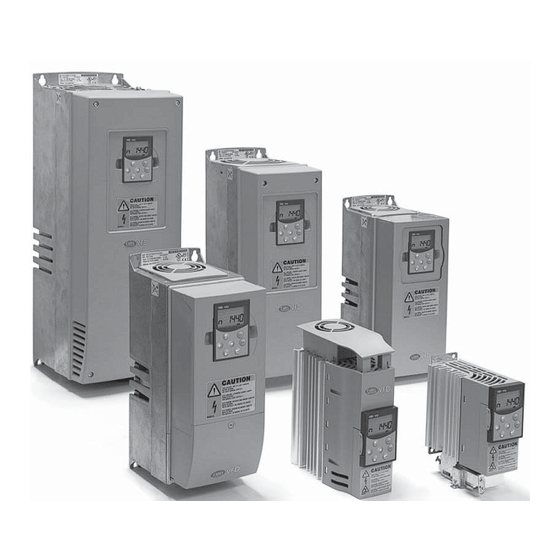
CAREL VFD-NXL is a compact frequency converter with the output ranging from 250 W to 30 kW. You can have your CAREL VFD-NXL drive equipped with control I/O boards OPT-AA, OPT-AI, OPT-B_ or OPT-C_. In CAREL VFD-NXL frequency converter the internal microprocessor controls the motor basing on the information it receives through All other sizes but MF2 have an internal brake chopper. -
Page 11: Power Ratings
3.2 Power ratings CAREL VFD-NXL – Mains voltage 208 – 240 V Mains voltage 208-240 V, 50/60 Hz, 1~/3~ Series NXL Loadability Motor shaft power Mechanical size Frequency High High Nominal input Dimensions Weight Enclosure and Rated continuous 10% overload... -
Page 12: Technical Data
In case of earth fault in motor or motor cable, only the frequency converter is protected Unit overtemperature protection Motor overload protection Protections Motor stall protection Motor underload protection Short-circuit protection of +24 V and +10 V reference voltages Overcurrent protection Trip limit 4,0*IH instantaneously Tab. 3.c VFD-NXL +030220721 - rel. 2.2 - 10.05.2011... -
Page 13: Installation
MF2 with a filter MF2 without a filter Fig. 4.a Fig. 4.b 4.2 Dimensions Ø H2 H3 nxlk7.fh8 Fig. 4.c Dimensions (mm) Type W1 W2 H1 Ø 60 172 152 140 130 80 150 144 VFD-NXL +030220721 - rel. 2.2 - 10.05.2011... - Page 14 128 100 327 313 292 190 7 3 x 28.3 Ø fr5ip21.fh8 144 100 419 406 391 214 7 2 x 37 1 x 28.3 195 148 558 541 519 237 9 3 x 37 Fig. 4.e VFD-NXL +030220721 - rel. 2.2 - 10.05.2011...
-
Page 15: Cooling
4.4 Changing EMC protection class from H to T Forced air fl ow cooling is used for frames MF4, MF5, MF6 and higher The EMC protection class of CAREL VFD-NXL frequency converter types powers of MF3. Enough free space shall be left above and below the MF4 –... -
Page 16: Cabling And Connections
Tab. 5.c Note: The earth leakage current of NXL exceeds 3.5mA a.c. According to EN61800-5-1, a reinforced protective ground connection must be ensured. See paragraph 1.3 “Earthing and earth fault protection“ page 7. VFD-NXL +030220721 - rel. 2.2 - 10.05.2011... - Page 17 Mounting of cable accessories Enclosed to your CAREL VFD-NXL frequency converter you have received a plastic bag containing components that are needed for the installation of the mains and motor cables in the frequency converter. Fig. 5.c.b Fig. 5.b Components: Ref.1...
- Page 18 Installation of cables to CAREL VFD-NXL Note: In case you want to connect an external brake resistor (MF3 and bigger sizes), see separate Brake Resistor Manual. Control cable Earth terminal Motor cable Mains cable Fig. 5.e.a Fig. 5.e.b VFD-NXL +030220721 - rel. 2.2 - 10.05.2011...
- Page 19 Installation of an external RFI fi lter to MF2 and MF3 The EMC protection class of CAREL VFD-NXL frequency converters MF2 and MF3 can be changed from N to H with an optional external RFI fi lter.
- Page 20 Fig. 5.i.b Note for MF4: Two protective conductors are required for MF4 according to EN61800-5-1. See paragraph 1.3 “Earthing and earth fault protection“ page 7 and fi gure 6.r. Fig. 5.j.a Fig. 5.j.b VFD-NXL +030220721 - rel. 2.2 - 10.05.2011...
- Page 21 Earth terminals Motor cable Mains cable Fig. 5.l.a Fig. 5.l.b Note for MF6: Reinforced protective ground connection must be ensured according to standard EN61800-5-1. See paragraph 1.3 “Earthing and earth fault protection“ page 7. VFD-NXL +030220721 - rel. 2.2 - 10.05.2011...
-
Page 22: Control Unit
+60/75°C must be used. The tightening torques of the terminals are given in the following table. The control unit of the CAREL VFD-NXL frequency converter is integrated with the power unit and consists roughly of the control board and one... - Page 23 Control power supply backup RO1/1 Relay output 1 Switching capacity: 24 Vdc/8 A RO1/2 250 Vac/8 A 125 Vdc/0,4 A RO1/3 Relay output terminals are galvanically isolated from the I/O ground Tab. 5.h VFD-NXL +030220721 - rel. 2.2 - 10.05.2011...
- Page 24 Motor thermistor (PTC) connection 0 .. .2 0 mA ; C urrent input There are three possibilities to connect a PTC resistor to CAREL VFD-NXL: With optional board OPT-AI. (Recommended method) CAREL VFD-NXL equipped with OPT-AI fulfi lls IEC 664 if the motor Volta g e inp ut;...
-
Page 25: Control Keypad
The control keypad is the link between the CAREL frequency converter 6.2 Keypad push-buttons and the user. The CAREL VFD-NXL control keypad features a seven- The CAREL seven-segment control keypad features 7 push-buttons that segment display with seven indicators for the Run status (RUN,... -
Page 26: Start-Up Wizard
6.3 Start-up wizard CAREL VFD-NXL has a built-in start-up wizard, that speeds up the programming of the drive. The wizard helps you choose between four diff erent operating modes, Standard, Fan, Pump and High Performance. Each mode has automatic parameter settings optimised for the mode in question. - Page 27 6.e. The values are updated once every 0.3 seconds. Fig. 6.f This menu is meant only for value checking. The values cannot be altered here. For changing values of parameters see paragrafo “Monitoring value” page 38. VFD-NXL +030220721 - rel. 2.2 - 10.05.2011...
- Page 28 37. You will fi nd the complete paremeter lists and descriptions in the Just set the new desired value with the Browser buttons and confi rm +030220726 manual (that can be download from website www.carel. the change with the Enter button. Consequently, the blinking stops com).
- Page 29 See Table 6.h. Fault types. I/O te r m S TO P I /O te r m S TO P I /O te r m n xl k1 9. fh8 Fig. 6.i VFD-NXL +030220721 - rel. 2.2 - 10.05.2011...
- Page 30 The data connection between the fi eldbus Master and the Check installation. Fieldbus fault fi eldbus board is broken If installation is correct contact the nearest CAREL distributor Slot fault Defective option board or slot Check board and slot.; Contact the nearest CAREL distributor...
- Page 31 Note! the submenus are not showing if no option board is installed I6.8.6.2.1 Slot D Status 1=Connection lost; 2=Initializing; 3=Run; 5=Fault I6.8.6.2.2 Slot D Program version S6.9 AI mode P6.9.1 AIA1 mode 0=Voltage input; 1=Current input (Types MF4 – MF6) VFD-NXL +030220721 - rel. 2.2 - 10.05.2011...
- Page 32 STOP I/O term I/O term The CAREL NX frequency converter features a possibility for the user to store and load two customised parameter sets (all parameters included in the application, not the system menu parameters) and to load back the factory default parameter values.
- Page 33 Use the Browser buttons to change the fan. the Enter button or return to the previous level with the Menu button left. See Fig. 6.m - for how to change the HMI acknowledgement timeout. VFD-NXL +030220721 - rel. 2.2 - 10.05.2011...
- Page 34 I/O term STOP I/O t erm READY READY STOP I/O term STOP I/O t erm Fig. 6.q enter Fig. 6.p When you want to reset the operation counters, you should do Example: the following: VFD-NXL +030220721 - rel. 2.2 - 10.05.2011...
- Page 35 The ID numbers can be found in the parameter tables. When several parameters/monitoring values are read at a time they must be consecutive. 11 addresses can be read and the addresses can be parameters or monitoring values. VFD-NXL +030220721 - rel. 2.2 - 10.05.2011...
- Page 36 0 = 300 baud 1 = 600 baud 2 = 1200 baud 3 = 2400 baud 4 = 4800 baud 5 = 9600 baud 6 = 19200 baud 7 = 38400 baud 8 = 57600 baud VFD-NXL +030220721 - rel. 2.2 - 10.05.2011...
-
Page 37: Commissioning
Change the frequency reference (potentiometer) converter (except for the galvanically isolated I/O terminals) are live when CAREL VFD-NXL is connected to mains potential. Check in the Monitoring menù (M1) that the value of Output Coming into contact with this voltage is extremely dangerous frequency changes according to the change of frequency and may cause death or severe injury. - Page 38 Preset speed 2 0,00 Par. 2.1.2 50,00 P2.1.21 Automatic restart 731 0= Not used; 1=Used 0= All parameters and menus visible; 1=Only group P2.1 and P2.1.22 Parameter conceal menus M1 – H5 visible Tab. 7.c VFD-NXL +030220721 - rel. 2.2 - 10.05.2011...
-
Page 39: Fault Tracing
Check keypad connection and possible keypad cable. frequency converter is broken. Check installation. The data connection between the fi eldbus Master and Fieldbus fault If installation is correct contact the nearest CAREL the fi eldbus board is broken distributor. Slot fault Defective option board or slot Check board and slot. -
Page 40: Description Of Expander Board OptAa
9. DESCRIPTION OF EXPANDER BOARD OPTAA Note: check the Carel price list, to verify if the options are available. Fig. 9.a Description: I/O expander board with one relay output, one open collector output and three digital inputs. Allowed slots: CAREL VFD-NXL board slot E... -
Page 41: Description Of Expander Board OptAi
Note: per la disponibilità delle opzioni previste, consultare il listino CAREL. Fig. 10.a Description: I/O expander board with one relay output (NO), three digital inputs and one thermistor input for CAREL VFD- NXL frequency converters Allowed slots: CAREL VFD-NXL board slot E Type ID:... -
Page 42: Flange Mounting Kit For Nxs/P Frequency Converters Fr4Fr6
11.1 General 11.2 CAREL fl ange mounting kit contents Using the CAREL Flange Mounting Kit, you can mount your CAREL NX The contents of the Flange Mounting Kits for diff erent frames are shown frequency converter through the cabinet wall so that the control unit of in the following pictures. -
Page 43: Installation
#6 (red) and #7 (black) of the basic set aside at step 10b. accurately. Do not slam, do not picture and use the ties (#5) to fi x I/O board (NXOPTA1 or NXOPTA8)* force! the cables on the power unit. VFD-NXL +030220721 - rel. 2.2 - 10.05.2011... -
Page 44: Information Sticker
-25 °C…100 °C@25 °C -25 °C…100 °C@25 °C -25 °C…100 °C@25 °C -25 °C…100 °C@25 °C -25 °C…100 °C@25 °C Dimension Fig. 1 Fig. 2 Fig. 3 Fig. 1 Fig. 4 Tab. 11.b VFD-NXL +030220721 - rel. 2.2 - 10.05.2011... - Page 45 NXARF13200 Ø6 (4 pcs) M5x0.8 - 6 (5 pcs) Wires 4x1.5 mm 60 ±5 7 ±1 load Ferrule N, L 7 ±1 140.5 30 ±5 187 ±15 Fig. 11.i Code NXARF12200 Fig. 11.j VFD-NXL +030220721 - rel. 2.2 - 10.05.2011...
- Page 46 CAREL is a registered trademark of CAREL Industries in Italy and/or other countries. © CAREL Industries 2008 all rights reserved CAREL reserves the right to modify the features of its products without prior notice. VFD-NXL +030220721 - rel. 2.2 - 10.05.2011...
- Page 48 Agenzia / Agency: CAREL INDUSTRIES HQs Via dell’Industria, 11 - 35020 Brugine - Padova (Italy) Tel. (+39) 0499 716611 - Fax (+39) 0499 716600 carel@carel.com - www.carel.com...
Need help?
Do you have a question about the VFD-NXL and is the answer not in the manual?
Questions and answers