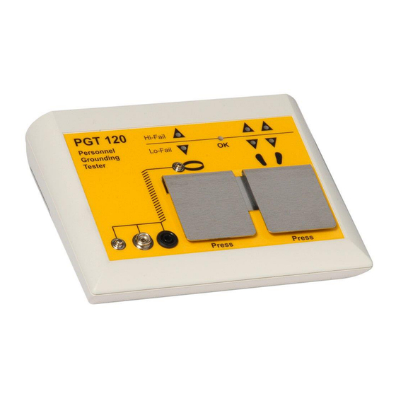
Summary of Contents for Wolfgang Warmbier PGT 120
- Page 1 ® Personnel Grounding Tester Wrist Strap and Footwear Tester Users's Manual...
-
Page 2: Table Of Contents
PGT120 Art.Nr. 7100.PGT120 1 Table of contents TABLE OF CONTENTS ..................2 INTRODUCTION ....................3 Device return and environmentally compatible disposal ......3 INSTALLATION ....................4 OPERATION ......................5 Wrist strap test ....................5 Coil cord test ....................5 Footwear test (single shoe) ................6 Wrist strap and footwear test ................ -
Page 3: Introduction
PGT120 Art.Nr. 7100.PGT120 2 Introduction ® The Personnel Grounding Tester PGT 120 is an electronic test instrument for checking personnel grounding systems such as wrist straps, coil cords and footwear. ® The PGT 120 is suitable for compliance verification of the above products, according to the IEC 61340-5-1 Edition 1.0 (2007-08) or ANSI/ESD S 20.20 –... -
Page 4: Installation
PGT120 Art.Nr. 7100.PGT120 3 Installation The Unit is for desktop or wall mounting. The optionally available wall mounting frame (Part No. 7100.PGT120.WK) can be used to fix the unit to a wall. The power is either supplied by a 9V battery or by a power supply. Insert the batteries by opening the battery compartment flap on the bottom side of the unit. -
Page 5: Operation
PGT120 Art.Nr. 7100.PGT120 4 Operation This tester has no power switch. Pressing an electrode or activating "footwear in series" activates the electrical circuit. The measuring voltage is preset to 100V. Use the DIP switches 6+7 to adjust the voltage to either 30V or 50V. 4.1 Wrist strap test ... -
Page 6: Footwear Test (Single Shoe)
PGT120 Art.Nr. 7100.PGT120 4.3 Footwear test (single shoe) Settings: Only footwear or OR is activated (DIP switch 1+2) Stand on the foot electrode, then press the right electrode and keep it pressed. A peep signal indicates the start of measurement. After a short measuring time the result is displayed. -
Page 7: Footwear In Series
PGT120 Art.Nr. 7100.PGT120 4.5 Footwear in series Settings: Footwear in series activated (DIP switch 8) To show that "Footwear in series" is activated the red LED's for Hi-Fail of Footwear flash for a short time every 2s, while disspative shoes are not detected. The footwear test can be accomplished hands free, without touching a electrode. -
Page 8: Configuration
PGT120 Art.Nr. 7100.PGT120 5 Configuration The unit can be configured with the DIP switches on the rear according to the table below. Standard settings are marked bold. Switch 1 Switch 2 Test mode "OR" (wrist strap or footwear test) Only footwear test Only wrist strap test "AND"... -
Page 9: Connectors
PGT120 Art.Nr. 7100.PGT120 6 Connectors The connectors for the power supply, the foot electrodeand the door opener are located on the rear side of the unit. Use a "RJ12" western modular plug to connect the dry contact of the door opener. The door opener relay is triggered and stays on for 3 seconds when the test result indicates OK. -
Page 10: Wall Mounting Instructions
PGT120 Art.Nr. 7100.PGT120 7 Wall mounting instructions (Part No. 7100. PGT120.WK) Fix the wall mounting plate with the supplied dowels and screws and stick the self- adhesive Velcro tapes according to the picture. ® 1. The surface of the plate and the bottom side of the PGT 120 have to be clean, dry and free of grease. -
Page 11: Specifications
PGT120 Art.Nr. 7100.PGT120 8 Specifications Operating voltage: 9V E 6F22 battery external power supply 230V / 50Hz Operating conditions: 15 ... 40°C up to 75% relative humidity, non condensing Storage conditions: -10 ... 60°C up to 85% relative humidity, non condensing Connectors: Wrist strap 10mm snap, 4mm snap, 4mm... -
Page 12: Pictures
PGT120 Art.Nr. 7100.PGT120 9 Pictures 12 / 13 2014-11-27... - Page 13 PGT120 Art.Nr. 7100.PGT120 13 / 13 2014-11-27...
- Page 14 Änderungen vorbehalten Subject to change without notice WOLFGANG WARMBIER GmbH & Co. KG Untere Gießwiesen21 D-78247 Hilzingen Telefon +49 77 31 86 88-0 Telefax +49 77 31 86 88-30 e-mail: info@warmbier.com http://warmbier.com...


Need help?
Do you have a question about the PGT 120 and is the answer not in the manual?
Questions and answers