Table of Contents
Advertisement
Advertisement
Table of Contents

Related Manuals for Express Water Alkaline RO


Summary of Contents for Express Water Alkaline RO
-
Page 1: Installation Manual
Alkaline RO System INSTALLATION MANUAL 1-800-992-8876 Customer Support... - Page 2 All material published on this site by Express Water Inc., including all portions of the website, content, site design, text, and graphics may NOT BE REPRODUCED OR DISTRIBUTED, in whole or in part, without prior written permission of Express Water Inc.
-
Page 3: Table Of Contents
Table Of Contents • Purchase introduction..................Page 4 • Included Components/Parts................. Page 5 • Itemization of Components................Page 6 • Installation STEP 1 Tighten the housings..................Page 8 • Installation STEP 2 Insert elbow fittings..................... Page 9 • Installation STEP 3 Connect to feed water line................ - Page 4 Introduction You have purchased the finest residential Reverse Osmosis Alkaline Drinking Water System available for your home. When properly maintained, this system will provide you with years of great tasting, pure drinking water and trouble-free service. Please read the enclosed section regarding the proper care and maintenance of your new Water System, and experience the taste of exceptional purity.
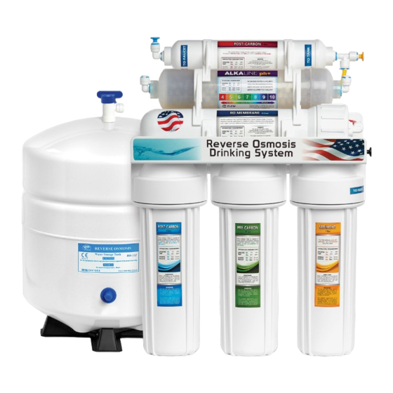
- Page 5 Components / Parts Your new RO Alkaline system should include the following items. If any item is missing, please contact your supplier, retailer or any local professional plumbing service. Please take a few moments to check all the following components: •...
- Page 7 Quick Connect Guide...
-
Page 8: Installation Step 1
Installation Step 1 Tighten The Housings BOTTOM FILTER PLACEMENT Remove plastic wrappings from the 3 housings and filters, then assemble the housings onto the main system as follows: 1. Stand the 3 housings upright. Make sure each housing has a rubber O-ring in its groove. 2. -
Page 9: Installation Step 2
Installation Step 2 Elbow Fitting Connection Screw the elbow fitting into the end of the right filter housing (in) until tightened and (the insert) is facing at a downward angle. Fully insert the white tubing into the fitting. Apply force while pushing tube into fitting to ensure the quick connect has locked. -
Page 10: Installation Step 3
Installation Step 3 Feed Water Adapter Tapping into COLD WATER line CAUTION! The water supply to the unit MUST be from the COLD WATER LINE. HOT WATER will severely damage your R.O. System. Locate the cold water (angle) shut off valve (see picture above) underneath the sink and turn it off. - Page 11 Red Tube Red Tube As shown above, this adapter connection can be used for both 3/8” or 1/2” feed line plumbing. Simply by switching the adapter nut like below (PART A) from one side of the adapter valve to the other. NOTE! DO NOT USE TEFLON TAPE (USE WRENCH)
-
Page 12: Installation Step 4
Installation Step 4 Leak Detector POSITION THE SYSTEM TO THE DESIRED POSITION THE LEAK DETECTOR IN THE PERMANENT LOCATION SAME CABINET NEAR THE SYSTEM AND SCREW IT TO THE CABINET FLOOR White Tube Red Tube CONNECT THE RED TUBE INTO THE FEED VALVE AND INTO THE INLET (IN) OF THE LEAK DETECTOR. -
Page 13: Installation Step 5
Installation Step 5 Drain Saddle Valve A Drain Saddle Valve is used to connect the waste water line to the drain pipe under the sink, and is designed to fit around a standard 1 1/2-inch OD drain pipe. The drain saddle valve should always be installed before (above) the p-trap and on a vertical or horizontal drain pipe. -
Page 14: Installation Step 6
Installation Step 6 RO Faucet (If Applied) - Page 15 The RO Faucet may be installed on any flat surface. Check the underside of the location for interference. You may use the existing hole on the sink or drill a new hole. Make sure the washer is big enough to cover the hole. If you drill a new hole on the countertop or sink, make sure that drilling the hole will not damage any pipe or wiring underneath the countertop or sink.
-
Page 16: Installation Step 7
Installation Step 7 RO Tank Assembly NOTE! Do not tamper with the air valve on low side of storage tank. It has been preset at 7–10 psi by the manufacturer. 1. Open the box and remove the stand from the top of the tank. 2. -
Page 17: System Connections
System Connections 1/4” Yellow Tubing to Tank 1/4” Blue Tubing to Faucet 1/4” Black Tubing to Drain 1/4” Red Tubing from Feed • A to B. Connect the RED tube into the feed adapter (point A) and to the inlet marked as “in”... -
Page 18: System Startup
System Startup 1. Turn on both the cold water supply and the under sink feed-water valve, but close the tank ball valve. If any leaks are noted, turn off valve and correct before proceeding. 2. Open RO faucet for continuous flow (flow rate may vary). 3. -
Page 19: System Maintenance
System Maintenance This recommendation is intended for maximum efficiency of RO SYSTEM. 1. Filter maintenance a. It is OK to store filters for several years. b. To keep the unopened filter sealed, place it into an airtight container, preventing it from absorbing air. This prolongs the shelf life of the carbon filter and avoids any possible odor from the air. -
Page 20: Filter Change Instruction
Filter Change How to change the 1st, 2nd and 3rd stage fitlers 1. Turn off the water supply connected to the Reverse Osmosis system and Tank Valve (if applicable) -- then open the dispensing tap downstream to release pressure. 2. After releasing pressure, place the filter manifold in a bucket and unscrew the filter sumps using the filter wrench to loosen the housings. - Page 21 connection to disconnect the fitting from the two ends of the filter. Discard the old filter and connect the fitting to the new post carbon filter. 4. Now you can fully open the inlet tap and the tank valve (if any) and empty the tank.
-
Page 22: Troubleshooting
Troubleshooting VACATION MODE Please Locate the red valve found on the feed water adapter connected to your water supply (shown on page 6 component 1). Activate: Turn the Red valve away from the red tube connection to shut off feed water supply to the system. -
Page 23: Conditions
Conditions READ THIS FIRST Please pay attention to the following installation and safety recommendations: • Read the installation manual before installing this system. • Install the system at a location with adequate drainage. • This water system unit is for INDOOR use ONLY. To preserve the unit, avoid using extremely HOT/COLD water, and protect against sudden temperature changes. -
Page 24: Warranty
For a period of 1 year from the date of purchase, if this Product is determined to be defective, Express Water will repair or replace the Product at no charge. After the Warranty Period, you must pay for all the charges.
Need help?
Do you have a question about the Alkaline RO and is the answer not in the manual?
Questions and answers