Rinnai E50CRN Installation & Servicing Instructions Manual
High effi ciency condensing gas boiler
Hide thumbs
Also See for E50CRN:
- User's information manual (33 pages) ,
- Installation & servicing instructions manual (180 pages)
Table of Contents
Advertisement
I n s t a l l a t i o n & S e r v i c i n g
High effi ciency condensing gas boiler
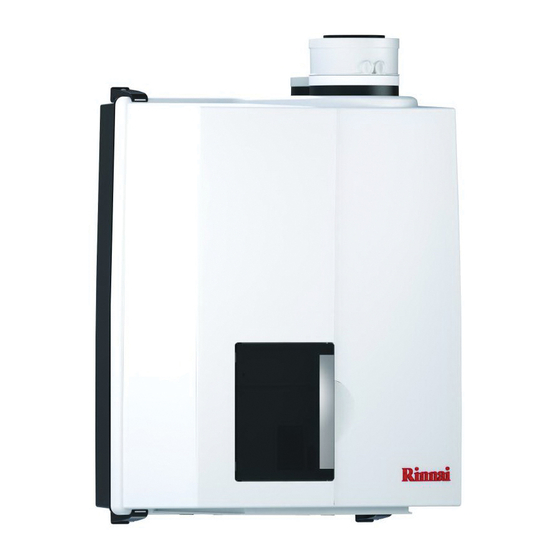
Pictured: E50CRN
E75CRN, E110CRN
E75CRP, E110CRP
WARNING!
If you do not follow these instructions exactly, a fi re or explosion
may result causing property damage, personal injury or loss of life.
Wall-hung Condensing Boilers:
E50CR, E75CR, E110CR
- Do not store or use gasoline or other fl ammable vapors and
- WHAT TO DO IF YOU SMELL GAS
Toll-free: 1-800-621-9419 • Fax: 678-829-1666 • www.rinnai.us
Instructions
E75CRN/E110CRN
E75CRP/E110CRP
CAUTION!
Read this manual thoroughly before installing, servicing, putting
into operation or using this boiler and vent system.
WARNING!
Improper
maintenance can cause property damage, personal injury
(exposure to hazardous materials) or loss of life. Refer to the
user's information manual provided with this boiler. Installation
and service must be performed by a licensed professional, service
agency or the gas supplier (who must read and follow the supplied
instructions before installing, servicing, or removing this boiler).
CAUTION!
The user manual is part of the documentation that is delivered
to the installation's operator. Go through the information in this
manual with the owner/operator and make sure that they are
familiar with all necessary operating instructions.
NOTICE!
Installation and service must be performed by a qualifi ed
installer, service technician or the gas supplier.
In the Commonwealth of Massachusetts this boiler must be
installed by a licensed Plumber or Gas Fitter.
liquids in the vicinity of this or any other appliance.
- Do NOT try to light any appliance.
- Do NOT touch any electrical switch.
- Do NOT use any phone in your building.
- Immediately call your gas supplier from a neighbor's phone.
Follow the gas supplier's instructions.
- If you cannot reach your gas supplier, call the fi re department.
Address: 103 International Drive, Peachtree City, GA, 30269
These instructions to be retained by user.
E50CRN
installation,
adjustment,
alteration,
service
or
Advertisement
Table of Contents

Related Manuals for Rinnai E50CRN


Summary of Contents for Rinnai E50CRN
- Page 1 Follow the gas supplier’s instructions. - If you cannot reach your gas supplier, call the fi re department. Address: 103 International Drive, Peachtree City, GA, 30269 Toll-free: 1-800-621-9419 • Fax: 678-829-1666 • www.rinnai.us These instructions to be retained by user.
- Page 2 Contents of instructions These installation instructions contain important information for the safe installation, start-up and maintenance of boilers with capacities 50,000 through 110,000 BTU/hr. These installation instructions are intended for licensed professionals, who have the necessary knowledge and are approved for working on heating and gas systems. Subject to technical changes Changes may be made without notice to the illustrations, process steps and technical data as a result of our policy of continuous improvement.
-
Page 3: Table Of Contents
Content Safety and general instructions ............4 Electrical connections ..............40 Designated use ..............4 Boiler controls .................44 Hazard defi nitions ..............4 Explanation of the function buttons ........45 Symbol defi nitions ...............4 Starting up: Filling and de-aerating the boiler and installation ..46 The following instructions must be followed ......5 Requirements of the water system ........46 Follow these instructions for the space heating water ..6 Filling the heating system ..........47... -
Page 4: Safety And General Instructions
Safety and general instructions Please observe these instructions in the interest of your own safety. 1.1 Designated use The boiler is designed for heating water for a central heating system and generating domestic hot water. The boiler is delivered with a burner controller (MCBA) pre- installed.The boiler can be fi... -
Page 5: The Following Instructions Must Be Followed
1.4 The following instructions must be followed The boiler must only be used for its designated purpose, as described in the Installation Instructions. Each unit is fi tted with a data plate. Consult the details on this plate to verify whether the boiler is compliant with its intended location, e.g.: gas type, power source and venting classifi... -
Page 6: Tools, Materials And Additional Equipment
– Never use water that has been treated by a reverse osmosis, deionized, or distilled water to soften the water to fi ll the heating system. – Do not use inhibitors or other additives unless approved by Rinnai for that purpose. – When freeze protection of the heating system is desired, only use Rinnai-approved antifreezes. -
Page 7: Relevant Installation, Service And User Manuals
1.7 Relevant Installation, Service and User manuals – Approved vent system – User manual 1.8 Disposal – Dispose of the boiler packaging in an environmentally sound manner. – Dispose of components of the heating system (e.g. boiler or control device), that must be replaced in an environmentally responsible manner. -
Page 8: Description Of The Boiler
NFPA 720 and be ANSI/UL 2034 listed and IAS certifi ed. Description of the boiler The Rinnai E-Series Combi boiler is a modulating condensing central heating boiler, with an integrated DHW capability. The boiler is provided with a compact stainless steel heat exchanger with smooth tubes. -
Page 9: Packaging And Transportation
The boiler is supplied ready for use. • Please check if the packaging is intact. • Check if all the items listed are included in the delivery. The supply kit contents: Description Amount E50CRN E75CRN E110CRN E75CRP E110CRP Part No. Fitting Kit complete: 804000088 804000046... -
Page 10: Installation
Installation 5.1 Requirements for installation location This boiler is intended for indoor installations only. DANGER The room where the boiler will be placed must always be free from freezing conditions. Do not store or use gasoline or other fl ammable vapors and liquids in the vicinity of this or any other appliance. -
Page 11: Mounting The Boiler
5.2 Mounting the boiler Remove the packaging materials. Lay the boiler on its back during unpacking. Remove the cover from the NOTICE boiler. This part may be left off during installation. It must be placed on the boiler and fi xed with the screw behind the door and in the 4 quick releases before the boiler is started up. -
Page 12: Dimensions
5.3 Dimensions E50CRN E75CRN E75CRP E110CRN E110CRP w g k w g k dimensions fi gure 1 dimensions table 1... -
Page 13: Clearances From Boiler
5.3.1 Clearances from boiler ceiling Min. 10" / 2" 250mm 2" 15.7" 24" service clearances to the boiler fi gure 4 Minimum required clearances Minimum required clearances Required to combustibles to non-combustibles service clearances All types All types All types inch / mm inch / mm inch / mm... -
Page 14: Technical Specifi Cations
5.4 Technical specifi cations Technical specifi cations Table 4... -
Page 15: Connecting The Boiler
Connecting the boiler The boiler has the following pipe connection; The central heating circuit pipes. The gas supply pipe. Provided with a 3/4" male thread. See further chapter 6.4; Cold and hot water pipes for domestic hot water (DHW). These consist of 3/4" MNPT x 15mm compression adapter fi ttings. See further chapter 6.5;... -
Page 16: Central Heating System
6.1 Central heating system Connect the central heating system according to its instructions. When removing the plastic sealing caps from the pipes, water may come out NOTICE of the boiler due to live fi re testing during manufacturing. The boiler, when used in connection with a refrigeration system, must be NOTICE installed so the chilled medium is piped in parallel with the boiler with appropriate valves to prevent the chilled medium from entering the boiler. - Page 17 Boiler system fl ushing (Not Boiler heat exchanger) When replacing an existing boiler the heating system shall be fl ushed with an approved system cleaner (refer to system cleaner list) before the new boiler is added to the system. If the old boiler has already been removed a bypass must be piped in when the new boiler is installed in order to facilitate the fl...
- Page 18 19. Test the water hardness of the water that will be used for fi lling the system 20. Use the proper water treatment to ensure the pH and water hardness are within the Rinnai boiler water quality guidelines 21. The boiler and system may now be fi lled.
- Page 19 For information on locating the expansion tank and system fi ll, please see the Rinnai Boiler Applications Manual. The boiler is designed to be used on pressurized heating systems only (closed NOTICE loop).
-
Page 20: Safety Valve
If these instructions are not followed exactly, a fi re or explosion may result causing property damage, personal injury or death. Rinnai wall mounted E boilers are built to run on their specifi ed gas type either Natural Gas or Liquid Propane (not for E50CRN). The gas type the boiler is... -
Page 21: Gas Connection With Natural Gas
E75CR: 804000015 E110CR: 804000016 Propane gas: resume with chapter 6.4.2 When natural gas is desired, the boiler (not for E50CRN) can be converted to natural gas by means of a conversion kit. Rinnai Part number: E75CR: 804000023 E110CR: 804000024 6.4.1... - Page 22 6.4.2 Gas connection with propane gas (not for E50CRN) The gas supply connection must comply with local regulations or, if such NOTICE regulations do not exist, with the National Fuel Gas Code, ANSI Z 223.1. Pipe sizing for propane gas Contact gas supplier to size pipes, tanks, and gas pressure regulator.
-
Page 23: Hot Water Supply
6.5.2 Domestic water treatment Accessory Rinnai off ers a domestic water treatment device that can help reduce scale build up. This device can be installed on the incoming cold water line for any combi boiler. For additional information on contact Rinnai. -
Page 24: Dhw Expansion Tank
6.5.3 DHW Expansion Tank A domestic water expansion tank could be required by local code. Check local code to determine if it is required. If a combi boiler is installed in a closed water supply system, such as one having a backfl... -
Page 25: Installing A Valve Kit
A means to isolate the domestic plate heat exchanger for cleaning must be provide at installation. Refer to fi gure 10 for proper piping layout. A Rinnai valve kit can be used on domestic water pipes for all combi boilers to allow for cleaning of the plate heat exchanger and installation the domestic hot water pressure relief valve. -
Page 26: Condensate Drain Pipe
The condensate produced by the boiler has a pH value between 3 and 4. Install a neutralization unit if required by local code. It is recommended, but not required to install a condensate neutralizer. Rinnai off ers a condensate neutralizer designed to work with all boiler models. The condensate neutralizer kit comes with all the necessary fi... -
Page 27: Vent System And Air Supply System
If it becomes necessary to access an enclosed vent system for service or NOTICE repairs, Rinnai is not responsible for any costs or diffi culties in accessing the vent system. The limited warranty does not cover obtaining access to an enclosed vent system. -
Page 28: Examples Vent And Air Supply Systems (Parallel)
6.7.2a Examples vent and air supply systems (parallel) Wall thickness for vent termination installation: Examples sealed combustions Minimum: 100mm / 4” Maximum: 508mm / 20” Horizontal with parallel termination fi gure 12B Horizontal with concentric termination fi gure 12A 10" MINIMUM INSIDE EDGE T`O INSIDE EDGE 12"... - Page 29 6.7.2b Examples vent and air supply systems (concentric) Wall thickness for vent termination installation: Examples wall terminals Minimum: 100mm / 4” Maximum: 508mm / 20” Short termination with wall terminal Termination with wall terminal on higher level fi gure 13A fi...
- Page 30 6.7.2 c Examples vent and air supply systems (PP Twin Pipe and Flex) Vertical twin pipe termination fi gure 13F Horizontal twin pipe elbow termination fi gure 13G Horizontal twin pipe concentric termination fi gure 13H Horizontal twin pipe elbow termination below grade fi...
- Page 31 Flex through chimney termination fi gure 13K Flex through B vent as a chase termination fi gure 13L...
- Page 32 6.7.2 d Boiler Exhaust Vent Hanger and Support (Rigid Pipes) The purpose of this section is to provide more information about Rinnai’s requirement that the vent system installed with the Rinnai boiler must be appropriately supported. As we state elsewhere in this manual, "place pipe supports every 4 feet (1219 mm) of horizontal run, beginning with the support near the boiler to prevent movement in fi...
-
Page 33: Installation Of The Vent System
fi tted, with or without elbow pieces. The maximum permissible pipe length is set out in table 9, chapter 6.7.6. The E50CRN boiler is provided standard initially with a parallel connection, but can be converted to a concentric system with with an optional adapter (Part nr. 808000023). - Page 34 6.7.3.1 Boiler conversion from parallel to concentric (E50CRN) 808000023 Concentric vent adapter (Part. nr. 808000023) consists of: 1. Cover air intake 2. Gasket 3" 3. Gasket 5" 4. Concentric adapter 5. Plugs for measuring points 6. Gasket 3" A. Push the 2 clips of both 3" connections slightly inwards B.
-
Page 35: Installing Air Fi Lter
6.7.3.2 Boiler conversion from concentric to parallel (E75CR/E110CR) A. 1. Push the 2 clips slightly outwards B. 2. Pull the concentric adaptor out of the boiler 3. Press the cover in the connection at the back from inside out C. 4. Push the 3" air intake connector into the connection at the back of the boiler 5. -
Page 36: Vent/Air Intake Terminal Position
6.7.4 Vent/air intake terminal position Terminals should be positioned as to avoid products of combustion entering openings into buildings or other vents. Maintain 12” of clearance above highest anticipated snow level or grade or, whichever is greater. Please refer to your local codes for the snow level in your area. - Page 37 Terminals should be positioned as to avoid products of combustion entering NOTICE openings into buildings or other vents. Maintain 12” of clearance above the highest anticipated snow level or grade CAUTION or, whichever is greater. Please refer to your local codes for the snow level in your area.
-
Page 38: Direct Vent Closet And Alcove Installation
Failure to follow this warning could result in fi re, personal injury, or death. Rinnai strongly suggests the use of PPs venting for all closet and alcove installations. For non direct vent room air applications see sections 6.7.5 and 6.7.8. -
Page 39: Dimensioning Of The Exhaust And Air Intake Duct
Failure to provide a properly installed vent and air system may cause severe personal injury or death. Use only the material listed in Rinnai's vent documentation for vent pipe, and WARNING fi ttings. Failure to comply could result in severe personal injury, death or substantial property damage. -
Page 40: Combustion Air And Vent Piping Lengths
6.7.7 Combustion air and vent piping lengths. In the table below you will fi nd the maximum equivalent pipe length of the vent/air system based on 2" and 3" diameter. These lengths are for single pipe (room air) and twin pipe and concentric venting systems. Equivalent vent length table 9 Equivalent friction loss of PVC/CPVC... -
Page 41: Calculation Of Compensation Factor
Engineering group. This is to ensure the product is installed and the overall system is designed properly and that the units are commisioned properly. Not involving of Rinnai's Engineering group would result in no support of the product and no warranty. -
Page 42: Room Air System (Indoor Combustion Air)
6.7.9 Room Air System (indoor combustion air) When using indoor air, Rinnai strongly recommends the use of an indoor air fi lter, P/N 808000025. This boiler requires adequate combustion air for ventilation and dilution of fl ue WARNING gases. Failure to provide adequate combustion air can result in unit failure, fi re, explosion, serious bodily injury or death. - Page 43 Confi ned Space: (Small Room, Closet, Alcove, Utility Room, Etc.) A confi ned space is defi ned in the NFPA #54 as "a space whose volume is less than 50 cubic feet per 1000 Btu/hr (4.8 m3 per kW per hour) of the aggregate input rating of all appliances installed in that space."...
- Page 44 Using Indoor Air For Combustion When using air from other room(s) in the building, the total volume of the room(s) must be of adequate volume (Greater than 50 cubic feet per 1000 Btu/hr). Each combustion air opening must have at least one square inch of free area for each 1000 Btuh, but not less than 100 square inches each.
-
Page 45: Electrical Connections
Electrical connections The electrical connections to the boiler must be electrically grounded in accordance with all applicable local codes and the latest revision of the National Electrical Code, ANSI/NFPA-70. Devices such as, outdoor sensor, room thermostat or temperature control, and temperature sensor or thermostat are all connected to the internal connection terminal. - Page 46 Power supply sensor Controller therm. safety 100 mA three-way valve sensor On / Off contact CH DHW N CAUTION CAUTION Terminals 4 to 11 are for Rinnai use only and not for use in any installation. Connection terminal fi gure 22...
-
Page 49: Boiler Controls
Boiler controls The boiler is provided with a fully automatic microprocessor control, called CMS Control Management System. This control simplifi es operation by undertaking all major control functions. Initially when power to the unit is switched on it will remain on standby. -
Page 50: Explanation Of The Function Buttons
8.1 Explanation of the function buttons Boiler control panel fi gure 24 Only licensed professionals who are trained for servicing these boilers are NOTICE permitted to make alterations in the controller to calibrate the boiler to the installation. 1. Display. See previous page for further information. 2. -
Page 51: Starting Up: Filling And De-Aerating The Boiler And Installation
fl ushed to remove sediment. Flush until clean water runs free of sediment. Rinnai suggests using an approved system cleaner to fl ush the system, but not the boiler. Always use Rinnai approved antifreezes. See the list at the end of this chapter. -
Page 52: Filling The Heating System
The system should be tested at least once a year and as recommended by the producer of the glycol solution. The allowed maximum concentration is 50%. Use only Rinnai approved inhibitors. See below for an approved list of inhibitors. NOTICE... -
Page 53: Hot Water Supply
13 If A XX appears on the display, wait for 17 minutes; 14 Check the water pressure and if necessary top it up to 16 to 18 PSI 15 Close the fi lling loop; 16 Press the ‘STEP’-button; 17 Be sure that the fi lling loop is closed. 18 After the automatic de-aeration program (A XX) is fi... -
Page 54: For Your Safety Read Before Operating
FOR YOUR SAFETY READ BEFORE OPERATING WARNING: If you do not follow these instructions exactly, a fi re or explosion may result causing property damage, personal injury or loss of life. A. This appliance does not have a pilot. It is equipped with an ignition device which automatically lights the burner. -
Page 55: Adjustments
CAUTION commissioning of the boiler. Read through the Parameter chapter to adjust the boiler to its installation. Contact Rinnai in case of doubt. Only licensed professionals who are trained for servicing these boilers are NOTICE permitted to make alterations in the controller to calibrate the boiler to the installation. - Page 56 DESCRIPTION 176°F maximum supply temperature CH 68 - 176°F type of CH installation: 00 - 04 No pre-selection made. Radiators, air heating, or convectors: T max. supply 176°F K factor heating curve 2.3; gradient 10°F/min; gear differential 10°F DO NOT USE radiators with large surface areas or underfloor heating as additional heating: T max.
-
Page 57: Outdoor Reset
NOTICE the adjustments which are stated in this table are unnecessary when in combination with the Rinnai RS100 thermostat and will be taken care of by the RS100 itself and do not have to be adjusted. For further information regarding to the RS100 thermostat refer to the Rinnai RS100 installation manual. -
Page 58: Activating Factory Settings (Green Button Function)
10.2 Activating factory settings (green button function) To activate the factory settings again please follow the next procedure (Note: all altered adjustments will be set back to their orignial factory settings that are accessible in the current service level the boiler is in either user or 123): Select, when necessary, the technical read out;... -
Page 59: Commissioning
3. When the impeller spins freely and water exits though the vent port the pump is ready for operation. 4. Replace the vent screw During the commissioning of the boiler the Rinnai Installation, Commissioning, and Service card must be fi lled out. Pump commissioning... -
Page 60: Testing For Gas Leaks
12.1 Testing for gas leaks Prior to start-up of the boiler you must check the external tightness of the gas supply valve and confi rm this in the start-up report. Before leak testing the boiler, ensure all parts of the boiler such as electronics WARNING and wiring are properly covered and protected from the leak testing agent. -
Page 61: Checking The O
12.3 Checking the O at full load (Step 1/3) The O percentage setting is required to be checked at commissioning, NOTICE maintenance and faults and adjusted if needed. The O percentage is required to be checked and adjusted after a conversion WARNING from NG to LP or from LP to NG. - Page 62 O value at full load. The measuring procedure must be carried out, until a constant measuring result is achieved. Please take up contact with Rinnai, if the values should lie outside of the applicable tolerances. checkpoint O fi gure 27 Switching off...
- Page 63 12.3.2 Settings on the gas valve (Step 3/3) Step 3: Adjustment on the gas valve. Only if the measured values are outside the range of the table on the previous NOTICE page. Open the boiler as described on page 59. Remove the black cover of the gas valve by unscrewing the sealed screw.
-
Page 64: Measuring The Ionization Current
12.4 Measuring the ionization current Switch off the system using the Central Heating button and the DHW button Disconnect plug socket connection probe connect measuring device series. fi gure Select the μA direct current range on the measuring device. The measuring device must have a resolution of at least 1 μA. -
Page 65: Maintenance
fi rst. When doing this the circumstances of the boiler’s location must be taken into account. From this one can determine whether to deviate from this advice. Please contact Rinnai for further guidance on the frequency and service NOTICE requirements. -
Page 66: Visual Inspection For General Signs Of Corrosion
NOTICE operating in normal circumstances. The conditions (eg. supply air quality) in which the boiler is installed should be taken into account. This will show whether the frequency of replacement should be reduced or increased. If in doubt, contact RINNAI. -
Page 67: Maintenance Activities
13.3 Maintenance activities The fan unit and burner cassette (fi gure 32 to 34) (every 4 year maintenace) Remove the electrical connection plug from the gas valve (1) and fan motor (2); Loosen the nut (3) of the gas pipe under the gas valve; Replace the gasket with a new one;... - Page 68 Use of non-Rinnai parts will result in the voiding of the limited warranty. Do not use substitute materials. Use only parts certifi ed with the appliance.
- Page 69 4. Connect drain hose (H3) to service valve (V2). 5. Pour approximately 4 gallons of virgin, food grade, white vinegar or citric acid into pail. 6. Place the drain hose (H3) and the hose (H2) to the pump (CP) inlet into the cleaning solution.
-
Page 70: Reset Service Interval Counter
Visual inspection of the fl ame (2 and 4 year maintenance) The burner must fl ame evenly over the entire surface when operating correctly. The fl ame must burn with a clear, blue, stable fl ame. Check the fl ame through the inspection glass in the ignition probe (fi g. 38). The fl... -
Page 71: Parts Of The Boiler
Parts of the boiler 12 13 Rinnai E-Series fi gure 41 1 heat exchanger 9 operating panel 17 ASME / NB / CRN data plate 2 ignition unit 10 Control Tower (CMS) 3 fan unit 11 water fi lter return CH... -
Page 72: Blocks And Errors
Blocks and Errors 15.1 Error indication (short reference) A detected error is indicated on the display by means of blocking or error messages. A distinction should be made between these two messages due to the fact that blocking can be of a temporary nature, however, error messages are fi xed lockings. The control will try its utmost to prevent locking and will temporarily switch off... -
Page 73: Blocks
Connect outdoor sensor or repair wiring (position 18/19) or replace outdoor sensor. Incorrect parameter setting for the Call Rinnai minimum or maximum power A temperature diff erence has been Check the supply and return sensor for the resistance value and replace... -
Page 74: Errors
15.3 Errors Code Description Solution Incorrect fl ame formation. boiler Check whether the ionization cable and/or the electrode are responsible for a has not been burning but an possible short-circuit. Remove the plugs from the ionization cable connected ionization fl ow (fl ame) has still to the control unit and to the electrode. - Page 75 Code Description Solution Control unit error Anticipation resistance wire not When a power stealing room stat device is placed the connection terminal present needs to be provided with the special anticipation resistance wire. Software error control unit. Software error control unit. Replace the control unit. Remove the E-Prom from the defective control unit and place it onto the new control unit .The controller will automatically load the program into the new control unit.
- Page 76 Code Description Solution No signal from the fan The fan is not running. Check the wiring to the fan and the control unit and/ or the 24 volt power supply to the fan Wiring and voltage are OK and error is repeated. Replace the fan Negative pressure on vent Check vent system.
- Page 77 Code Description Solution contact for return sensor T2 Check the data in Error mode. Boiler data during error: open 1 Error = 37 2 Operational status = 00 3 Flow temp. = xx* 4 Return temp. = -22 5 kW burner = 00** 6 % pomp = xx*...
-
Page 78: Other Errors
15.4 Other Errors Complaint Description Solution Central heating but no Switch on DHW program on the Control Tower -Key of the DHW program is domestic hot water not switched on 2. Flow switch is not working Check fl ow and/or check for impurities. Check on properly. -
Page 80: Spare Parts
Spare parts Parts casing and rear wall E-Series I n s t a l l a t i o n & S e r v i c i n g Instructions High efficiency condensing gas boiler E75CN/E110CN E75CP/E110CP CAUTION! Read this manual thoroughly before installing, servicing, putting into operation or using this boiler and vent system. - Page 81 E50CRN E75CRN E110CRN Rinnai Part Item Art. No. Description E75CRP E110CRP Number OSS1 OSS1 OSS2 S4479500 GASKET CASING E 809000073 S4479300 CASING SET 809000074 S4447200 BOILER COVER BOLT M5X20 (SET OF 5 BOLTS) 809000127 809000075 S4479400 SPRING DOOR CASING S4479100...
- Page 82 Parts heat exchanger E-Series...
- Page 83 E50CRN E75CRN E110CRN Rinnai Part Description Item Art. No. Number E75CRP E110CRP OSS1 OSS1 OSS2 809000014 30 S4310800 CLAMP BAR TOP PART H.EX. LONG 807000010 31 S4735000 TOP PART HEAT EXCH. SET OSS1 807000011 S4735100 TOP PART HEAT EXCH. SET OSS2...
- Page 84 Parts pipes E-Series 118 119 123 124 125 126 127 128 119a 119b 104 103 106 107 106a...
- Page 85 E50CRN E75CRN E110CRN Rinnai Part Description Item Art. No. Number E75CRP E110CRP OSS1 OSS1 OSS2 91 S4334500 O-RING ø21.89X2.62 GASLINE 809000061 92 S4340830 GASKET FITTING 3/4" GASV. 809000062 806000020 93 S4321900 GAS PIPE E75C 806000021 S4333800 GAS PIPE E110C 94 S4772900...
- Page 86 Parts electrical components E-Series 162 T1 supply sensor 160 T2 return sensor 167 T3 DHW sensor 166 T5 fl ue gas sensor 168 HLS high limit switch 161 P1 water pressure sensor...
- Page 87 E50CRN E75CRN E110CRN Rinnai Part Description Item Art. No. Number E75CRP E110CRP OSS1 OSS1 OSS2 805000041 140 S4768200 HARNESS E STICKER CONNECTION TERMINAL 805000046 8U352200 CONNECTOR 2-POLE PURPLE 805000015 S4320300 CONNECTOR 3-POLE GRAY 805000018 S4380900 CONNECTOR 4-POLE BROWN 805000021 S4320600...
-
Page 88: Parts List Vent System
Parts list vent system DuraVent (PolyPro) - Page 90 Vent Manufacturer Contact Information for Installation Instructions and Parts Lists: Heat-Fab Rinnai/Ubbink Telephone: 800-772-0739 Telephone: 800-621-9419 Fax: 413-863-4803 Fax: 678-829-1666 cystsvc@heat-fab.com www.rinnai.us www.heatfab.com York International IPEX Telephone: 405-364-4040 Telephone: 800-463-9572 877-874-7378 905-403-0264 www.york.com/products/unitary/ Fax: 905-403-9195 www.ipexamerica.com CENTROTHERM Eco System Telephone:...
-
Page 91: Appendix A - Outoor Reset Sensor Data And Resistance Table Ntc Sensors
Appendix A - Outoor Reset Sensor Data and Resistance table NTC sensors Temp NTC 12K R 25 °C 12 k (12k /77°F) °F R 100 ° C supply sensor T1 return sensor T2 25/85 DHW sensor T3 outside sensor T4 c i f flue gas sensor T5 98,000... - Page 92 Appendix B - Optional accessories Low Loss Header Rinnai supplies optional for each type of boiler a Low Loss Header. Find below the dimensions. 12.5” 319mm Plumbing Kit 1 2.0” 4.7” 10.2” Part. no.: 804000061 50mm 119mm 260mm Suitable for:...
- Page 93 shut off valve system circulator check valve balancing valve boiler drain valve dirt trap air separator automatic fi ll valve back fl ow preventer 10. expansion tank bypass for system cleaning Low Loss Header Service valve Service valve Boiler basic piping fi...
- Page 94 This kit provides an alternative to for installations with height limitations and allows for an alternative piping installation. Kit 1 for boiler models E50CR, E75CR and E110CR Rinnai part number: 804000071. Side mounting kit fi gure 9...
- Page 95 Appendix C - Approved system cleaners, inhibitors and antifreeze The following is a list of approved system cleaners, inhibitors, and antifreeze. Approved antifreeze: • Rhomar RhoGard Mutli-Metal (AL safe) • Sentinel X500 • Noble Noburst AL • Fernox Alphi 11 Approved system cleaner: •...
- Page 96 P e a c h t r e e C i t y , 3 0 2 6 9 Toll Free: (800) 621-9419 • Tel: (678) 829-1700 • Fax: (678) 829-1666 • E-mail: info@rinnai.us • Internet: www.rinnai.us E. & O. E.
Need help?
Do you have a question about the E50CRN and is the answer not in the manual?
Questions and answers