Yamaha RS7000 Service Manual
Music production studio
Hide thumbs
Also See for RS7000:
- Owner's manual (352 pages) ,
- Software manual (17 pages) ,
- Addendum (4 pages)
Advertisement
Table of Contents
This document is printed on chlorine free (ECF) paper with soy ink.
SY
011572
20010630-175000
MUSIC PRODUCTION STUDIO
CONTENTS
DIMENSIONS
SPECIFICATIONS
PANEL LAYOUT
CIRCUIT BOARD LAYOUT
WIRING
BLOCK DIAGRAM
DISASSEMBLY PROCEDURE
INSTALLING OPTIONAL EQUIPMENT
LSI PIN DESCRIPTION
IC BLOCK DIAGRAM
CIRCUIT BOARDS
TEST PROGRAM
ERROR MESSAGE
MIDI IMPLEMENTATION CHART ......................................... 72
OS UPDATE
PARTS LIST
OVERALL CIRCUIT DAIGRAM
SERVICE MANUAL
............................................................ 3
.............................................. 4/6
...................................... 8
............................................................. 13
................................... 32
......................................... 34
.................................... 74/75
1.498K-6451
............... 11
......................... 14
............................ 15
...... 19
.............................. 27
............................. 46/56
........................... 66/69
HAMAMATSU, JAPAN
Printed in Japan '01.07
Advertisement
Table of Contents

Related Manuals for Yamaha RS7000


Summary of Contents for Yamaha RS7000
- Page 1 MUSIC PRODUCTION STUDIO SERVICE MANUAL CONTENTS DIMENSIONS ............3 SPECIFICATIONS ..........4/6 PANEL LAYOUT ........8 CIRCUIT BOARD LAYOUT ....11 WIRING ............. 13 BLOCK DIAGRAM ......14 DISASSEMBLY PROCEDURE ......15 INSTALLING OPTIONAL EQUIPMENT ..19 LSI PIN DESCRIPTION ......
- Page 2 IMPOR TANT NOTICE This manual has been provided for the use of authorized Yamaha Retailers and their service personnel. It has been assumed that basic service procedures inherent to the industry, and more specifically Yamaha Products, are already known and under- stood by the users, and have therefore not been restated.
- Page 3 RS7000 IMPOR TANT NOTICE FOR THE UNITED KINGDOM Connecting the Plug and Co Connecting the Plug and Co Connecting the Plug and Co Connecting the Plug and Co Connecting the Plug and Cor r r r r d d d d d IMPORTANT.
-
Page 4: Specifications
Arpeggio Type (Up, Down, Alternate 1 & 2, Random), Sort, Hold, Octave Range Real Time Loop Remix Sequence Format RS7000 original sequence format SMF format 0, 1 (Format 1 load only) RM1x format (PATT, SONG) (load only) Tone generator block... -
Page 5: Dimensions
RS7000 Controls Power Switch (ON/OFF) Master Volume Control (MASTER VOLUME) Recording Level Control (REC VOLUME) Master Effect Selector Knob Master Effect Parameter Knobs (4) Multi-function knobs (4) Assignable Knobs (18) Contrast Control Mode Buttons [PATTERN], [PATT CHAIN], [SONG], [UTILITY] Sub Mode Buttons... - Page 6 RS7000...
- Page 7 RS7000...
-
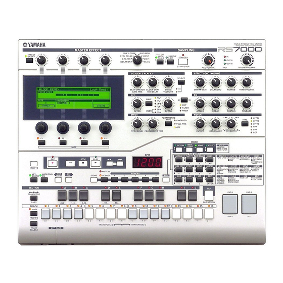
Page 8: Panel Layout
RS7000 PANEL LAYOUT Top Panel (Upper Section) MUSIC PRODUCTION STUDIO Integrated Sampling Sequencer MASTER EFFECT SAMPLING MULTI COMP RING MOD REAL TIME EFFECT CTRL DELAY V-DIST LOOP SAMPLE ON/OFF STANDBY REMIX EDIT D-FILTER LO-FI OUT A SLICE ISOLATION OUT B... - Page 9 RS7000 Top Panel (Lower Section) !5 @3 MODE PATT PATTERN SONG UTILITY UTILITY CHAIN SYSTEM MIDI SETUP MIDI FILTER SUB MODE GROOVE PLAY FX MIDI DELAY MIXER GROOVE PLAY FX MIDI DELAY MIXER GRID GROOVE HARMONIZE MIDI DELAY VOICE SELECT...
-
Page 10: Rear Panel
RS7000 Rear Panel THIS CLASS B DIGITAL APPARATUS COMPLIES WITH CANADIAN ICES-003. THIS DEVICE COMPLIES WITH PART 15 OF THE FCC RULES. OPERATION IS SUBJECT TO THE FOLLWWING TWO CONDITIONS: MUSICAL INSTRUMENT ( 1 ) THIS DEVICE MAY NOT CAUSE HARMFUL INTERFERENCE,AND MIDI CET APPAREIL NUMÉRIQUE DE LA CLASSE B EST CONFORME À... -
Page 11: Circuit Boards
RS7000 CIRCUIT BOARD LAYOUT <Rear View> MIDI <Bottom View> PS Cover Assembly Insulation Cover Power Supply Unit... - Page 12 RS7000 MIDI <Bottom View> Insulation Cover Power Supply Unit PNVR1 <Bottom View> LCD Assembly PNVR2 PNSW...
- Page 13 RS7000 WIRING (8P) (9P) MIDI PNVR1 POWER (7P) AC INLET PNVR2 ON/OFF CN22 Back Light Assembly (13P) (10P) (3P) Option CN 3 (7P) AIEB2 Power Supply Unit (8P) (4P) (9P) (8P) (40P) (3P) (4P) (40P) (26P) CN16 (11P) CN24 (9P)
- Page 14 Back Light Assembly PNSW PNVR2 PNSW SW LED 240 X 64 Dots CN12 (50P) Rotary Encoder PNSW-CN3 (11P), LCD Assembly CN4(9P) SCSI PNSW-CN2 (16P) PNVR2-CN2 (10P) PNVR2-CN4 (13P) CONNECTOR CN1 (8P) CN1 (26P) CN5 (11P), CN10 CN17 (2P) CN11 (26P) PNVR1 PNVR2 CN8 (16P),...
-
Page 15: Disassembly Procedure
RS7000 DISASSEMBLY PROCEDURE Bottom Assembly (Time required: About 5 minutes) 1-1 Remove the twelve (12) screws marked [720]. The bottom assembly can then be removed. (Fig.1) Bottom Assembly [720] [720] [720] [720] [720]: Bonding Tapping Screw-B 3.0X10 MFZN2BL (VQ049800) Fig.1... - Page 16 RS7000 <Rear View> [600] [450] [440B] Lithium Battery Battery VN103500 VN103600(Battery holder for VN103500) Notice for back-up battery removal Battery Push the battery as shown in figure, then the battery will pop up. [600] Druk de batterij naar beneden zoals...
- Page 17 RS7000 Shield Plate Assembly (Time required: About 25 minutes) You don’t need to remove the DM circuit board, the power supply unit and the MIDI circuit board to remove the shield plate assembly. 8-1 Remove the bottom assembly. (See procedure 1.) 8-2 Remove the SM circuit board assembly.
- Page 18 RS7000 9-5 PNSW Circuit Board: Pull out the four (4) encoder knobs marked [B] and remove the twelve (12) screws marked [150]. The Panel SW-Button assembly can then be removed. (Fig.6, 7) Pull out the thirty (30) buttons from the PNSW circuit board.
- Page 19 2. Switch off the RS7000 power, and unplug the power cord from the wall outlet. 3. Remove the screws holding the bottom cover in place. • Set the RS7000 upside down on the workbench and use a Phillips screwdriver to unscrew the 12 screws from the bottom (see illus-tration below).
- Page 20 RS7000 Replacind the Bottom Cover IMPORTANT When replacing the bottom cover, be sure that you do not get cables caught or pulled between the cover and main unit. This could cause broken connections or malfunctions. Procedure 1. Holding both sides of the bottom cover with both hands, lower the cover straight down from above to its original position.
- Page 21 • You need to use 72-pin SIMMs with access times of 70ns or less. The SIMM module size may be 4, 8, 16, or 32 MB. The RS7000 is designed for use with 32 bit SIMMs, but can also accept installation of 36 bit (parity-type) SIMMs.
- Page 22 NOTE When inserting SIMMs, always begin with the outer socket (i.e., the socket closest to the side of the RS7000 cover). SIMMs will not fit into the socket if you reverse this order. • Hold the SIMM with its cutout part facing the rear panel, and set the SIMM into the socket at an angle as shown in the figure below (1).
- Page 23 I/O (both optical and coaxial formats) and six assignable outputs to the RS7000. IMPORTANT Please note that the AIEB1 cannot be used in the RS7000. Procedure 1. Be sure that you have the following at hand before starting the installation.
- Page 24 • Connect the flat cable from the I/O expansion board (the thin, flat cable) to the corresponding connector on the RS7000’s circuit board (marked “C” in the illustration below: CN16). The connector is “keyed” so that it will only go in one way.
- Page 25 RS7000 7. Connect the 3-wire red/white cable. • Of the two red/white cables that extend from the I/O expansion board, first connect the 3-wire cable to the connector shown in the illustration below (CN7: 3-pin). Make sure that the direction is correct, and do not try to force the connection.
- Page 26 RS7000 • Use the bundle tie to secure the 3-wire cable, and the 4- wire cable (see illustration below). Bundle tie CAUTION Make sure that the cables are bundled below the circuit board. If any cables are pinched between the cover and I/O expansion circuit board when the bottom cover is replaced, broken connections or malfunctions may occur.
-
Page 27: Address
RS7000 LSI PIN DESCRIPTION HD6417709F80B (XV250B00) CPU DM: IC004 NAME FUNCTION NAME FUNCTION CKE/PTK5 CK enable / Port K Mode control /RAS3L/PTJ0 3L Row address strobe / Port J Vcc(RTC) Power supply +3.3V /RAS2L/PTJ1 2L Row address strobe / Port J... -
Page 28: Address
RS7000 XC9536-10VQ44C (XY110A00) CPLD DM: IC071 NAME FUNCTION NAME FUNCTION I/O/GCK3 Global Input/Output JTAG port Input/Output Ground Ground 3.3V/5V Power Supply +3.3V/+5V CCIO Input/Output Input/Output JTAG port I/O/GSR Global I/O/GTS2 Input/Output Power Supply +5V CCINT I/O/GTS1 Global Power Supply +5V... -
Page 29: Address
RS7000 PCM1800E/2K (XU770A00) ADC (Analog to Digital Converter) DM: IC084 NAME FUNCTION NAME FUNCTION VINL Analog input (L ch.) LRCK Sampling clock input/output VREF1 Reference 1 decoupling cap. Bit clock input/output REFCOM Reference decoupling common DOUT Audio data output VREF2 Reference 2 decoupling cap. - Page 30 RS7000 AK4393-VF-E2 (XW029A00) DAC (Digital to Analog Converter) DM: IC085 NAME FUNCTION NAME FUNCTION DVSS Digital ground BVSS Substrate ground DVDD Digital power supply VREFL Low level voltage reference MCLK Master clock VREFH High level voltage reference Power down mode...
- Page 31 RS7000 TC203C760HF-002 (XS725A00) SWP30B (AWM Tone Generator coped with MEG) Standard Wave Processor DM: IC059 NAME FUNCTION NAME FUNCTION (Ground) (Ground) HMD0 HMD1 HMD2 HMD3 HMD4 HMD5 Address bus internal register HMD6 HMD7 Wave memory data bus (Upper data memory)
- Page 32 RS7000 IC BLOCK DIAGRAM HD74HC14FPEL (XL094A00) HD74LV21AFPEL (IS002100) HD74LV32AFPEL (IS003200) TC74VHC14F-EL (XW876A00) Dual 4 Input AND HD74LVC32FP (XS792A00) 74VHC14SJX (XZ200A00) TC74HCT32AF(EL) (XY096A00) DM: IC033 Hex Inverter Quad 2 Input OR DM: IC003,010,015,021,053 DM: IC011,012,027,045,052,064 HD74LV74AFPEL (IS007400) TC74VHCT138AFEL (XZ137A00) HD74LV139AFPEL (IS013900)
- Page 33 RS7000 TC74VHCT574AFT (XY059A00) TC74HC4052AFT (XV869A00) TC74LVX4245FS (XU229A00) Octal D-Type Flip-Flop Differential 4-Channel Dual Supply Octal Bus Transceiver Multiplexer/Demultiplexer DM: IC020,026,035,036,042,044,081 DM: IC040,041,048 DM: IC006-009 VCCA VCCB VCCB Output Control Y-COM Y-COM X-COM X-COM Clock SC7SU04FEL (XI348A00) TC7W14F TE12L (XR336A00) TC7S66F...
-
Page 34: Parts List
RS7000 CIRCUIT BOARDS MIDI Circuit Board (XY235E0) ............34 SM Circuit Board (XV915C0) ............34 PNVR1 Circuit Board (XY237C0) .............35 PAD Circuit Board (XZ136C0) ............35 DM Circuit Board (XY235E0) ..........36,37/38,39 PNSW Circuit Board (XY236C0) ........40,41/42,43 PNVR2 Circuit Board (XY237C0) ..........44/45 MIDI Circuit Board... - Page 35 RS7000 PNVR1 Circuit Board MASTER EFFECT EFFECT ON/OFF to DM-CN1 Component side Pattern side PAD Circuit Board PAD1 PAD2 SPACE to DM-CN24 Pattern side Component side PNVR1: 2NA-V615490-1,2 PAD: 2NA-V615510...
- Page 36 RS7000 to Power Supply Unit-CN5 to Power Supply Unit-CN4 DM Circuit Board to PNVR2-CN4 not installed to PAD-CN1 to PN to PNSW-CN2 to PNSW-CN3 to PNVR2-CN2 to PNSW-CN4 to LCD to Back Light Assembly to SM-CN1 2NA-V615480-1...
- Page 37 RS7000 to Power Supply Unit-CN6 D-CN1 to PNVR1-CN1 to PNVR2-CN6 not installed to PNSW-CN1 to MIDI-CN22 SCSI FOOT SW CONTRAST INPUT OUTPUT L/MONO PHONES to AIEB2-CN2 to PNVR2-CN5 Component side (OPTION) to PNVR2-CN3 2NA-V615480-1...
- Page 38 RS7000 DM Circuit Board 2NA-V615480-2...
- Page 39 RS7000 Pattern side 2NA-V615480-2...
- Page 40 RS7000 PNSW Circuit Board to DM-CN4 SHIFT STOP PLAY MUTE/ SCENE OCT UP STORE KEYBOARD ARPEGGIO ON DOWN TRANSPOSE SECTION A SECTION B SECTION C SECTION D SECTION E 9~16 CAPS MUTE/ SOLO TRACK1/K! TRACK2/L# TRACK3/M$ TRACK6/P' TRACK7/Q( TRACK4/N% TRACK5/O&...
- Page 41 RS7000 to DM-CN8 MODE PATT PATTERN SONG UTILITY CHAIN GROOVE/7 PLAY FX/8 MIDI DELAY/9 MIXER/+/- VOICE EDIT/4 EFFECT/5 SETUP/6 MASTER/0 MODE MEMORY EXIT SAVE/1 LOAD/2 JOB/3 EDIT/ENTER TAP/PAD ASSIGN SECTION F SECTION G SECTION H SECTION I SECTION J TRACK9/S-...
- Page 42 RS7000 PNSW Circuit Board 2NA-V615500-2...
- Page 43 RS7000 Pattern side 2NA-V615500-2...
- Page 44 RS7000 PNVR2 Circuit Board to DM-CN2 to DM-CN21 to DM-CN9 to DM-CN20 to DM-CN6 Component side 2NA-V615490-1...
- Page 45 RS7000 Pattern side 2NA-V615490-2...
-
Page 46: Test Program
(D) Proceeding through the tests LCD, LED blink When you enter the test program, the following screen will appear first. Panel switches, rotary switches Encoders 1--4 //// RS7000 Test Program //// Knobs 1--22 Pads 1--2, foot switch 01:Battery :Press [ENTER] MIDI IN/OUT A... - Page 47 This test verifies that the panel switches and rotary switches 03:LED :Press [ENTER] are functioning correctly. (Test method) Turn all switches of the RS7000 on/off according to the LCD screen shown below. [-1] [+1] For the rotary switches, turn each one from the far left toward After the LCD screen shown below, the LEDs will light at intervals the far right, one position at a time.
- Page 48 [ < M E M O RY > 2 ] , [ < M E M O RY > 3 ] , [ < M E M O RY > 4 ] , //// RS7000 Test Program //// [<MEMORY>5], [EXIT], [PATTERN], [PATT CHAIN], [SONG],...
- Page 49 RS7000 //// RS7000 Test Program //// //// RS7000 Test Program //// yy: target value 06:Knob :->127->0->OK 07:Pad,FootSW : Pad1 :<yyy> xxx MASTER EFFECT xxx xxx xxx xxx xx: current value SEQUENCE PLAY FX xxx xxx xxx xxx xxx xxx xxx...
- Page 50 RS7000 (Test result display) //// RS7000 Test Program //// //// RS7000 Test Program //// //// RS7000 Test Program //// 09:MIDI B 09:MIDI B TIME OUT 08:MIDI A [-1] [+1] [-1] [+1] [-1] [+1] If the expected data was not received...
- Page 51 11. 1 kHz OUTPUT R sound 12. A/D -> D/A (MIC) This tests the signal route from the A/D input to D/A output. (By //// RS7000 Test Program //// default, the Gain is set to MIC.) 11:OUTPUT-R :Press [ENTER] //// RS7000 Test Program ////...
- Page 52 13. A/D -> D/A (LINE) a format/write/read/verify check on the Smart Media. It also check whether the Smart Media has been removed. //// RS7000 Test Program //// (Test method) 13:AD-DA(LINE) :Press [ENTER] First insert the Smart Media with protect turned on, and execute the test.
- Page 53 (Test result display) //// RS7000 Test Program //// If a result of NG is returned during this test, refer to section "(E) Proceeding to the next test if a result is NG" for the actions to...
- Page 54 RS7000 18. SIMM //// RS7000 Test Program //// //// RS7000 Test Program //// 19:SIMM(Full) :NG 18:SIMM :Press [ENTER] [-1] [+1] The display will indicate NG if any of the ICs are NG. [-1] [+1] When you enter this test, a SIMM read/write/verify test will be 20.
- Page 55 [-1] [+1] * Verify the SRAM backup power supply: This sets the settings with which the RS7000 was shipped from With the power turned off, verify that that the voltage between the factory. TP1 and GND on the DM sheet is greater than 2.6 V and less When you enter the test and it is completed normally, a sine than 3.2 V.
- Page 56 RS7000...
- Page 57 RS7000...
- Page 58 RS7000...
- Page 59 RS7000...
- Page 60 RS7000...
- Page 61 RS7000...
- Page 62 RS7000...
- Page 63 RS7000...
- Page 64 RS7000...
- Page 65 RS7000...
-
Page 66: Error Message
Wave Memory Optimize operation. Factory Set This message appears when the RS7000 is restored to the initial factory set- tings. The data in internal memory can be corrupted when the backup battery voltage runs too low, for example, and all data will automatically be restored... - Page 67 Card/Disk Not Ready A card or disk is not properly inserted in or connected to the RS7000. Unformatted Card/Disk The card or disk is not formatted, or the format is unusable by the RS7000. Check the card/disk contents. Write Protected The card or disk is write protected, or you have attempted to write to a read- only medium such as CD-ROM.
- Page 68 RS7000 Other Messages (Not Errors) Are you sure? NO[F2]/ Confirms that you want to execute a specified operation. Press [F2] or [F3] as YES[F3] required. Can’t Undo. Cancel [F2]/OK When some jobs are executed the internal memory becomes full and undo [F3] cannot be used.
- Page 69 RS7000...
- Page 70 RS7000...
- Page 71 RS7000...
- Page 72 RS7000 YAMAHA [ Music Priduction Studio --- sequencer part ] Date:22-MAR-2001 Model RS7000 MIDI Implementation Chart Version : 1.0 Transmitted Recognized Remarks Function... Basic Default 1-16 1-16 Channel Changed Default Mode Messages Altered ************** Note 0-127 0-127 Number : True voice **************...
- Page 73 RS7000 YAMAHA [ Music Production Studio --- voice part ] Date:04-APR-2001 Model RS7000 MIDI Implementation Chart Version : 1.0 Transmitted Recognized Remarks Function... Basic Default 1-16 1-16 Channel Changed Default M emorized Mode Messages 1-4 (m=1) *1 Altered ************** Note...
- Page 74 ==== UPDATE FROM CARD MODE==== Smart media floppy disk adaptor Completed. Reboot RS7000. Download the RS7000 updated program from the download page on the YSISS Homepage to the smart media. (YSISS URL >> http://plaza.yamaha.co.jp/ysiss/exindex.nsf) (Insert a smart media containing only the update program (0532os.pgm) into the card slot on the main unit.)
- Page 75 RS7000...
-
Page 76: Parts List
MUSIC SYNTHESIZER PARTS LIST CONTENTS OVERALL ASSEMBLY ..........2 PANEL SW-BUTTON ASSEMBLY ..5 PNVR1 CIRCUIT BOARD ......6 PNVR2 CIRCUIT BOARD ......6 ELECTRICAL PARTS ..........7 Notes : DESTINATION ABBREVIATIONS A : Australian model M : South African model B : British model O : Chinese model C : Canadian model... - Page 77 RS7000 OVERALL ASSEMBLY PNVR1 circuit board : See page 6. 810 790 470b 470a AS angle (V3883200) 670d 670c 670a 670b Panel SW-button assembly : PNVR2 circuit board : See page 6. See page 5. 490a 710a Bottom assembly...
- Page 78 RS7000 PART NO. DESCRIPTION REMARKS REF NO. RANK OVERALL ASSEMBLY RS7000 Overall Assembly (V640750) Overall Assembly (V641220) Overall Assembly (V641270) V6541600 Top Cover V7043600 LCD Assembly VT282300 EDMMR03Y00 VB390800 Connector Base Post PH 12P TE V7697900 Spacer Assembly VT210200 Back Light Assembly...
- Page 79 Graphic Mark (V229420) Label UL,C-UL (V328100) ACCESSORIES V3883200 AS Angle K-AA XZ795B00 CD-ROM 74min 12cm TOOLS for RS7000 CD-ROM V7025400 Smart Media X0288A00 CD-ROM ACID ACID for YAMAHA CD-ROM VT119800 AC Cord J 7A 125V 3P 2.5m VB927800 AC Cord...
- Page 80 RS7000 PANEL SW-BUTTON ASSEMBLY PART NO. DESCRIPTION REMARKS REF NO. RANK PANEL SW-BUTTON ASSEMBLY RS7000 (V703670) V6155000 Circuit Board PNSW V6976300 Function Button x4 WHITE PATTERN,PATT CHAIN,SONG, UTILITY V6576700 Function Button x4 BLACK GROOVE/7,PLAY FX/8, MIDI DELAY/9,MIXER/+/-, VOICE EDIT/4,EFFECT/5, SETUP/6,MASTER/0,SAVE/1,...
- Page 81 RS7000 PNVR1 CIRCUIT BOARD PART NO. DESCRIPTION REMARKS REF NO. RANK V7010100 CIRCUIT BOARD PNVR1 RS7000 Circuit Board PNVR 1/2 (V615490) V6747500 Function Button x1 BLACK EFFECT ON/OFF : New Parts RANK: Japan only PNVR2 CIRCUIT BOARD PART NO. DESCRIPTION REMARKS REF NO.
-
Page 82: Electrical Parts
RS7000 ELECTRICAL PARTS PART NO. DESCRIPTION REMARKS REF NO. RANK ELECTRICAL PARTS RS7000 V7009800 Circuit Board (XY235E0) V7010000 Circuit Board MIDI (XY235E0) V7010300 Circuit Board (XZ136C0) V6155000 Circuit Board PNSW (XY236C0) V7010100 Circuit Board PNVR1 (XY237C0) V7010200 Circuit Board PNVR2... - Page 83 RS7000 PART NO. DESCRIPTION REMARKS REF NO. RANK US064100 C0108 Ceramic Capacitor-B (chip) 0.0100 50V K US064100 C0109 Ceramic Capacitor-B (chip) 0.0100 50V K UF037100 C0110 Electrolytic Cap. (chip) 10 16V US064100 C0111 Ceramic Capacitor-B (chip) 0.0100 50V K US064100...
- Page 84 RS7000 PART NO. DESCRIPTION REMARKS REF NO. RANK US064100 -0221 Ceramic Capacitor-B (chip) 0.0100 50V K US145100 C0222 Ceramic Capacitor-F (chip) 0.1000 25V Z US064100 C0223 Ceramic Capacitor-B (chip) 0.0100 50V K US064100 -0228 Ceramic Capacitor-B (chip) 0.0100 50V K...
- Page 85 RS7000 PART NO. DESCRIPTION REMARKS REF NO. RANK UF037470 C0339 Electrolytic Cap. (chip) 47 16V UF037470 C0341 Electrolytic Cap. (chip) 47 16V US064100 C0343 Ceramic Capacitor-B (chip) 0.0100 50V K US064100 -0346 Ceramic Capacitor-B (chip) 0.0100 50V K VR329100 C0347 Mylar Capacitor (chip) 0.0010 50V J...
- Page 86 RS7000 PART NO. DESCRIPTION REMARKS REF NO. RANK XR336A00 IC013 TC7W14F TE12L INVERTER IS007400 IC014 HD74LV74AFPEL D-FF XL094A00 IC015 HD74HC14FPEL INVERTER IS007400 IC016 HD74LV74AFPEL D-FF IS007400 -019 HD74LV74AFPEL D-FF XY059A00 IC020 TC74VHCT574AFT D-FF XL094A00 IC021 HD74HC14FPEL INVERTER XR682A00 IC022 TC7S66F...
- Page 87 RS7000 PART NO. DESCRIPTION REMARKS REF NO. RANK XV763A00 IC087 OP275GSR OP AMP XT330A00 IC088 OPA2604AU OP AMP XV763A00 IC089 OP275GSR OP AMP XV763A00 IC090 OP275GSR OP AMP XP263A00 IC091 M5216FP-600C OP AMP IS013900 IC092 HD74LV139AFPEL DECODER XZ813100 IC093 MBM29F160BE-90TN...
- Page 88 RS7000 PART NO. DESCRIPTION REMARKS REF NO. RANK RD357100 -0075 Carbon Resistor (chip) 10K 63M J RD354470 R0076 Carbon Resistor (chip) 47 63M J RD354470 R0077 Carbon Resistor (chip) 47 63M J RD355330 R0078 Carbon Resistor (chip) 330 63M J...
- Page 89 RS7000 PART NO. DESCRIPTION REMARKS REF NO. RANK RD357100 R0184 Carbon Resistor (chip) 10K 63M J RD357100 -0187 Carbon Resistor (chip) 10K 63M J V4266800 R0188 Carbon Resistor (chip) 110 63M F V4266800 R0189 Carbon Resistor (chip) 110 63M F...
- Page 90 RS7000 PART NO. DESCRIPTION REMARKS REF NO. RANK VI198200 R0298 Metal Film Resistor (chip) 22.0K 1/10 D VI194100 R0299 Metal Film Resistor (chip) 470.0 1/10 D RD356470 R0300 Carbon Resistor (chip) 4.7K 63M J VI194100 R0301 Metal Film Resistor (chip) 470.0 1/10 D...
- Page 91 RS7000 PART NO. DESCRIPTION REMARKS REF NO. RANK RD357100 R0386 Carbon Resistor (chip) 10K 63M J RD356470 R0392 Carbon Resistor (chip) 4.7K 63M J RD355220 R0393 Carbon Resistor (chip) 220 63M J RD355220 -0396 Carbon Resistor (chip) 220 63M J...
- Page 92 RS7000 PART NO. DESCRIPTION REMARKS REF NO. RANK Cable Kit (V707850) VL472400 Piezoelectric Element 7BB-20-3A7 VL035600 Adhesive Tape US145100 C0001 Ceramic Capacitor-F (chip) 0.1000 25V Z US062100 C0002 Ceramic Capacitor-SL(chip) 100P 50V J US062100 C0003 Ceramic Capacitor-SL(chip) 100P 50V J...
- Page 93 RS7000 PART NO. DESCRIPTION REMARKS REF NO. RANK VT022800 LD020 LED Red SEL2210R TP8 SECTION D VT022800 LD021 LED Red SEL2210R TP8 SECTION E VT022800 LD022 LED Red SEL2210R TP8 SECTION F VT022800 LD023 LED Red SEL2210R TP8 SECTION G...
- Page 94 RS7000 PART NO. DESCRIPTION REMARKS REF NO. RANK V5914900 SW046 Push Switch SKPDADD010 H=9.5mm SECTION A/ALL V5914900 SW047 Push Switch SKPDADD010 H=9.5mm TRACK 3/M $ V5914900 SW048 Push Switch SKPDADD010 H=9.5mm SECTION B/1-8 V5914900 SW049 Push Switch SKPDADD010 H=9.5mm TRACK 4/N %...
- Page 95 RS7000 PART NO. DESCRIPTION REMARKS REF NO. RANK V5915000 * SW002 Rotary Switch SRBV18 MASTER EFFECT switch VV439800 SW003 Tact Switch SKQNAJ H=7mm REAL TIME LOOP REMIX VV439800 SW004 Tact Switch SKQNAJ H=7mm SAMPLE EDIT VZ085500 SW005 Tact Switch SKQNAM004A H=9.5mm...
-
Page 96: Parts List
RS7000 RS7000 OVERALL CIRCUIT DIAGRAM 1/2 (DM1/2, MIDI, PNSW, PNVR1, PNVR2, PAD, SM, LCD) SAMPLING PNVR2 to DM2/2 - CN20 to DM2/2 - CN21 REAL TIME MASTER EFFECT REC VOLUME MASTER VOLUME START/STOP MIDI MASTER EFFECT PNVR1 SEQUENCE PLAY FX... -
Page 97: Parts List
RS7000 RS7000 OVERALL CIRCUTO DIAGRAM 2/2 (DM2/2, LCD, AIEB2, Power Supply Unit) TRANSCEIVER MASK ROM 64M DM1/2 G-12 WAVE-L TRANSCEIVER DM1/2 H-12 SIMM TRANSCEIVER REGULATOR +3.3V to DM1/2 G-10 to DM1/2 F-9 DRAM 16M TRANSCEIVER MASK ROM TRANSCEIVER WAVE-H to DM1/2 D-10...