Table of Contents
Advertisement
Quick Links
Download this manual
See also:
User Manual
Advertisement
Table of Contents

Related Manuals for Lowrance Link-2


Summary of Contents for Lowrance Link-2
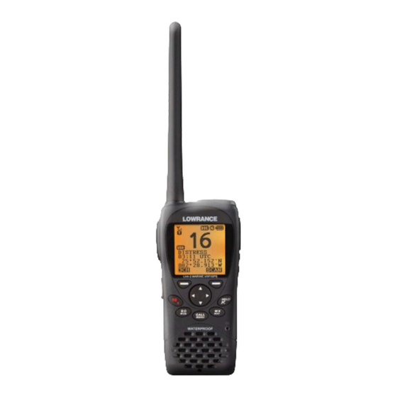
- Page 1 Link-2 Marine Handheld VHF Radio User Guide ENGLISH lowrance.com...
-
Page 2: Table Of Contents
Section 3 - Operating the radio ...............14 3-1 Power On/Off ........................... 14 Lowrance may find it necessary to change or end policies, regulations, and 3-2 Adjusting the Squelch level ....................... 14 special offers at any time. We reserve the right to do so without warning. - Page 3 7-1-1 Installing the battery pack ........................64 7-1-2 Initial charge ..............................64 Section 5 - Sending and Receiving DSC Calls ..........46 7-1-3 GPS connector ..............................65 5-1 What is DSC? ............................ 46 Lowrance - Link-2 Installation and Operation Instructions Lowrance - Link-2 Installation and Operation Instructions...
-
Page 4: Safety And Operational Information
This radio transmitter Link-2 (IC:4697A-LINK2) has been approved by Industry Canada Lowrance disclaims all liability for any use of this product in a way that may cause to operate with the antenna types listed below with the maximum permissible gain and required antenna impedance for each antenna type indicated. -
Page 5: Important
Section 1 - General information DSC functions will not operate until you have entered your user MMSI. Congratulations on your purchase of this handheld VHF marine radio Link-2, designed The radio channels installed into the radio may vary from country to country, depending and built using superior technology and craftsmanship. -
Page 6: Section 2 - Controls And Keys
If you try and add another favorite channel it will overwrite the existing CH3. CH1 and CH2 will remain unless you delete them. To delete a favorite channel, select that channel then hold Lowrance - Link-2 Installation and Operation Instructions Lowrance - Link-2 Installation and Operation Instructions... - Page 7 To enter a character, press CH to step through the alphabet or hold down to scroll through quickly. Lowrance - Link-2 Installation and Operation Instructions Lowrance - Link-2 Installation and Operation Instructions...
-
Page 8: Section 3 - Operating The Radio
• Pause for a few seconds after pressing PTT • Hold the microphone 5 to 10 cm (2 to 4 inches) away from your mouth and speak at a normal volume. Lowrance - Link-2 Installation and Operation Instructions Lowrance - Link-2 Installation and Operation Instructions... -
Page 9: Dual Watch Operation
• GO – Reset the cross track error (XTE) 1.5 seconds). • SQL – Go to WP select Mode • SQL – Go to Plotter Mode • Other key – error beep. Lowrance - Link-2 Installation and Operation Instructions Lowrance - Link-2 Installation and Operation Instructions... -
Page 10: Wp Select Mode
Go to normal mode • Other key Error beep. To avoid screen clutter, a maximum of 5 waypoint icons closest to you plus the active waypoint are shown. Lowrance - Link-2 Installation and Operation Instructions Lowrance - Link-2 Installation and Operation Instructions... -
Page 11: Section 4 - Advanced Setup
_° _ . _ _ _N FISH1 12°32.233’N • ERASE TRACK _ _° _ . _ _ _ _° _ . _ _ _W 132°45.651’W • RESET Lowrance - Link-2 Installation and Operation Instructions Lowrance - Link-2 Installation and Operation Instructions... -
Page 12: Edit A Waypoint
ENTER. Select WP EDIT and press ENTER. The waypoint details are displayed and the cursor is positioned at the first character of the name. Lowrance - Link-2 Installation and Operation Instructions Lowrance - Link-2 Installation and Operation Instructions... -
Page 13: Set A Route To A Stored Waypoint
MENU SELECT. to save the new entry. (If it is not correct, select EXIT). MENU SELECT LAMP TIMEOUT ►ALWAYS ON WAYPOINT ►BACKLIGHT 5 SECOND LAMP 15 SECOND Lowrance - Link-2 Installation and Operation Instructions Lowrance - Link-2 Installation and Operation Instructions... -
Page 14: Edit A Buddy Name
This will repeat every 4 hours if you do not enter the position data manually. After you have entered the position data, you must update it within 23.5 hours otherwise NO GPS alert sequence repeats. Hold down CALL/MENU for about 3 seconds. Lowrance - Link-2 Installation and Operation Instructions Lowrance - Link-2 Installation and Operation Instructions... -
Page 15: Manual (Manually Enter Your Position And Utc Time)
The cursor is at ON (to show your position). If you want to hide your position, move the cursor to OFF. Press ENTER to confirm your selection. Lowrance - Link-2 Installation and Operation Instructions Lowrance - Link-2 Installation and Operation Instructions... -
Page 16: Settings: Time Format (12 Or 24 Hour Clock)
Select ON/OFF as desired, in this example, ON has been selected, so if the GPS signal Press ENTER to confirm the selection. is lost, then the NO GPS alert will sound. Lowrance - Link-2 Installation and Operation Instructions Lowrance - Link-2 Installation and Operation Instructions... -
Page 17: Gps Alert
To delete the channel name, just select DELETE then press ENTER. Press ENTER to confirm the new channel name and then press cancel to return to the menu. Lowrance - Link-2 Installation and Operation Instructions Lowrance - Link-2 Installation and Operation Instructions... -
Page 18: Radio Setup
UNITS ►METRIC RING VOLUME KEY BEEP NAUTICAL 4-7-8 Set NMEA output (NMEA OUT) ►UNITS STATUTE RADIO SETUP NMEA OUT ►ON WATCH MODE WX ALERT ►NMEA OUT Lowrance - Link-2 Installation and Operation Instructions Lowrance - Link-2 Installation and Operation Instructions... -
Page 19: Favourite Channel Setup (Fav Ch Setup)
4-8 DSC setup The Link-2 can output NMEA0183 sentences when docked in the charging cradle. Supported sentences are: RMC, GGA, GLL, GNS, GSV. The DSC Setup submenu is used to set behavior of the DSC functions. Select RADIO SETUP then NMEA OUT. -
Page 20: Dsc Setup
The cursor is at STORE, check that it is correct and, if so push ENTER to save the new entry. (If it is not correct, select CANCEL). Lowrance - Link-2 Installation and Operation Instructions Lowrance - Link-2 Installation and Operation Instructions... -
Page 21: Response To Individual Calls (Indiv Reply)
• AUTO automatically replies to any incoming LL polling requests from any of your Select ON to enable automatic channel switching. buddies Select OFF to disable automatic channel switching. • OFF ignores all incoming buddy LL polling requests. Lowrance - Link-2 Installation and Operation Instructions Lowrance - Link-2 Installation and Operation Instructions... -
Page 22: Dsc Test Reply (Test Reply)
10 minutes of non-activity. and return to the menu. You can view your stored ATIS MMSI at anytime by selecting ATIS MMSI in the ATIS SETUP menu. Lowrance - Link-2 Installation and Operation Instructions Lowrance - Link-2 Installation and Operation Instructions... -
Page 23: Enable Atis Functionality (Atis Select)
Select yes, press ENTER to reset the radio and return to the menu. Select ON or OFF as required, then press ENTER to confirm the selection. Lowrance - Link-2 Installation and Operation Instructions Lowrance - Link-2 Installation and Operation Instructions... -
Page 24: Dsc Call Types
Makes an Urgency, Safety or Routine call to all ships. A confirmation screen follows the priority selection of these options. The Safety call is for advisory Due to EU regulations, DSC may not be available in the Link-2 (EU) model. alert only. -
Page 25: Send An Individual Call (Individual)
The cursor is at LAST CALL. Move the cursor to GROUP and push ENTER. The names of your groups are displayed. Select the group that you want to call and press ENTER. Lowrance - Link-2 Installation and Operation Instructions Lowrance - Link-2 Installation and Operation Instructions... -
Page 26: Send An All Ships Call (All Ships)
10. Select YES, then press ENTER to retry the call. This cycle repeats twice. If the call still cannot be placed, the radio returns to normal operation. Lowrance - Link-2 Installation and Operation Instructions Lowrance - Link-2 Installation and Operation Instructions... -
Page 27: Reply To A Call In Your Distress Log (Distress Log)
Select TRACKLIST. Any buddies that are already on the track list will be listed. Note: To delete a buddy from the track list, select the buddy that you want to delete, then Lowrance - Link-2 Installation and Operation Instructions Lowrance - Link-2 Installation and Operation Instructions... -
Page 28: Select Your Track Buddy
►TRACK BUDDY TRACK LIST BUDDY #3 OFF Note: The Link-2 is capable of receiving and displaying the LL position data at normal or enhanced resolution. Press CALL/MENU to enter DSC MODE, then select TRACK BUDDY. 5-11 Make a DSC test call (DSC TEST) Select SET BUDDY and scroll down to your desired buddy. -
Page 29: Acknowledging An Incoming Dsc Test Call
Press PTT to initiate voice contact on current display channel. TRACK BUDDY 999°99.000’Y DSC TEST The call data is stored in your Call Log (see Section 7-8). ►MMSI/GPS Lowrance - Link-2 Installation and Operation Instructions Lowrance - Link-2 Installation and Operation Instructions... -
Page 30: Receiving An Individual Call (Indiv)
Section 5-2). connected chart-plotter / MFD. Press ACCEPT soft key to switch to the designated channel immediately, or press EXIT to return the current DSC receive process. Lowrance - Link-2 Installation and Operation Instructions Lowrance - Link-2 Installation and Operation Instructions... -
Page 31: Section 6 - Distress Calls
Note: The call data is stored in the Distress Log and location data (DSC & DSE) sentence will • Press ▲ to display the transmitted Distress call information. ▼ be output on the NMEA0183 port for indication on a connected chart-plotter / MFD. Lowrance - Link-2 Installation and Operation Instructions Lowrance - Link-2 Installation and Operation Instructions... -
Page 32: Rel)
Note: The call data is stored in the Distress Log and location data (DSC & DSE) sentence is sent on the NMEA0183 port for indication on a connected chart-plotter / MFD. DISTRESS ACK FROM 567890123 FIRE ▼ 00:01 Lowrance - Link-2 Installation and Operation Instructions Lowrance - Link-2 Installation and Operation Instructions... -
Page 33: Section 7 - Installation Instructions
7-1-2 Initial charge You can either charge the Li-Polymer battery pack when it is attached to the radio or separated: Connect to NMEA0183 port on MFD NMEA connector Lowrance - Link-2 Installation and Operation Instructions Lowrance - Link-2 Installation and Operation Instructions... -
Page 34: Mounting Battery Charger To Flat Surface
The belt clip supplied with your radio allows you to attach the radio to your belt. To install the belt clip: slide the belt clip to the back of your radio, make sure that the fitting Groove is aligned. Lowrance - Link-2 Installation and Operation Instructions Lowrance - Link-2 Installation and Operation Instructions... -
Page 35: Installing And Removing The Antenna
Never leave your radio in a closed car or trunk; the extremely high temperatures Hum and Noise Attenuation 40 dB generated in hot weather can damage the electronics. Audio Distortion Lowrance - Link-2 Installation and Operation Instructions Lowrance - Link-2 Installation and Operation Instructions... -
Page 36: Gps And Navigation
157.300 161.900 Public Correspondence TELEPHONE 157.350 161.950 Public Correspondence TELEPHONE 157.400 162.000 Public Correspondence TELEPHONE 156.025 160.625 Public Correspondence TELEPHONE 156.075 160.675 Port Operations PORT OPS Lowrance - Link-2 Installation and Operation Instructions Lowrance - Link-2 Installation and Operation Instructions... -
Page 37: Special Notes On International Channel Usage
KEY: S = Simplex operating channel; D = Duplex operating channel. 156.325 156.325 Port Operations PORT OPS 156.375 156.375 Commercial, bridge-to-bridge, 1W with BRIDGE COM Power-up Lowrance - Link-2 Installation and Operation Instructions Lowrance - Link-2 Installation and Operation Instructions... -
Page 38: Special Notes On Usa Channel Usage
This channel is only available on DSC enabled radios. 156.025 160.625 Public Correspondence TELEPHONE 156.075 156.075 U.S. Government, Canadian Coast Guard Yes UNAUTHORIZED KEY: S = Simplex operating channel; D = Duplex operating channel. Lowrance - Link-2 Installation and Operation Instructions Lowrance - Link-2 Installation and Operation Instructions... -
Page 39: Special Notes On Canada Channel Usage
Lightly shaded simplex channels 21A, 23A, 61A, 64A, 81A, 82A, and 83A cannot be lawfully used in Canada waters unless special authorization is obtained from the Canadian Coast Guard. Not for use by the general public. Lowrance - Link-2 Installation and Operation Instructions Lowrance - Link-2 Installation and Operation Instructions... -
Page 40: Appendix C - Eu Inland Waterway Channels
156.775 156.775 channels as soon as possible available for the radiotelephone service on Inland 156.8 156.8 Waterways and/or the required service catego ry. Lowrance - Link-2 Installation and Operation Instructions Lowrance - Link-2 Installation and Operation Instructions... -
Page 41: Special Channels
NL - Netherlands UK - United Kingdom In the Czech Republic this channel is used for service category ship-to-port GR - Greece NO - Norway authorities. Lowrance - Link-2 Installation and Operation Instructions Lowrance - Link-2 Installation and Operation Instructions... - Page 42 1177...
Need help?
Do you have a question about the Link-2 and is the answer not in the manual?
Questions and answers