Table of Contents
Advertisement
maintaining the set temperature of the boiler by controlling the blower and the
feeder
ability to operate a boiler with an emergency grate
infinitely adjustable blower operation and adjustable power
programmable boiler blow
adjustable damping time and automatic disabling of control when boiler no fuel
is available
controlling the central heating circulating pump operation
ability to switch hot water priority on and off
control of the domestic hot water heater charging pump depending on the
required temperature
ability to operate the boiler and the DHW pump under one of several weekly
programs installed in the Master 500 controller
COMFORT SYSTEM function, which protects the pump against limescale
protection system – TERMIK thermal fuse
function protecting the system against freezing and overheating of the boiler
temperature sensor failure alarm
adjustable display brightness – increased during adjustment of settings
ability to connect remote control with a sound alarm system
ability to connect a room thermostat
1
Operating instructions
for screw feeder or piston feeder
The Master 500 controller is designed to
control the boiler operation with
automatic feeding of fuel, CH pump and
DHW pump in central heating systems.
Advertisement
Table of Contents

Related Manuals for DK System Master 500


Summary of Contents for DK System Master 500
- Page 1 Operating instructions for screw feeder or piston feeder The Master 500 controller is designed to control the boiler operation with automatic feeding of fuel, CH pump and DHW pump in central heating systems. maintaining the set temperature of the boiler by controlling the blower and the...
-
Page 2: Description Of The Controller Components
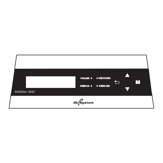
Description of the controller components 3 4 5 Display Signal LEDs: FEEDER CH PUMP DHW PUMP The back button Adjust setting UP button (+) MENU button Adjust setting DOWN button (-) Fig.1 Description of the controller components Operating screen description Current temperature Current time of the boiler... -
Page 3: Installation Recommendations
Installation Recommendations The controller is designed for use with boilers with automatic feeding of fuel. The controller must be installed by an authorized person. The controller must be connected to a socket with a protective contact. It is required that the boiler had its own safeguards against excessive temperature rise of the boiler caused e.g. -
Page 4: Controller Installation
Electrical connection and sensors diagram Power supply DHW Pump CH Pump Feeder ~230 V Fig.3 Wiring diagram to connect power cables Fig.4 Wiring diagram to connect sensors Controller installation 1. The controller is designed to be mounted on the boiler. 2. -
Page 5: Connection Of The Controller To The Electrical System
Connection of the controller to the electrical system 1. Connect the fan, pump and feeder with the appropriate power cables (see - Figure 3). 2. Install all necessary sensors (and reed relay for the piston feeder) acc. to Fig.4 and Fig.6. 3. - Page 6 10. DHW heater sensor 11. Remote control 12. Room thermostat Fig.6 Master 500 wiring diagram First start When you first run the controller, the display flashes the clock and day of the week. To set the correct time and date, press , and then use the "+", “-"...
- Page 7 After finishing the settings and double-pressing of , you will be taken to the main screen. Starting the boiler and setting the operating parameters 1. Open the ash pit door. 2. Start the feeder manually (see Manual operation - Testing outputs) and wait until coal shows at the level of the blow holes.
- Page 8 DHW heater operating parameters setting During operation of the controller press the button ; the HOT WATER display will be shown. Setting the temperature of the domestic hot water heater. Pressing again will take you to the desired temperature setting for the boiler. Set the required temperature, using the buttons: to increase the setting or to reduce...
- Page 9 Hysteresis of the DHW pump A parameter that specifies the number of degrees Celsius by which the temperature must fall on the domestic hot water heater below the set point for the domestic hot water pump to turn on. Change range: from 2 °C to 9 °C. Selecting or changing the CH and DHW operating mode You can choose the mode in which the controller operates.
- Page 10 Note: SUMMER mode, indicated by the symbol on the screen means that outside of the heating season the heating pump will not operate and all the heat generated by the boiler is designed to heat domestic hot water. ON / OFF. Operation of room thermostat You can connect a room thermostat (see Fig.
-
Page 11: Shutting Down The Boiler
Central heating pump - operation time A parameter that specifies the CH pump operation time (calculated in seconds) when interoperability with the room thermostat. Change range: from 0 s to 240 s. Pressing again takes you to the next setting. Central heating pump - break time This parameter specifies the time interval in the operation of the CH PUMP (calculated in minutes) when interoperability with the room thermostat. -
Page 12: Stop Mode
To switch on the DAMPING mode, press and hold for a few seconds the - the screen will show DAMP. When the temperature in the boiler drops below "dt damp", countdown to damping will start (see - Adjustment of damping time), and then the boiler will shut down - which will be indicated by the STOP message. -
Page 13: Operating Parameters - Heating - Feeder Operation
Operating parameters - HYSTERESIS The parameter defines the number of degrees Celsius by which the temperature must fall below the setpoint, at which the controller will resume the HEATING mode – at this point the feeder will start regular operation as set by the parameters Operating parameters - HEATING - feeder operation and Operating parameters - HEATING - feeder pause) ,fan will be switch on and will keep running until the boiler reaches the required temperature. -
Page 14: Operating Parameters - Heating - Blowing Power
In the case of the piston feeder the scope and factory setting is changed. Change range: from 10 s to 900 s. Operating parameters - HEATING - blowing power This parameter allows you to set the maximum power at which the fan will operate during HEATING mode. - Page 15 Operating parameters - MAINTAINING - feeder operation This parameter specifies the time (in seconds) of the duration fuel feeding (feeder operation) in the MAINTAINING mode. Change range: from 1s to 250 s. If the piston feeder is used, its time of operation in maintaining mode will be defined by the number of cycles and not by seconds.
- Page 16 Operating parameters - MAINTAINING - fan operation This parameter defines the time of operation of the fan (in seconds) in the MAINTAINING mode. Change range: from 0 s to 90 s. Pressing again takes you to the next setting. Note: In the MAINTAINING mode the fan starts at the same time as the feeder.
-
Page 17: Operating Parameters - Ch Pump Oper. Threshold Control
Fan - smooth operation The parameter enabling or disabling smooth operation of the fan. The principle of smooth operation is that the fan progressively reduces its speed when the temperature of the boiler approaches the desired setpoint. Change range: yes / no. Pressing again takes you to the next setting. -
Page 18: Emergency Grate - Blowing Power
Use the buttons to select the desired setting. Change range: no / yes Pressing again takes you to the next setting. Emergency grate - blowing power This parameter allows you to set the maximum power at which the fan will operate when the emergency grate is used. -
Page 19: Manual Operation - Blowing Power
Manual operation This function is used testing the correctness of the connected equipment. To enter the manual operation menu, press the button ; the display will show HOT WATER. Then use the buttons to select the MANUAL OPERATION option and confirm with Manual operation - blowing power This parameter allows you to set the power at which the fan is to operate in manual... - Page 20 In order to enter the temperatures window, press the button the display will show HOT WATER. Then use the button to select the TEMPERATURES option and confirm No temperature rise This parameter defines the time (calculated in seconds), during which it is expected that the temperature will rise during operation in the HEATING mode.
-
Page 21: Weekly Program - Reduction Of Boiler Temperature
Weekly program The WEEKLY PROGRAM functionality enables boiler and DHW pump operation according to one of several programs. To enter the weekly program menu, press the button the display will show HOT WATER. Then use the button to select the WEEKLY PROGRAM and confirm with Weekly program - enabling This parameter determines whether the weekly program applies to central heating or hot water. - Page 22 Pressing again takes you to the next setting. Weekly program - program selection This parameter allows you to select one of the available weekly programs. Change range: family / work / senior / custom. The parameters of available programs Work program Family program 07:00 - 22:00 08:00 - 22:00...
- Page 23 Make the changes with the keys, and approve each setting with Setting the ON/OFF parameters to "--:--” means that in a specific period the pump ON and OFF time was not set. Language Nthis setting is used to set the language for displaying of messages. To enter the language setting menu, press and hold the button , the display will show HOT WATER Then use the...
-
Page 24: Factory Settings
Factory settings This function is used to remove the parameters set by the user and return to the factory settings. To access the factory settings menu, press the ; the display will show HOT WATER. Then use the to select the FACT. SETGS. option and confirm with Confirmation of parameters change to factory settings is done with the button. - Page 25 Emergency stop of the piston feeder The parameter defines the time (in seconds) ensuring a full cycle of the feeder drawer. If, for some reasons, it is jammed, then, after that time the feeder and the fan will be stopped in emergency mode, and the screen will indicate a feeder fault - see more Alarms - piston feeder drawer fault.
- Page 26 Starting the DAMPING process A parameter that specifies at how many degrees Celsius below the temperature set on the boiler for the damping countdown to start, and then to shut the boiler down, see Adjustment of damping time. Change range : from 10 °C to 30 °C.
- Page 27 Ejection of fuel into the furnace in a critical situation Parameter specifying the time (counted in minutes), during which the feeder will press the fuel into the furnacein a situation when the temperature in the feeder reaches a critical level - for more information see Alarm – feeder temperature. Change range: from 1 min to 50 min.
-
Page 28: Maintenance Menu - Alarm
Maintenance menu - Alarm The menu has settings for triggering the alarm for excessive temperature on the boiler.The menu has settings for triggering the alarm for excessive temperature on the boiler. To access the alarm menu, press and hold for a few seconds the button, the screen displays MAINT PARAM Then press to select ALARM and confirm... -
Page 29: Alarm - Sound
Alarm - feeder temperature This parameter allows you to set the temperature above which an alarm is triggered. Change range: from 30 °C to 99 °C. Pressing again takes you to the next setting. Alarm - no temperature rise Parameter allowing enabling or disabling the boiler temperature rise monitoring functionality No temperature rise. -
Page 30: The Comfort System Function
The controller will prompt you to enter the access code. Use the buttons to set the access code and confirm with Note: The access code is known only to the maintenance technician. A screen will be displayed for setting the number of months until the next maintenance check Make the change using the buttons;... -
Page 31: Remote Control (Optional)
Remote control - optional The controller is designed for remote control (see Fig. 4), which enables control of the current temperature of the boiler, changing the set temperature of the boiler and a number of other features which improve user comfort. Built-in beeper emits a sound when the temperature rises to a dangerous level specified by the user. -
Page 32: Damaged Dhw Temperature Sensor
Feeder sensor damaged When the feeder temperature sensor is damaged, the display shows Feed Sens (fan operation will stop and the feeder will continue for the time set in item Ejection of fuel into the furnace in a critical situation), instead of the temperature -- will be displayed and a continuous sound will be generated (as long as this option is enabled - see Alarm - sound). -
Page 33: Piston Feeder Drawer Fault
Piston feeder drawer fault When there is a fault / jamming of the piston feeder mechanism (the drawer will not move), then the screen will show Feeder (the feeder and fan will be stopped) and a continuous sound will be generated (as long as this option is enabled - see Alarm - sound). -
Page 34: Specifications
Specifications Measured temperature range from - 9 °C to + 120 °C Boiler temperature setting range from + 45 °C to + 80 °C Hot water heater temperature range from + 40 °C to + 70 °C Temperature setting range for the CH pump from + 30 °C to + 70 °C Smooth start of the fan Adjustable maximum fan power... - Page 36 INFORMATION ON WASTE ELECTRICAL AND ELECTRONIC EQUIPMENT Disposal of Waste Electrical and Electronic Equipment (Applicable in the European Union and other European countries with separate collection systems). This symbol on the product or its packaging (pursuant to the Act of July 29, 2005 on Waste Electrical and Electronic Equipment) states that this product may not be treated as household waste.
Need help?
Do you have a question about the Master 500 and is the answer not in the manual?
Questions and answers