
Related Manuals for McIntosh MC611


Summary of Contents for McIntosh MC611
-
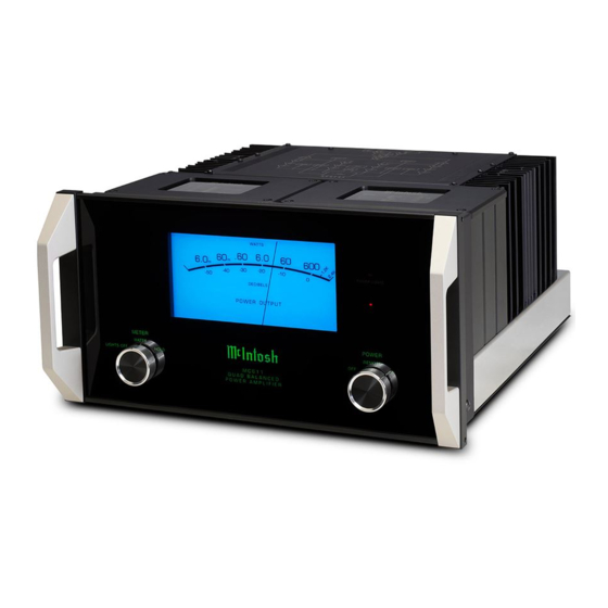
Page 1: Power Amplifier
McIntosh Laboratory, Inc. 2 Chambers Street Binghamton, New York 13903-2699 Phone: 607-723-3512 www.mcintoshlabs.com MC611 Quad Balanced Power Amplifier Owner’s Manual... -
Page 2: Table Of Contents
Technical Assistance and Customer Service ....2 Purchase Date: _______________________________ it to the McIntosh MC611. Table of Contents ............2 In the event the MC611 over heats, due to improper General Information ........... 2 Dealer Name: ________________________________ ventilation and/or high ambient temperature, the Connector and Cable Information ......3... -
Page 3: Connector And Cable Information
• Power Output trouble free operating life. Built-in Thermal Protection XLR Connectors The MC611 is a Power Amplifier with a capability of Circuits guard against overheating. Below is the Pin configuration for the XLR Balanced 600 watts into 2, 4 or 8 ohm speakers with less than Input, Input/Output Connectors on the MC611. -
Page 4: Dimensions
Dimensions Dimensions The following dimensions can assist in determining the best location for your MC611. Front View of the MC611 " 44.45cm " Side View of the MC611 " 7/16 22.54cm 23.97cm " 3/16 51.27cm " 15/16 45.55cm Rear View of the MC611 "... -
Page 5: Installation
Installation Installation 17" The MC611 can be placed upright on a table or 43.18cm shelf, standing on its four feet. It also can be custom installed in a piece of furniture or cabinet of your Opening for Ventilation choice. The four feet may be removed from the bottom of the MC611 when it is custom installed as outlined below. -
Page 6: Rear Panel Connections And Switch
AC outlet. Refer a 4 ohm Loudspeaker to the rear panel to determine the correct voltage Caution: The Loudspeaker Negative Connections are above chassis ground. Do not combine any connections together, ground them or connect with another MC611. -
Page 7: How To Connect
3. Using a suitable tool remove the two screws from put Terminal and rotate it one is stranded, carefully twist the strands together the MC611 Rear Panel and temporarily place them quarter of a turn (90° ) to secure as tightly as possible. -
Page 8: Output Terminals And How To Connect
MC611 Rear Panel with the previously removed Screws. Refer to figure 5. Cover Screws Cover Screws 10. Connect the MC611 power cord to an active AC Figure 5 (Inside USA and Canada) Figure 6 (Outside USA and Canada) outlet. 6. Attach the previously prepared bare wire cable ends... - Page 9 5. Using a suitable tool remove the two screws from How to Connect for Bi-Amp fully twist the the MC611 Rear Panel and temporarily place them strands together Caution: Do not connect the AC Power Cord to the in a safe place. Refer to figure 1.
-
Page 10: For Bi-Amp
11. Attach the Terminal Connections Cover to the MC611 Rear Panel with the previously removed Screws. Refer to figure 5. Cover Screws 12. Connect the MC611 power cord to an active AC Figure 5 (Inside USA and Canada) outlet. 8. Attach the previously prepared bare wire cable... -
Page 12: Front Panel Displays And Controls
Front Panel Displays and Controls LED indicates when the Amplifier POWER GUARD circuit activates Meter indicates the Output Standby Power of the amplifier On Indicator METER Switch selects POWER Switch Turns AC Power Off, the display modes of the Remote, AC Power On Power Output Meter and Meter Illumination... -
Page 13: How To Operate
Note: If the Power Save Circuitry has switched Power level until a higher power peak passes Refer to figures 9 and 10. to the MC611 OFF, place the POWER in the OFF through the amplifier. The meter point- Lights Off - Meter... -
Page 14: Technical Description
The distortion limits for the owner would never accept the approximately 100 mise, using the most advanced McIntosh circuit design MC611 are no more than 0.005% at rated power output times higher distortion of many non-feedback designs. concepts. - Page 15 This optimum load the high fidelity industry. may vary consider- The high efficiency circuit ably from what a design of the MC611 contrib- loudspeaker re- utes to low operating tem- quires. In the case peratures. More than 1400 of more than one...
- Page 16 The different types of protection circuits waveforms. When the With Power Guard incorporated in the MC611 insure a long and safe know how difference exceeds 0.3%, to do it operating life. This is the Power Guard acti-...
- Page 17 Also, most owners desire one power switch for the Figure 23 whole audio system. The MC611 is equipped with a circuit that provides remote Power Control from a Mc- Intosh A/V Control Center. Refer to figure 26. When the A/V Control Center is switched On, a (+5V) signal operates the power relay in the MC611.
-
Page 18: Specifications
240V ~ 50/60Hz at 3.3 Amps 20Hz to 20,000Hz 22,000 ohms Unbalanced Standby: less than 0.5 watt Note: Refer to the rear panel of the MC611 for the cor- rect voltage. Total Harmonic Distortion Voltage Gain 0.005% maximum harmonic distortion at any power... -
Page 19: Packing Instruction
If a shipping carton or any of the interior part(s) are needed, please call or write Customer Service Depart- ment of McIntosh Laboratory. Refer to page 2. Please see the Part List for the correct part numbers. Quantity... - Page 20 McIntosh Laboratory, Inc. 2 Chambers Street Binghamton, NY 13903 www.mcintoshlabs.com The continuous improvement of its products is the policy of McIntosh Laboratory Incorporated who reserve the right to improve design without notice. Printed in the U.S.A. McIntosh Part No. 04184201...
Need help?
Do you have a question about the MC611 and is the answer not in the manual?
Questions and answers