
Related Manuals for MachineryHouse CL-60A


Summary of Contents for MachineryHouse CL-60A
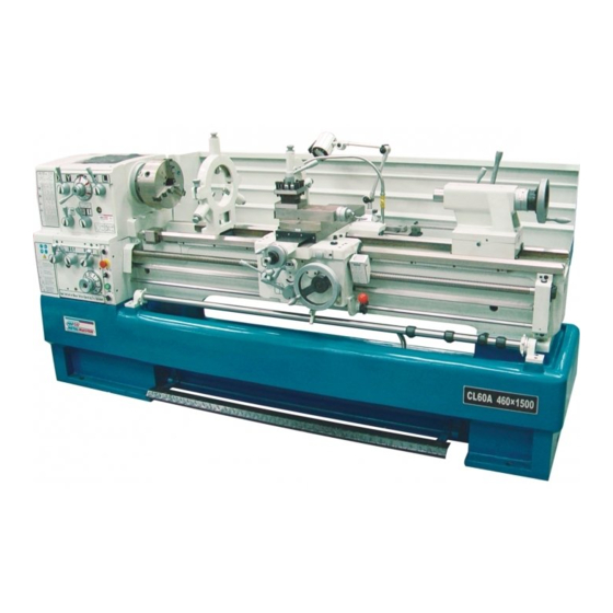
- Page 1 Page 1 Instructions Manual for CL-60A (L604) 07/09/2017 INSTRUCTION MANUAL CL-60A Centre Lathe (415V) 460 x 1500mm Turning Capacity L604...
- Page 2 Page 2 Instructions Manual for CL-60A (L604) 07/09/2017 7/7/08 L604 /L604D CL-60A ( C6246 ) # JK---- SPARES Spare parts manual...
-
Page 3: Table Of Contents
Page 3 Instructions Manual for CL-60A (L604) 07/09/2017 Operation Manual Contents ………………………………………………………………….4 Specification 1. High Speed Precision Lathe 1-1 Constructional Indication…………………………………………………….8 2. Unpacking and Installation 2-1 Points for Unpacking……………………………………………………….10 2-2 Unloading of the Machine…………………………………………………..10 2-3 Construction of the Ground…………………………………………………11 2-4 Cleaning…………………………………………………………………….11 2-5 Level Adjustment…………………………………………………………...11... -
Page 4: Table Of Contents
Page 4 Instructions Manual for CL-60A (L604) 07/09/2017 5-1 Lead Screw Drive...................24 5-2 Cutting Thread……………………………………………………………...24 5-3 Thread Dial Indicator..................24 5-4 Thread and Feed Table...................26 6. Lubrication 6-1 Lubrication in Headstock…………………………………………………...30 6-2 Lubricating in Gear Box and Apron………………………………………...30 6-3 Useful Reference Lubricating Table for Other Mechanism………………...30 6-4 Lubrication Location………………………………………………………..31... - Page 5 Page 5 Instructions Manual for CL-60A (L604) 07/09/2017 Specification C6246H×1000 / C6246H×1500 / C6246H×2000 Models Capacity Swing Over Bed φ460mm Swing Over Cross Slide φ270mm Swing in Gap Diameter×Width 690×165mm Height of Center 230mm Distance Between Centers 1000mm 1500mm 2000mm...
- Page 6 Page 6 Instructions Manual for CL-60A (L604) 07/09/2017 Weight & Measures Machine Space Required (L×W×H): cm 220×108×137 / 275×108×137 / 325×108×137 Packing Case Dimensions (L×W×H): cm 225×112×162 / 280×112×156 / 330×113×156 Net Weight 1720kg 1970kg 2120kg Gross Weight 2045kg 2330kg...
-
Page 7: High Speed Precision Lathe 1-1 Constructional Indication
Page 7 Instructions Manual for CL-60A (L604) 07/09/2017 1. High Speed Precision Lathe 1-1 Constructional Indication... - Page 8 Page 8 Instructions Manual for CL-60A (L604) 07/09/2017 Description Description Main Spindle Speed Change Lever Saddle Fixture Screws High/Low Speed Change Lever Foundation Adjustment Bolts Main Spindle Speed Change Lever Start Lever Forward/Reverse Lever 4-Position Auto Stop Lever Thread Feed Select Lever...
-
Page 9: Unpacking And Installation 2-1 Points For Unpacking
Page 9 Instructions Manual for CL-60A (L604) 07/09/2017 2. Unpacking and Installation 2-1 Points for Unpacking For short distance transportation of this machine, fix it onto the truck by hemp rope: while for long distance, packed by a wooden case or dispatched by container. Please first to check if there is any damage on packing when arrive. -
Page 10: Construction Of The Ground
Page 10 Instructions Manual for CL-60A (L604) 07/09/2017 2-3 Construction of the Ground illustration 2-3 Due to the recent tendency of utilizing Utilizing Ultra-Hard Alloy Steel tools, it surely increase the speed of heavy cutting comparing to the previous steel tools. But, in the mean time, it easily happens to the vibration of the machine. - Page 11 Page 11 Instructions Manual for CL-60A (L604) 07/09/2017 illustration 2-3...
- Page 12 Page 12 Instructions Manual for CL-60A (L604) 07/09/2017 illustration 2-3...
-
Page 13: Electric Circuit Control 3-1 Electric Wiring
Page 13 Instructions Manual for CL-60A (L604) 07/09/2017 3. Electric Circuit Control 3-1 Electric Wiring You can find the electric control box by open the metal cover behind the lathe bed. Connect the terminals “R”,“S” and “T” to power source. Note that the specification of the electric wires must be above 8 sqr. - Page 14 Page 14 Instructions Manual for CL-60A (L604) 07/09/2017 FU3 3A FU2 5A...
- Page 15 Page 15 Instructions Manual for CL-60A (L604) 07/09/2017 MAIN MOTOR PUMP FU3 3A FU2 5A WIRING DIAGRAM...
- Page 16 Page 16 Instructions Manual for CL-60A (L604) 07/09/2017 FR1(11A) QM1(30A) (1A) FR2(0.4A) QM3(3A) QM2(5A)
-
Page 17: Test Running 4-1 Operation Symbols
Page 17 Instructions Manual for CL-60A (L604) 07/09/2017 4. Test Running 4-1 Operation Symbols... -
Page 18: Transmission And Stop Of Main Spindle
Page 18 Instructions Manual for CL-60A (L604) 07/09/2017 4-2 Transmissions and Stop of Main Spindle You can start test run when you follow the previous steps as illustrated by the Manual. Position the High/Low Speed Lever (2) in “L”, Main Spindle Speed Change Lever (3) in left position, Forward / Reverse Lever (4) in the middle of “N”... -
Page 19: Intermittent" Operation Of Main Spindle
Page 19 Instructions Manual for CL-60A (L604) 07/09/2017 4-4 “INTERMITTENT” Operation of Main Spindle For the convenient way of 4 - 4 changing Main Spindle Speed, confirming Feed Speed and Centering objects, the machine equipped with “INTERMITTANT” button (9) located in the right side of Gear Box. -
Page 20: Transmission And Stop Of Gear Box
Page 20 Instructions Manual for CL-60A (L604) 07/09/2017 4-6 Transmissions and Stop of Gear Box Open the end side cover of Headstock, you will find a gear train transmit the power from Headstock to Gear Box. Shift Forward/Reverse Lever (4) to right side, it runs forward, or to left side, reversely, or it stops if you shift it to the middle position. -
Page 21: Auto Feed Operation
Page 21 Instructions Manual for CL-60A (L604) 07/09/2017 4-9 Auto Feed Operation 1) Shift Forward/Reverse Change Lever (4) on Headstock to decided the direction of feeding. 2) Select proper Feed Speed by shifting Gear Box Feed Change Lever. 3) Push down Half Nut Engaged Lever (18) to proceed threading. -
Page 22: Tailstock Operation
Page 22 Instructions Manual for CL-60A (L604) 07/09/2017 with its highest point outward can touch the Auto Stop Centering (15) and stops Apron Feed, it will pass through all the rest of Eccentric Centering Rings and will not activate at all. -
Page 23: Cutting Thread
Page 23 Instructions Manual for CL-60A (L604) 07/09/2017 5. Cutting Threads 5-1 Lead Screw Dive Forward Reverse shifting Lever (4) to right side. Lead screw(24) reversely to left side. Lead screw obverse to “N” position, thus, lead screw will not be rotated. - Page 24 Page 24 Instructions Manual for CL-60A (L604) 07/09/2017 2) To use Metric lead screw in processing Metric Threads Use 11T worm gear to cut 2.75and 5.5, but if you wish to repeatedly use Half Nut, it requires to steady it on an original fix scale. For instant, the original point shows scale 1 in index disc when next clutching you must be start it when it also indicates scale 1 for not to damage the threads.
-
Page 25: Thread And Feed Table
Page 25 Instructions Manual for CL-60A (L604) 07/09/2017 5-4 Thread and Feed Table C6246H (Metric) - Page 26 Page 26 Instructions Manual for CL-60A (L604) 07/09/2017 C6246H (Inch)
-
Page 27: Lubrication 6-1 Lubrication In Headstock
Page 27 Instructions Manual for CL-60A (L604) 07/09/2017 6. Lubrication 6-1 Lubrication in headstock An oil-splash feed is utilized in the lubrication system of Headstock. On top of the Headstock there grooves surrounded providing lubricant flow into the spindle bearing along the groove, then finally flow down on the bottom of the box. -
Page 28: Lubrication Location
Page 28 Instructions Manual for CL-60A (L604) 07/09/2017 6-3 Add oil once a day 6-4 Lubrication Location (A) Filler hole (B) Drainner hole 20# 40#... - Page 29 Page 29 Instructions Manual for CL-60A (L604) 07/09/2017 7. Maintenance & Servicing For a better acknowledgement to this lathe, either in operation or some simple way of trouble-shooting or servicing, to bring the machine to the utmost function, we are now stating some important points as below.
-
Page 30: Apron & Saddle
Page 30 Instructions Manual for CL-60A (L604) 07/09/2017 7-2 Apron & Saddle 1) Filler hole location of Apron: On the right platform of Saddle. The filler hole has oil plug indicates “OIL”. 2) Drainer Hole location of Apron: On the bottom cover of Apron, as illustrated left, position “A” (also can be seen in front side of Apron downward) 3) Model No of Apron lubricant &... - Page 31 Page 31 Instructions Manual for CL-60A (L604) 07/09/2017 7-3 Gear Box 1) Filler hole location of Gear Box: Under the top cover of gearbox, remove the top cover there is an oil plug indicates, “OIL” where filler hole is in. as per illustration “A”.
- Page 32 Page 32 Instructions Manual for CL-60A (L604) 07/09/2017 1) Open the cover on rear left side of the lathe. 2) Release adjustment Nut “A”, lower the motor to proper height and bring the belt to certain tension. 3) Install the Nut tightly.
-
Page 33: Gear Box
Page 33 Instructions Manual for CL-60A (L604) 07/09/2017 7-7 Brake and Micro Switch Adjustment illustration 7-7 Foot brake is linked to Micro Switch. It needs to maintain a backlash of 3-5mm from Brake Cam to the touching head of the Micro Switch. -
Page 34: Chucks And Chuck Mounting
Page 34 Instructions Manual for CL-60A (L604) 07/09/2017 8. Chucks and Chucks Mounting When fitting chucks or faceplates, first ensure that spindle and chuck tapers are scrupulously clean and that all cams lock in the correct positions; see Fig. It may be necessary when mounting a new chuck to re-set the cam lock studs (A). -
Page 35: Preventive Maintenance
Page 35 Instructions Manual for CL-60A (L604) 07/09/2017 9. Preventive Maintenance 1. Daily Inspection: Inspection of lathe is carried out on basis of each shift. The inspection work accords to the following item 1-1. 1-1 Check before start the motor. - Page 36 Page 36 Instructions Manual for CL-60A (L604) 07/09/2017 obstacles. 1-3 Caution during operation: 1) Temperature of bearings. Touch the main bearing by hand and feel the temperature is normally or not. 2) Temperature of motor: Feel the temperature of motor bearing at the case of full load.
- Page 37 Page 37 Instructions Manual for CL-60A (L604) 07/09/2017 which occasionally have been damaged by chips or other. 4. Semi-yearly Inspection: 1) Change oil in gearbox: Remove the used oil from gearbox of headstock, feed and replenish with fresh oil. 2) Check the wear and tear of all gears and packing: Inspect the damage of all gears in various box, spindle and bearings, and packing.
-
Page 38: Trouble Shooting
Page 38 Instructions Manual for CL-60A (L604) 07/09/2017 10. Trouble shooting portion of machine TROUBLE PROBABLE CAUSES REMEDY Overheat of 1. Oil level in headstock is too Check the oil level and replenish or headstock bearing low or too high. - Page 39 Page 39 Instructions Manual for CL-60A (L604) 07/09/2017 TROUBLE PROBABLE CAUSES REMEDY Chatter 18.Clamp of work piece in Tighten clamp. from loose status. 19.Spindle bearing thrust too Adjust bearing thrust. loose. 20.Headstock is not tight with Tighten headstock screw. bedway.
- Page 40 Page 40 Instructions Manual for CL-60A (L604) 07/09/2017 TROUBLE PROBABLE CAUSES REMEDY Misalignment of 33.Incorrect position of cam. Adjust cam and lock in proper chuck with main position. spindle Uneasy to cut 34.Excessive clearance of lead Adjust the thrust nut of the lead screw thread screw in axial direction.
-
Page 41: Parts List Assembly
Page 41 Instructions Manual for CL-60A (L604) 07/09/2017 11. Parts List Assembly Headstock... - Page 42 Page 42 Instructions Manual for CL-60A (L604) 07/09/2017...
- Page 43 Page 43 Instructions Manual for CL-60A (L604) 07/09/2017...
- Page 44 Page 44 Instructions Manual for CL-60A (L604) 07/09/2017...
- Page 45 Page 45 Instructions Manual for CL-60A (L604) 07/09/2017...
- Page 46 Page 46 Instructions Manual for CL-60A (L604) 07/09/2017...
- Page 47 Page 47 Instructions Manual for CL-60A (L604) 07/09/2017 Part No. Name Specification Qty. GB77-85 Screw M8×25 RUN6246-101003 Cover Dress GB70-85 Screw M8×20 RUN6246-101002 Headstock Cover RUN6246-101002-1 Sealed Mat GB879-86 Spring Pin 5×30 RUN6246-101060 Lever RUN6246-101062 Fork GB894.1-86 Snap Ring RUN6246-101083...
- Page 48 Page 48 Instructions Manual for CL-60A (L604) 07/09/2017 Part No. Name Specification Qty. GB120-86 16×55 GB827-86 Rivet 2×5 RUN6246-101096 Plate RUN6246-101063-1 Gear GB1235-76 O-Ring 20×2.4 RUN6246-101064-1 Gear GB879-86 Spring Pin 5×26 GB79-85 Screw M6×16 RUN6246-101065 Shaft GB1235-76 O-Ring 22×2.4 RUN6246-101072...
- Page 49 Page 49 Instructions Manual for CL-60A (L604) 07/09/2017 Part No. Name Specification Qty. RUN6246-101008 Gear RUN6246-101007 Gear GB278-89 Ball Bearing 80205 RUN6246-101006 Spacer GB278-89 Ball Bearing 80205 RUN6246-101014 Gear RUN6246-101015 Gear RUN6246-101016 Gear GB278-89 Ball Bearing 80206 RUN6246-101017 Gear RUN6246-101018...
- Page 50 Page 50 Instructions Manual for CL-60A (L604) 07/09/2017 Part No. Name Specification Qty. GB278-89 Ball Bearing 80305 RUN6246-101019-2 Washer GB893.1-86 Snap Ring GB3452.1-82 O-Ring 56×2.65 RUN6246-101019-1 Plug GB79-85 Screw M6×8 RUN6246-101044 Balance Piece RUN6246-101043-1 Brass GB77-85 Screw M8×8 RUN6246-101043 Set Nut...
- Page 51 Page 51 Instructions Manual for CL-60A (L604) 07/09/2017 Part No. Name Specification Qty. GB1096-79 6×18 GB1096-79 6×28 RUN6246-101053 Gear RUN6141-101051-1 Gear GB894.1-86 Snap Ring RUN6141-101091 Spacer RUN6141-101090 Gear SF-1 Bearing 2512 RUN6141-101091 Spacer GB894.1-86 Snap Ring RUN6141-101052-1 Gear RUN6246-101050 Spacer...
- Page 52 Page 52 Instructions Manual for CL-60A (L604) 07/09/2017 Gearbox...
- Page 53 Page 53 Instructions Manual for CL-60A (L604) 07/09/2017...
- Page 54 Page 54 Instructions Manual for CL-60A (L604) 07/09/2017...
- Page 55 Page 55 Instructions Manual for CL-60A (L604) 07/09/2017...
- Page 56 Page 56 Instructions Manual for CL-60A (L604) 07/09/2017 Part No. Name Specification Qty. RUN6141-102070-1 Fork RUN6246-102069 Fork RUN6246-102069-1 Fork GB1235-76 O-Ring 16×2.4 RUN6246-102077 Shaft RUN6141-102061 Top Cover RUN6246-102079 Plate GB70-85 Screw M6×30 GB70-85 Screw M10×60 GB78-85 Screw M6×8 RUN6246-103031 Oil Cover...
- Page 57 Page 57 Instructions Manual for CL-60A (L604) 07/09/2017 Part No. Name Specification Qty. GB278-89 Ball Bearing 80105 RUN6246-102046 Gear SF-1 Ball Bearing 2020 RUN6246-102045 Gear GB1096-79 4×20 RUN6246-102044 A-Shaft RUN6141-102042-1 Gear RUN6246-102041 C-Shaft RUN6246-102040-1 Sealed Mat RUN6246-102040 GB70-85 Socket Cap Screw M6×20...
- Page 58 Page 58 Instructions Manual for CL-60A (L604) 07/09/2017 Part No. Name Specification Qty. GB278-89 Ball Bearing 80103 RUN6246-102020 Gear RUN6246-102019 Gear RUN6246-102018 Gear RUN6246-102017 Gear RUN6246-102016 Gear RUN6246-102015 Gear GB1096-79 6×20 RUN6246-102021 G-Shaft GB894.1-86 Snap Ring RUN6141-102014-1 Gear GB278-89 Ball Bearing...
- Page 59 Page 59 Instructions Manual for CL-60A (L604) 07/09/2017 Part No. Name Specification Qty. RUN6246-102067 GB1235-76 O-Ring 30×3.1 GB819-85 Screw M5×10 GB1096-79 5×14 RUN6246-101066 Spring RUN6246-101070-1 Washer RUN6246-101099 Plate RUN6246-102068 RUN6246-102065 Speed Change Handle GB308-77 Steel Ball 1/4" GB879-76 Spring Pin 5×30...
- Page 60 Page 60 Instructions Manual for CL-60A (L604) 07/09/2017 Saddle...
- Page 61 Page 61 Instructions Manual for CL-60A (L604) 07/09/2017...
- Page 62 Page 62 Instructions Manual for CL-60A (L604) 07/09/2017...
- Page 63 Page 63 Instructions Manual for CL-60A (L604) 07/09/2017 Part No. Name Specification Qty. GB818-85 Screw M4×12 RUN6141-103101 Case-Wiper RUN6141-103100 Wiper RUN6246-103056-1 Sleeve GB2089-80 Spring 1×5×18 RUN6246-103058-2 Adjust Screw (Flat Type) RUN6246-103057-2 Round Pin RUN6141-103058 Four Way Tool Post (Flat Type)
- Page 64 Page 64 Instructions Manual for CL-60A (L604) 07/09/2017 Part No. Name Specification Qty. RUN6246-103046-1 Dial-Compound Rest (Metric) RUN6246-103046-2 Dial-Compound Rest (Inch) RUN6246-103047-1 Wave Type Washer RUN6246-103047 RUN6246-103048 Handle RUN6246-103049 Handle GB70-85 Screw M6×10 GB70-85 Screw(C6241) M10×35 GB70-85 Screw(C6246H) M10×60 RUN6246-103037...
- Page 65 Page 65 Instructions Manual for CL-60A (L604) 07/09/2017 Part No. Name Specification Qty. RUN6141-103027 Cross Feed Dial (Metric) RUN6141-103027-1 Cross Feed Dial (Inch) GB70-85 Screw M8×60 GB278-86 Screw 2×5 RUN460-105031 Plate SF-1 Bearing 1810 GB118-86 Taper Pin 6×26 GB70-85 Screw M8×20...
- Page 66 Page 66 Instructions Manual for CL-60A (L604) 07/09/2017 Part No. Name Specification Qty. GB3452.1-82 O-Ring 9×1.8 RUN6246-103065 Spring GB1235-76 O-Ring 32×3.1 RUN6246-103066 Bottom Board GB68-85 Screw M5×10 RUN6246-103068 Plate GB70-85 Screw M5×12 RUN6246-103067 Plug Brass Tube φ4×150 Tube Fitting Z 1/8"×φ4 Brass Tube φ4×140...
- Page 67 Page 67 Instructions Manual for CL-60A (L604) 07/09/2017 Apron...
- Page 68 Page 68 Instructions Manual for CL-60A (L604) 07/09/2017...
- Page 69 Page 69 Instructions Manual for CL-60A (L604) 07/09/2017...
- Page 70 Page 70 Instructions Manual for CL-60A (L604) 07/09/2017 Part No. Name Specification RUN460-104003A Lead Nut Assy (Right Hand) RUN460-104003B Lead Nut Assy (Left Hand) RUN460-104002 GB70-85 Screw M6×16 GB80-85 Screw M6×20 GB6170-86 RUN460-104018-01 Seat-Worm RUN460-104015 Bushing GB80-85 Screw M8×10 GB77-85 Screw M8×10...
- Page 71 Page 71 Instructions Manual for CL-60A (L604) 07/09/2017 Part No. Name Specification RUN460-104010 GB70-85 Screw M8×12 RUN460-104031 Screw GB80-85 Screw M8×10 RUN460-104022-01 Spring GB70-85 Screw M6×12 RUN460-104026-01 Shaft (Right Hand) RUN460-104026-02 Shaft (Left Hand) RUN460-104027-H02 Buffer (Right Hand) RUN460-104027-H01 Buffer (Left Hand)
- Page 72 Page 72 Instructions Manual for CL-60A (L604) 07/09/2017 Part No. Name Specification RUN460-104052-1 Sealed Mat GB1155-89 Ball Cup RUN460-104052 Seat GB70-85 Screw M6×25 SF-1 Bearing 2010 RUN460-104054-01 Dial-Rack (Metric) RUN460-104054-02 Dial-Rack (Inch) Q67-4-33 Spring RUN460-104055 Hand Wheel GB77-85 Screw M4×20...
- Page 73 Page 73 Instructions Manual for CL-60A (L604) 07/09/2017 Part No. Name Specification RUN460-104038 Spring RUN460-104039 Spacer GB1096-79 8×12 RUN460-104037 RUN460-104036 Cover GB77-85 Screw GB278-89 Ball Bearing 80204 RUN460-104040-1 Sealed Mat RUN460-104040 Cover GB70-85 Screw M6×12 RUN6246-104072 Plate RUN460-104059B Dial Indicator Shaft (Metric)
- Page 74 Page 74 Instructions Manual for CL-60A (L604) 07/09/2017 Tailstock...
- Page 75 Page 75 Instructions Manual for CL-60A (L604) 07/09/2017 Part No. Name Specification Qty. RUN460-104056A Handle RUN6141-105014 Handwheel RUN6141-105013 Dial-Feed (Metric) RUN6141-105013-1 Dial-Feed (Inch) GB80-85 Screw M5×20 GB70-85 Socket Head Cap Screw M6×30 RUN6141-105012 Cap-Body End (Metric) RUN6141-105012-1 Cap-Body End (Inch)
- Page 76 Page 76 Instructions Manual for CL-60A (L604) 07/09/2017 Part No. Name Specification Qty. RUN460-105017 Block-Adjusting GB77-86 Screw M10×8 GB79-85 Screw M10×12 GB119-86 B-10×70 GB80-85 Screw M12×16 RUN6141-105024 Wiper RUN6141-105023 Case-Wiper RUN6141-105025 Clamp RUN6141-105025A Clamp GB5782-86 Bolt (C6241) M20×80 GB5782-86 Bolt (C6246H) M20×110...
- Page 77 Page 77 Instructions Manual for CL-60A (L604) 07/09/2017 Bed Assembly...
- Page 78 Page 78 Instructions Manual for CL-60A (L604) 07/09/2017...
- Page 79 Page 79 Instructions Manual for CL-60A (L604) 07/09/2017 (Metric)...
- Page 80 Page 80 Instructions Manual for CL-60A (L604) 07/09/2017 (Inch)...
- Page 81 Page 81 Instructions Manual for CL-60A (L604) 07/09/2017 Part No. Name Specification Qty. RUN6246-108098 Oil Guard GB70-85 Screw M6×10 RUN6246-108094 Plate RUN6246-108082 Bolt RUN6246-108074 Screw RUN6246-108073 M6×8 GB79-85 Screw RUN6141-108032 Cover-End (C6241) RUN6246H-108032 Cover-End (C6246h) Plate (Metric)) RUN6141-108024 RUN6141-108025 Plate (Inch)
- Page 82 Page 82 Instructions Manual for CL-60A (L604) 07/09/2017 Part No. Name Specification Qty. RUN6141-106095 Block GB70-85 Screw M6×20 GB93-86 Spring Washer M16×55 GB70-85 Screw RUN6141-106094 Block RUN6246-106009 Protection Cover 5×30 GB879-86 Spring Pin GB70-85 Screw M6×25 RUN6246-106005B Rack RUN6246-106005C Rack...
- Page 83 Page 83 Instructions Manual for CL-60A (L604) 07/09/2017 Part No. Name Specification Qty. RUN6246-106006C Lead Screw 1500(Inch) RUN6246-106006D Lead Screw 1500(Metric) Lead Screw 2000(Inch) RUN6246-106006G Lead Screw 2000(Metric) RUN6246-106006H CM6233-2055 M6×12 GB70-85 Screw 2×5 GB827-86 Screw RUN6246-106089 Plate M8×30 GB79-85...
- Page 84 Page 84 Instructions Manual for CL-60A (L604) 07/09/2017 Part No. Name Specification Qty. GB6173-86 M24×2 RUN6246-106069 Block-Leveling M8×30 GB70-85 Screw RUN6246-106090A Coolant Pump Seat GB96-85 Washer GB6170-86 RUN6246-106051 Screen GB6170-86 RUN6246-106079 Washer RUN6246-106046 Screw Motor 5.5kw GB1096C-79 10×70 M10×35 GB5782-86...
- Page 85 Page 85 Instructions Manual for CL-60A (L604) 07/09/2017 Part No. Name Specification Qty. RUN6246-106040H Pedal-Bracket 2000 GB79-85 Screw M10×25 RUN6141-108002 Spacer 55T×M2 RUN6141-108001 Gear (Metric) RUN6141-108004 Bolt GB894.1-86 Snap Ring GB278-89 Ball Bearing 180204 GB893.1-86 Snap Ring 49T×M2 RUN6141-108003 Gear (Metric) 54T×M2...
- Page 86 Page 86 Instructions Manual for CL-60A (L604) 07/09/2017 Steady Rest...
- Page 87 Page 87 Instructions Manual for CL-60A (L604) 07/09/2017 Part No. Name Specification Qty. RUN6246-110019 Rotate Handle GB78-85 Screw M6×8 RUN6246-110004 Bush RUN6141-110008 Screw Shaft RUN6141-110010 Sleeve RUN6246-110024 Bracket RUN6246-110014 Handle RUN6141-110002 Upside of Steady Rest RUN6246-110013 Clamping Screw GB119-86 10×50...
- Page 88 Page 88 Instructions Manual for CL-60A (L604) 07/09/2017 Follow Rest...
- Page 89 Page 89 Instructions Manual for CL-60A (L604) 07/09/2017 Part No. Name Specification Qty. RUN6246-110019 Rotate Handle GB78-85 Screw RUN6246-110015 Screw Shaft RUN6246-110004 Bush RUN6246-110016 Sleeve RUN6246-110024 Bracket Follow Rest (C6241) RUN6141-110005 RUN6246H-110005 Follow Rest (C6246h) GB879-86 Spring Pin 5×26 RUN6246-110018...
Need help?
Do you have a question about the CL-60A and is the answer not in the manual?
Questions and answers