
Related Manuals for MachineryHouse AL-346V


Summary of Contents for MachineryHouse AL-346V
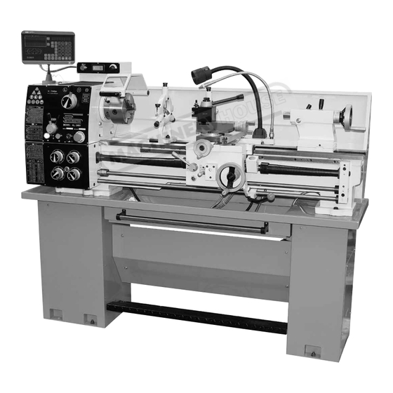
- Page 1 Page 1 Instructions Manual for AL-346V (L555D) 01/09/2017 INSTRUCTION MANUAL AL-346V Centre Lathe (240V) 330 x 1000mm Turning Capacity L555D...
- Page 2 Page 2 Instructions Manual for AL-346V (L555D) 01/09/2017 METAL LATHE INSTRUCTION MANUAL 2015/11/V.1...
-
Page 3: Table Of Contents
Page 3 Instructions Manual for AL-346V (L555D) 01/09/2017 TABLE OF CONTENTS TABLE OF CONTENTS cutting fluid system INTRODUCTION Steady rest & follow rest SECTION 1: SAFETY Tool post Safety instructions for machinery Spindle speed Additional safety for metal lathes Manual feed... -
Page 4: Introduction
Page 4 Instructions Manual for AL-346V (L555D) 01/09/2017 INTRODUCTION Manual accuracy We are proud to offer this manual with your new machine! We've made every effort to be exact with the instructions, specifications, drawings, and photographs of the machine we used when writing this manual. However, sometimes we still make an occasional mistake. - Page 5 Page 5 Instructions Manual for AL-346V (L555D) 01/09/2017 Technical parameter MAX. Swing over bed---------------------------------------------------------------------------------------------330mm (13 " ) MAX. Swing over cross slide---------------------------------------------------------------------------------------198mm (7.8 ") MAX. Swing over gap--------------------------------------------------------------------------------------------17.71 " (450mm) MAX. Distance between centers-------------------------------------------------------------------------------1000mm (39.4 ") Bed width------------------------------------------------------------------------------------------------------------181mm (7.08 " ) Spindle bore----------------------------------------------------------------------------------------------------------40mm (1.574 "...
-
Page 6: Section 1: Safety
Page 6 Instructions Manual for AL-346V (L555D) 01/09/2017 SECTION 1: SAFETY For your own safety, read instruction manual before operating this machine DANGER! Indicates an imminently hazardous situation which, if not avoided, will result in death or serious injury. WARNING! Indicates a potentially hazardous situation which, if not avoided, could result in death or serious injury. -
Page 7: Additional Safety For Metal Lathes
Page 7 Instructions Manual for AL-346V (L555D) 01/09/2017 15. Guards & covers. Guards and covers reduce accidental contact with moving parts or flying debris. Make sure they are properly installed, undamaged, and working correctly. 16. Forcing machinery. Do not force machine. It will do the job safer and better at the rate for which it was designed. -
Page 8: Additional Chuck Safety
Page 8 Instructions Manual for AL-346V (L555D) 01/09/2017 or with a rag. Use a brush or vacuum to clear metal chips. 8. Stopping spindle by hand. Stopping the spindle by putting your hand on the work piece or chuck creates an extreme risk of entanglement, impact, crushing, friction, or cutting hazards. -
Page 9: Section 2: Power Supply
Page 9 Instructions Manual for AL-346V (L555D) 01/09/2017 SECTION 2: POWER SUPPLY Availability Before installing the machine, consider the availability and proximity of the required power supply circuit. If an existing circuit does not meet the requirements for this machine, a new circuit must be installed. To minimize the... -
Page 10: Section 3: Setup
Page 10 Instructions Manual for AL-346V (L555D) 01/09/2017 SECTION 3:SETUP Preparation The list below outlines the basic process of preparing your machine for operation. Specific steps are covered later in this section. The typical preparation process is as follows: 1. Unpack the lathe and inventory the contents of the box/crate. -
Page 11: Site Considerations
Page 11 Instructions Manual for AL-346V (L555D) 01/09/2017 cleaner/degreaser, then let it soak for 5–10 minutes. 3. Wipe off the surfaces. If your cleaner/degreaser is effective, the rust preventative will wipe off easily. If you have a plastic paint scraper, scrape off as much as you can first, then wipe off the rest with the rag. -
Page 12: Lifting & Moving
Page 12 Instructions Manual for AL-346V (L555D) 01/09/2017 generally those where the ambient temperature range exceeds 41°–104°F(0°–40°C) ; The relative humidity range exceeds 20–95% (non-condensing); or the environment is subject to vibration, shocks, or bumps. Electrical Installation Place this machine near an existing power source. Make sure all power cords are protected from traffic, material handling, moisture, chemicals, or other hazards. -
Page 13: Adding Cutting Fluid
Page 13 Instructions Manual for AL-346V (L555D) 01/09/2017 Using machine mounts Using machine mounts, shown in Figure, gives the advantage of fast leveling and vibration reduction. The large size of the foot pads distributes the weight of the machine to reduce strain on the floor. -
Page 14: Installing V-Belts
Page 14 Instructions Manual for AL-346V (L555D) 01/09/2017 Installing V-Belts 1. Open end gear cover to expose pulleys. 2. Clean surfaces of pulleys, making sure to remove and oily residue from pulley sheaves Install tension V-belts (refer Tensioning/Replacing V-Belts on Page 35 in Owner’s Manual for detailed instructions) 4. -
Page 15: Section 4:Operation
Page 15 Instructions Manual for AL-346V (L555D) 01/09/2017 8. Move the feed direction lever (see Figure 2) to the disengaged middle position. 9. Turn the spindle speed control knob (Figure 2) all the way counterclockwise (lowest speed) to avoid possibility of a high-speed start. -
Page 16: Controls
Page 16 Instructions Manual for AL-346V (L555D) 01/09/2017 2. Examines the work piece to make sure it is suitable for turning, and then mounts the work piece required for the operation. 3. Mounts the tooling, aligns it with the work piece, and then adjusts it for a safe startup clearance. -
Page 17: Apron Controls
Page 17 Instructions Manual for AL-346V (L555D) 01/09/2017 lathe is safe for electrical work, general adjustments, or work piece changes. You must always disconnect the lathe from power before attempting any of these tasks. 04. Cutting fluid ON/OFF Switch: Toggles the cutting fluid pump ON or OFF. Never turn the cutting fluid pump on and let it run while the reservoir is empty, or pump damage may occur. - Page 18 Page 18 Instructions Manual for AL-346V (L555D) 01/09/2017 Cross Slide Handwheel Moves the cross slide in or out perpendicular to carriage travel and is equipped with a standard Dial. (Figure 5) Compound Slide Handwheel(Figure 5) Moves the compound and cutting tool relative to the workpiece at various angles with fine-depth control.
-
Page 19: Chuck & Faceplate Removal
Page 19 Instructions Manual for AL-346V (L555D) 01/09/2017 Chuck & faceplate removal/installation This lathe is shipped with a 3-jaw chuck installed, but some time you need to use a 4-jaw chuck or faceplate. The chucks and faceplate mount to the spindle with a camlock system, which uses a key to loosen and tighten camlocks for removal or installation (see Figure 8). - Page 20 Page 20 Instructions Manual for AL-346V (L555D) 01/09/2017 WARNING! Large chucks are very heavy. Always get assistance when removing or installing large chucks to prevent personal injury or damage to the chuck or lathe. 5. Use a rocking motion to carefully remove the chuck from the spindle (see Figure 12).
-
Page 21: Three-Jaw Chuck
Page 21 Instructions Manual for AL-346V (L555D) 01/09/2017 Figure 14 Three-Jaw chuck This section outlines basic operation safety related to using the 3-jaw chuck included with your lathe. Use knowledge of safety and common sense when applying the steps on how to use this chuck. If you have any questions, feel free to contact our technical support department. -
Page 22: Four-Jaw Chuck
Page 22 Instructions Manual for AL-346V (L555D) 01/09/2017 If the workpiece is not centered, loosen the jaws and adjust the workpiece, then re-tighten the jaws and repeat step5. if the workpiece is centered, fully tighten the jaws. Removing jaws 1. Disconnect the lathe from power. - Page 23 Page 23 Instructions Manual for AL-346V (L555D) 01/09/2017 area for clamping. If all four jaws cannot be used to hold the workpiece, you must use the faceplate for improved clamping options. Otherwise, a severe out-of-balance condition will be created. If spun even at an average speed, this chuck will almost always be out of balance, and the machinist and bystanders will be at risk of being hit with a thrown workpiece.
-
Page 24: Faceplate
Page 24 Instructions Manual for AL-346V (L555D) 01/09/2017 Faceplate This section outlines basic operation safety related to using the faceplate included with your lathe. Use knowledge of safety and common sense when applying the steps on how to use this faceplate. -
Page 25: Centers
Page 25 Instructions Manual for AL-346V (L555D) 01/09/2017 Centers Some time you need to use dead centers, live center, and adapter sleeve (see Figure 24) to adapt the centers into spindle bore. When installing centers verify that all mating surfaces are clean and free of nicks and burrs. -
Page 26: Tailstock
Page 26 Instructions Manual for AL-346V (L555D) 01/09/2017 Removing center from tailstock To remove a center, hold the end of the center with a rag to prevent it from falling, and reverse the handwheel until the center is pressed free. - Page 27 Page 27 Instructions Manual for AL-346V (L555D) 01/09/2017 3. Place the live center in your tailstock. 4. Attach a lathe dog at the spindle end to the bar stock from step 1, and mount it between the centers as shown in Figure 29.
-
Page 28: Cutting Fluid System
Page 28 Instructions Manual for AL-346V (L555D) 01/09/2017 Tip: When drilling or when tapping operations need to be done deep into a part, the quill can also be stabilized by slightly applying the lever to add drag and preload to the quill. -
Page 29: Tool Post
Page 29 Instructions Manual for AL-346V (L555D) 01/09/2017 The steady rest is clamped to the ways and supports the workpiece with three fingers at a single point between the chuck and the tailstock. The follow rest is bolted to the carriage and travels with it during turning or threading operations. Two fingers support the workpiece while the tool tip acts as the third support during cutting. -
Page 30: Spindle Speed
Page 30 Instructions Manual for AL-346V (L555D) 01/09/2017 Spindle speed Using the correct spindle speed is important for safe and satisfactory results, as well as maximizing tool life. To set the spindle speed for your operation, you will need to: (1) Determine the best spindle speed for the cutting task, and (2) configure the lathe controls to produce the required spindle speed. -
Page 31: Power Feed
Page 31 Instructions Manual for AL-346V (L555D) 01/09/2017 Power feed The feed selection lever (see Figure 38) allows the machinist to engage or disengage the apron for longitudinal or cross feeding tasks. Sometimes it is necessary to rock the carriage handwheel or the cross feed handwheel to assist in fully engaging the chosen feed gears. -
Page 32: Thread Settings
Page 32 Instructions Manual for AL-346V (L555D) 01/09/2017 4. The quick change gearbox there are four knobs, turn the first knob to “4” position, turn the second knob to “S” position, turn the third knob to “C” position and turn the fourth knob to “I” position. See Figure 40. - Page 33 Page 33 Instructions Manual for AL-346V (L555D) 01/09/2017 Feed direction lever Selects the direction for power feed.( See Figure 36). When lever is positioned to the right side, the carriage will move to the left along the bed, or the cross feed will travel toward the front of the lathe.
-
Page 34: Section 5:Maintenance
Page 34 Instructions Manual for AL-346V (L555D) 01/09/2017 When cutting inch threads, the thread dial must be disengaged from the leadscrew, and the half nut clamped to the leadscrew until the threads are complete. Otherwise the path of the same thread will be lost. All carriage returns for non-metric threads are made by backing the tool point out of the thread, and reversing spindle rotation with the spindle ON/OFF lever. -
Page 35: Oil Reservoirs
Page 35 Instructions Manual for AL-346V (L555D) 01/09/2017 Figure 48 Figure 49 Figure 50 Oil Reservoirs Checking & adding oil The headstock, gearbox, and apron have oil reservoirs that are equipped with sight glasses for quickly checking oil levels. Before and after every use, make sure that the oil levels are correct. Figures 51-56 show the gearbox locations of the sight glasses and the fill/drain plugs. - Page 36 Page 36 Instructions Manual for AL-346V (L555D) 01/09/2017 Headstock Drain Plug Headstock Fill Plug Figure 53 Figure 54 Headstock Gear Box Sight Glass Fill Plug Gear Box Gear Box Sight Glass Drain Plug Figure 55 Figure 56 Recommended oil types Headstock.....ISO 32#...
-
Page 37: V-Belt Tension
Page 37 Instructions Manual for AL-346V (L555D) 01/09/2017 To change the oil in the reservoirs: 1. Run the lathe to bring the lathe gearboxes to a warm temperature and turn OFF the lathe. 2. Disconnect lathe From power! 3. Remove the headstock gear cover. -
Page 38: Scetion 6: Service
Page 38 Instructions Manual for AL-346V (L555D) 01/09/2017 5. Inspect the cutting fluid quality as outlined by the fluid manufacturer and replace as recommended. Cleaning cutting fluid system 1. Place the drain hose on the end of the coolant nozzle, and pump the used cutting fluid into the drain bucket. - Page 39 Page 39 Instructions Manual for AL-346V (L555D) 01/09/2017 Operation and Work results - 37 -...
-
Page 40: Gib Adjustments
Page 40 Instructions Manual for AL-346V (L555D) 01/09/2017 Gib adjustments The cross-slide and compound slide on this lathe each use a long steel wedge called a gib that is positioned between the component and its dovetailed-ways. At the end of each gib is a gib screw one of which is shown in Figure 60. -
Page 41: Backlash Adjustment
Page 41 Instructions Manual for AL-346V (L555D) 01/09/2017 Saddle gib The saddle is supplied with a carriage lock on the front right-hand side of the slide (see Figure 62). This bolt locks the saddle in place for increased rigidity when making face cuts. -
Page 42: Half Nut Adjustment
Page 42 Instructions Manual for AL-346V (L555D) 01/09/2017 3. Rotate the cross slide handle clockwise to feed the leadscrew nut out from under the cross slide, as shown in Figure 65 4. Tighten the backlash adjustment cap screw shown in Figure 65 in small increments. -
Page 43: Tailstock Lock
Page 43 Instructions Manual for AL-346V (L555D) 01/09/2017 It is imperative to recognize however, the clutch is not a foolproof way of protecting your lathe from damage if an operational mistake is made, a chuck-carriage crash occurs, or general machine overloading occur on a regular basis. -
Page 44: Machine Storage
Page 44 Instructions Manual for AL-346V (L555D) 01/09/2017 Machine storage If the machine is not properly prepared for storage, it may develop rust or corrosion. Use the recommendations in this section to ensure that the lathe remains in good condition for later use. -
Page 45: Section 7:Parts List
Page 45 Instructions Manual for AL-346V (L555D) 01/09/2017 BED ASSEMBLY Index No Part No Description Size D330AV-11101 Lathe Bed GB/T5782-M12X40 Screw M12X40 D330A-11205 Rack Gear GB/T70-M6X15 Hex Socket Cap Screw M6X15 GB/T879-6X25 6X25 D330A-11204 Rack Gear GB/T97.1-12 Washer GB/T6170-M10 GB/T70-M10X35... - Page 46 Page 46 Instructions Manual for AL-346V (L555D) 01/09/2017 - 44 -...
-
Page 47: Head Stock
Page 47 Instructions Manual for AL-346V (L555D) 01/09/2017 HEAD STOCK-1 Index No Part No Description Size D330A-21107 Head Stock GB/T3452.1-20X2.65 Oil seal 20X2.65 D330A-21246 Sleeve D330A-21235 Sleeve GB/T819-M4X8 Screw M4X8 GB/T70-M6X40 Hex Socket Cap Screw M6X40 GB/T879-5X40 5X40 D330A-21113-2 Case frame... - Page 48 Page 48 Instructions Manual for AL-346V (L555D) 01/09/2017 Index No Part No Description Size GB77-M4X6 Screw M4X6 D330A-21102 Collar GB/T70-M6X25 Hex Socket Cap Screw M6X25 D330A-21103 End cover D330A-21603 Gasket GB/T297-30210/P5 Bearing 30210/P5 D330A-21207A Gear GB/T78-M4X10 Screw M4X10 GB/T6170-M4 D330AV-21227...
- Page 49 Page 49 Instructions Manual for AL-346V (L555D) 01/09/2017 - 47 -...
- Page 50 Page 50 Instructions Manual for AL-346V (L555D) 01/09/2017 HEAD STOCK-2 Index No Part No Description Size Hexagonal socket head M16X1.5 D330A-21112-1 Cover board D330A-21606 Gasket GB/T70-M6X25 Hex Socket Cap Screw M6X25 JB/T7941.2-M16X1.5 Oil sight M16X1.5 D330A-81201 Cam lock stud GB/T70-M6X12...
- Page 51 Page 51 Instructions Manual for AL-346V (L555D) 01/09/2017 GEAR BOX - 49 -...
- Page 52 Page 52 Instructions Manual for AL-346V (L555D) 01/09/2017 - 50 -...
- Page 53 Page 53 Instructions Manual for AL-346V (L555D) 01/09/2017 GEAR BOX Index No. Part No. Description Size Qty. D330A-3034 Cover D330A-3035 Oil seal D330A-3041 Shaft D330A-3005 Gear D330A-3066 Washer D330A-3067 Shaft GB894.1-20 Circlip D330A-3027 Gear D330A-3025 Gear D330A-3044 Cover D330A-3046 Oil seal...
- Page 54 Page 54 Instructions Manual for AL-346V (L555D) 01/09/2017 Index No. Part No. Description Size Q t y . D330A-GB812 D330A-3016 Gear D330A-3015 Shaft D330A-3014 Gear CQ6230-3086D Oil Seal CQ6230-3022F Cover CQ6230-3013D Shaft CQ6230-3011D Shaft D330A-3012 Position Piec CQ6230-3089A Shaft CQ6230-3049C...
- Page 55 Page 55 Instructions Manual for AL-346V (L555D) 01/09/2017 APRON - 53 -...
- Page 56 Page 56 Instructions Manual for AL-346V (L555D) 01/09/2017 APRON Index No Part No Description Size CQ6230-4001 Apron Casting GB/T5782-M8X30 Cap Screw M8X30 GB/T97.1-8 Washer GB/T1096-5X36 5X36 CQ6230-4008 Worm CQ6230-4009 Bracket CQ6230-4003 Half Nut Half Nut GB/T70-M6X40 Cap Screw M6X40 GB/T6175-M6...
- Page 57 Page 57 Instructions Manual for AL-346V (L555D) 01/09/2017 Index No Part No Description Size GB/T119-5X33 5X33 CQ6230-4013 Gear GB308---6 Steel Ball CQ6123-14-01 Sping GB/T77-M8X8 Screw M8X8 CQ6230-4015 Shaft CQ6230-4042 Gear CQ6230-4041 Lever CQ6230-4039 Bracket GB/T70-M6X45 Cap Screw M6X45 Bolt M10X1...
-
Page 58: Compound Rest
Page 58 Instructions Manual for AL-346V (L555D) 01/09/2017 COMPOUND REST - 56 -... - Page 59 Page 59 Instructions Manual for AL-346V (L555D) 01/09/2017 COMPOUND REST Index No Part No Description Size CQ6230-5010 Handle CQ6230-5009 Boss CQ6230-5008 Collar GB/T83-M10×45 Screw M10×45 CQ6230-5005 Tool Post CQ6230-5006 Shaft CQ6230-5003 CQ6230-5004 GB2089-1.2×6×8 Spring 1.2×6×8 JB/T7940.4-6 Oil cup D330A-S2003 Shaft GB/T78-M6×16...
- Page 60 Page 60 Instructions Manual for AL-346V (L555D) 01/09/2017 SADDLE - 58 -...
- Page 61 Page 61 Instructions Manual for AL-346V (L555D) 01/09/2017 SADDLE Index No Part No Description Size D330A-51101 Saddle GB818-M5X12 Screw M5X12 D330A-51301 Wipper D330A-51211 Cover GB/T879-3X10 3X10 D330A-51216 Press plate D330A-51303 Press plate D330A-51204 Wipper D330A-51215 Screw D330A-S1001 Screw GB/T118-6X45 Taper Pin 6X45 GB/T70-M10×30...
- Page 62 Page 62 Instructions Manual for AL-346V (L555D) 01/09/2017 TAILSTOCK - 60 -...
- Page 63 Page 63 Instructions Manual for AL-346V (L555D) 01/09/2017 TAILSTOCK Index No Part No Description Size CQ6230-4033 Handle CQ6230-4032 Lever GB/T77-M5X25 Screw M5X25 D330A-6044 Adjusting screw D330A-6045 Washer D330A-6005 Hand Wheel CQ6230-4037 Leaf Spring D330A-6010 Index Ring GB/T70-M6X16 Hex Socket Cap Screw...
- Page 64 Page 64 Instructions Manual for AL-346V (L555D) 01/09/2017 CHANGE GEAR Index No. Part No. Description Size Q t y . GB/T70-M6X12 Hex Socket Cap Screw M6X12 GB/T96-6 Washer D330A-91202 Gear GB/T1096-A5X8 A5X8 GB/T6175-M10 GB/T97.1-10 Washer D330A-91208 Gear 120/127T GB/T276-6003 Bearing...
-
Page 65: Control Switch Assembly
Page 65 Instructions Manual for AL-346V (L555D) 01/09/2017 CONTROL SWITCH ASSEMBLY - 63 -... - Page 66 Page 66 Instructions Manual for AL-346V (L555D) 01/09/2017 CONTROL SWITCH ASSEMBLY Index No Part No Description Size D330A-11201 Guide Screw D330A-11202 D330A-11102 Bracket GB/T118-6X45 Taper Pin 6X45 GB/T70-M8X60 Hex Socket Cap Screw M8X60 JB/T7940.4-6 Oil cup GB308---6 Ball GB/T78-M6×10 Screw M6×10...
-
Page 67: Bed And Drive Assembly
Page 67 Instructions Manual for AL-346V (L555D) 01/09/2017 BED AND DRIVE ASSEMBLY - 65 -... - Page 68 Page 68 Instructions Manual for AL-346V (L555D) 01/09/2017 BED AND DRIVE ASSEMBLY Index No Part No Description Size D330A-13401A-1 Cover D330A-13402A-1 Cover D330A-14220 Cover D330A-11107 Trestle GB/T97.1-10 Washer GB/T5782-M10X30 Screw M10X30 GB/T1096-8X35 8X35 D330A-11106 Pulley GB/T78-M6X8 Screw M6X8 Motor GB/T97.1-8...
- Page 69 Page 69 Instructions Manual for AL-346V (L555D) 01/09/2017 STAND/ COOLANT PUMP/LAMP - 67 -...
- Page 70 Page 70 Instructions Manual for AL-346V (L555D) 01/09/2017 - 68 -...
- Page 71 Page 71 Instructions Manual for AL-346V (L555D) 01/09/2017 STAND/ COOLANT PUMP/LAMP Index No Part No Description Size D330A-14205A-1 Chip guard GB/T97.1-6 Washer GB/T70-M6X10 Hex Socket Cap Screw M6X10 D330A-14203A-1 Oil pan GB/T70-M6X20 Hex Socket Cap Screw M6X20 D330A-71206-4 Bracket GB/T70-M5X15...
- Page 72 Page 72 Instructions Manual for AL-346V (L555D) 01/09/2017 - 70 -...
- Page 73 Page 73 Instructions Manual for AL-346V (L555D) 01/09/2017 ELECTRIC ASSEMBLY-1 Index No Part No Description Size Protective circuit breaker DZ47-63C3 1P Protective circuit breaker DZ47-63C16 2P Transformer JBK5-100VA-TH GB/T818-M4X6 Screw M4X6 Fixing Rail Clip Rubber Cushing D330AV-14102 Cover GB97.1-4 Washer GB/T70- M4×10...
- Page 74 Page 74 Instructions Manual for AL-346V (L555D) 01/09/2017 Index No Part No Description Size D330AV-14301 Electric Box D330AV-14303 Base GB/T70- M6X10 Hex Socket Cap Screw M6×10 Inverter D330AV-14302 Cover GB/T818-M6X10 Screw M6×10 Junction box 20 Seat GB818-M4X6 Screw M4X6 GB818-M4X12...
-
Page 75: Steady Rest
Page 75 Instructions Manual for AL-346V (L555D) 01/09/2017 STEADY REST - 73 -... - Page 76 Page 76 Instructions Manual for AL-346V (L555D) 01/09/2017 STEADY REST Index No Part No Description Size D330A-8205 Knob GB/T879-3X20 M6X8 D330A-8207 Collar D330A-8206 Pressing Lever D330A-8208 Pressing Collar D330A-8209 Pressing Base D330A-8204 Locking screw nut GB/T78-M6X10 Screw M6X10 D330A-8202 Upper Body GB/T79-M6×16...
-
Page 77: Follow Rest
Page 77 Instructions Manual for AL-346V (L555D) 01/09/2017 FOLLOW REST Index No Part No Description Size D330A-8205 Knob GB/T879-3X20 3X20 D330A-8207 Collar D330A-8304 Pressing Lever D330A-8303 Pressing Collar D330A-8209 Pressing Base D330A-8301 Body GB/T78-M6X10 Screw M6X10 GB/T70-M8×40 Hex Socket Cap Screw M8×40... - Page 78 Page 78 Instructions Manual for AL-346V (L555D) 01/09/2017 CHUCK SAFTY GUARD(Optional) Index No Part No Description Size GB/T6170-M6 GB/T79-M6 ×16 Screw M6 ×16 D330A-71101 Switch box GB/T70-M6× 45 Hex Socket Cap Screw M6× 45 D330A-71203 Shaft D330A-71204 Protecting Cover GB/T879-4X25...
- Page 79 Page 79 Instructions Manual for AL-346V (L555D) 01/09/2017 LEADSCREW SAFTY GUARD(Optional) Index No Part No Description Size D330A-1030 Bracket GB/T70-M5×10 Hex Socket Cap Screw M5×10 D330A-F7001 Spring cover D330A-1034 Left bracket GB/T70-M6×12 Hex Socket Cap Screw M6×12 D330A-1033 Bracket GB/T70-M4×10 Hex Socket Cap Screw M4×10...
- Page 80 Page 80 Instructions Manual for AL-346V (L555D) 01/09/2017 SAFTY CLUTCH FOR FEED ROD(Optional) Index No Part No Description Size D330A-3013S/01A Clutch GB/T308-6 Steel ball GB/T879-4X42 4X42 D330A-3020D-1 Clutch GB/T1358-6X1X25 Spring 6X1X25 GB/T77-M8X8 Screw M8X8 GB/T78-M6X10 Screw M6X10 D330A-CS004-1 Cover GB/T301-51104...
- Page 81 Page 81 Instructions Manual for AL-346V (L555D) 01/09/2017 QUICK CHANGE TOOL POST(Optional) Index No Part No Description Size Flange nut M16-2 Shaft bushing Tool post lever hub Handle Lever Body Hex nut M10-1 Wavy wash 10mm Flat wash 10mm Set screw...
- Page 82 Page 82 Instructions Manual for AL-346V (L555D) 01/09/2017 SADDLE POSITION LOCALIZER(Optional) Index No Part No Description Size D330A-DC003 Index ring GB/T879-3X6 D330A-DC004 Shaft GB/T79-M6X10 Screw M6X10 D330A-DC001 Casting body D330A-DC002 Plate GB/T70-M6X10 Hex Socket Cap Screw M6X10 GB/T79-M5X12 Screw M5X12...
Need help?
Do you have a question about the AL-346V and is the answer not in the manual?
Questions and answers