Advertisement
Quick Links
Start-up Procedures
Maintenance & Safety Inspections
Wiring Diagrams
Burner
Burner Start-up
Burner Troubleshooting
MXG Burner Manual
MXO Burner Manual
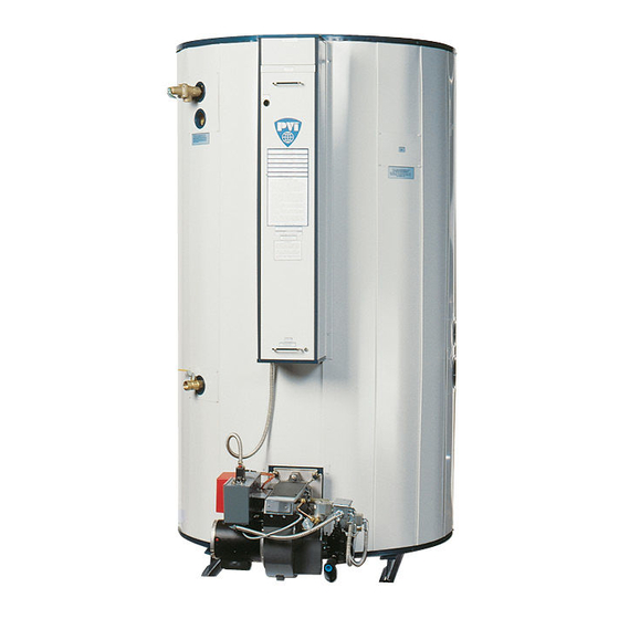
1. VENT STACK *
2. TEMPERATURE LIMITING DEVICE (set at 200°F)
3. OPERATING THERMOSTAT (set at 120°F)
4. CONTROL SWITCH(es) AND FUSE(s)
5. GAS VALVE
6. GAS INLET
7. BURNER
CAUTION: Temperatures higher than 130°F increase the risk of scald injury!
IMPORTANT! Clearance to unprotected combustible material must be 8" min. at top, sides and rear, and 24" min. in front.
PV500-17 05-2000
INSTALLATION & MAINTENANCE MANUAL FOR
MAXIM
INTEGRATED WATER HEATING SYSTEM
TABLE OF CONTENTS
TYPICAL CONSTRUCTION
FIGURE 17-1
MAXIM
8. HANDHOLE CLEANOUT
9. UPPER OPERATING THERMOSTAT (set at 130°F)
10. COLD WATER INLET & RETURN CONNECTION
11. DRAIN
12. RELIEF VALVE
13. PRIMARY SAFETY CONTROL
14. DIFFERENTIAL AIR PROVING SWITCH
1
2
3-5
6,7
8
9-12
13.14
Refer to PV500-21A
Refer to PV500-22A
FOR YOUR SAFETY
WHAT TO DO WHEN YOU
SMELL GAS:
DO NOT try to light
any appliance.
DO NOT touch any
electrical switch; DO NOT
use any phone in your
building.
IMMEDIATELY call
your gas supplier from a
phone outside the
building. Follow the gas
supplier's instructions.
If you cannot reach
your gas supplier, CALL
THE FIRE DEPARTMENT.
FOR YOUR SAFETY
DO NOT store or use gasoline or
other flammable vapors and
liquids in the vicinity of this or
any other appliance.
FOR YOUR SAFETY
WARNING: Improper
installation, adjustment,
alteration, service, or
maintenance can cause injury or
property damage. Refer to this
manual for assistance, or
consult a qualified installer,
service agency, or the gas
supplier.
(* NOT FURNISHED BY PVI)
Section 17
Advertisement

Subscribe to Our Youtube Channel
Summary of Contents for PVI MAXIM INTEGRATED WATER HEATING SYSTEM
- Page 1 INSTALLATION & MAINTENANCE MANUAL FOR INTEGRATED WATER HEATING SYSTEM Start-up Procedures Maintenance & Safety Inspections Wiring Diagrams Burner Burner Start-up Burner Troubleshooting MXG Burner Manual MXO Burner Manual 1. VENT STACK * 2. TEMPERATURE LIMITING DEVICE (set at 200°F) 3. OPERATING THERMOSTAT (set at 120°F) 4.
-
Page 2: Start-Up Procedures
COMBUSTION CHAMBER. Study the burner start-up information included in this manual carefully. Fill the water heater tank with water. Open the relief valve or a nearby hot water faucet to allow air in the tank to escape. Be sure all connections into the tank are tight as leaks at tank fittings will damage the insulation. - Page 3 MAINTENANCE AND SAFETY INSPECTIONS 1. Establish a preventive maintenance program to assure a longer water heater life. 2. The tank should be flushed at two- or three- month intervals depending on water conditions in your location. To flush, turn off electrical disconnect switch to prevent the burner from operating.
- Page 4 Since water Instructions for Taking Water Heater Out of Service Extended shutdown of the appliance and restarting are as follows: A. Turn off all power and fuel supplies.
- Page 5 MAINTENANCE & SAFETY INSPECTION REPORT BURNER COMBUSTION TANK TANK FLUSH TANK FITTING VENT THERMOSTAT GAS TRAIN DATE INSPECTION ANALYSIS INSPECTION & CLEANOUT INSPECTION INSPECTION INSPECTION LEAK TEST Recommended Inspection YEARLY 6 MONTHS 6 MONTHS 3 MONTHS 6 MONTHS YEARLY YEARLY YEARLY Intervals TABLE 17-1...
- Page 6 AXIAL FLOW GAS BURNER CARBON MONOXIDE WARNING: CAUTION: IMPROPER COMBUSTION MAY CAUSE SERIOUS INJURY. PVI recommends a seasonal or annual combustion check-out be performed by a qualified service agency to ensure safe and efficient operation. 1. FAN HOUSING 2. AIR DAMPER 3.
- Page 7 AXIAL FLOW GAS BURNER START-UP (Refer to Figure 17-2, page 6 to identify burner parts) Remove the enclosure panel cover on the water heater or boiler to expose the control circuit. A wiring diagram, included in this packet, will show the controls used in our circuitry.
-
Page 8: Pressure Plate
AXIAL FLOW GAS BURNER START-UP (continued) 13. Connect a test meter to the control for reading the flame response signal. NOTE: Some controls read the flame signal in micro amps and some in volts DC. The TFM or MC120 series control has two terminals marked for reading volts DC. - Page 9 AXIAL FLOW GAS BURNER START-UP (continued) This section pertains to MC120 control only. When the blower motor starts, the air proving light on the MC-120 should be on. This indicates a positive air flow condition. If the air proving light is not on, turn air proving switch adjustment screw counter-clockwise until the air proving light comes on, then turn screw one turn counter-clockwise.
- Page 10 AXIAL FLOW GAS BURNER START-UP (continued) 17. Check flue gases with a flue analyzer to make final settings of the air shutter. a. The readings need to be taken from a hole in the vent several inches above the heater vent connection, but before draft regulator.
- Page 11 1. BURNER FAILS TO START Defective On/Off switch. Replace switch. A. Control circuit has an open control contact. Check limits, low water cutoff, proof of closure switch and others as applicable. B. Bad fuse or switch open on incoming power source. Correct as required. C.
- Page 12 C. Defective automatic main or auxiliary gas shut off valves. Check electrical circuitry to valves. Replace valves or correct circuitry as required. D. Main diaphragm shut off valve opening too slowly. Adjust bleed on valve. E. Defective flame safeguard control or plug on amplifier.


Need help?
Do you have a question about the MAXIM INTEGRATED WATER HEATING SYSTEM and is the answer not in the manual?
Questions and answers