Advertisement
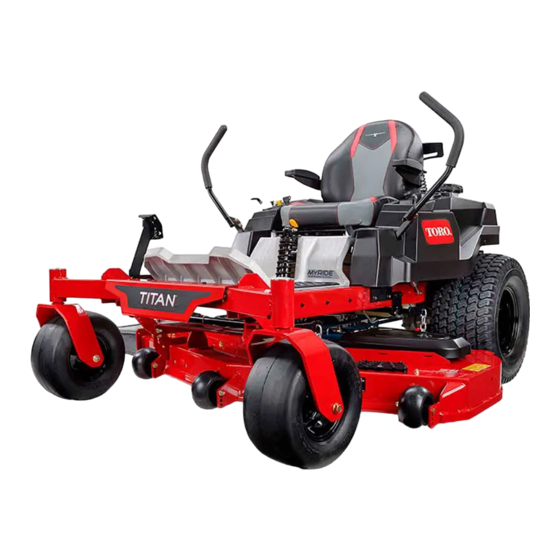
TITAN
Model No. All models
Setup
Loose Parts
Use the chart below to verify that all parts have been shipped.
Procedure
1
2
3
4
5
6
Note: Determine the left and right sides of the machine from the normal operating position.
© 2013—The Toro® Company
8111 Lyndale Avenue South
Bloomington, MN 55420
®
Riding Mower
Description
No parts required
Rear hitch
Bolt (5/16 x 2-1/2 inches)
Locknut (5/16 inch)
No parts required
No parts required
No parts required
Ignition key
Hose coupling (not included with CE
models)
Operator's Manual
Engine Operator's Manual
Operator training material
Register at www.Toro.com.
Form No. 3382-315 Rev A
Qty.
–
Connect the battery.
1
2
Install the rear hitch.
2
–
Set up the motion-control levers.
Set up the Rollover Protection System
–
(ROPS) bar.
–
Check the mower adjustment.
1
1
Complete the setup.
1
1
1
Original Instructions (EN)
All Rights Reserved *3382-315* A
Printed in the USA.
Setup Instructions
Use
Advertisement
Table of Contents

Subscribe to Our Youtube Channel
Related Manuals for Toro TITAN series


Summary of Contents for Toro TITAN series
-
Page 1: Loose Parts
Operator's Manual Engine Operator's Manual Operator training material Note: Determine the left and right sides of the machine from the normal operating position. © 2013—The Toro® Company Register at www.Toro.com. Original Instructions (EN) All Rights Reserved *3382-315* A 8111 Lyndale Avenue South Printed in the USA. -
Page 2: Connecting The Battery
Connecting the Battery Installing the Rear Hitch No Parts Required Parts needed for this procedure: Rear hitch Procedure Bolt (5/16 x 2-1/2 inches) 1. Locate the battery and negative battery cable. Locknut (5/16 inch) 2. Remove the plastic cap from the negative battery post. 3. - Page 3 Setting up the Motion-control Setting up the Rollover Levers Protection System (ROPS) Bar No Parts Required No Parts Required Procedure Procedure 1. Locate the motion-control levers attached, but folded 1. Remove the bolts (1/2 x 3 inches), washers, and nuts down on the machine.
-
Page 4: Completing The Setup
that the deck is level, and make any adjustments as necessary. Refer to the Operator's Manual for more information. Completing the Setup Parts needed for this procedure: Ignition key Figure 5 Hose coupling (not included with CE models) Left side shown; repeat on the right side Operator's Manual 1.
Need help?
Do you have a question about the TITAN series and is the answer not in the manual?
Questions and answers