Hurco winmax Getting Started Manual
Hide thumbs
Also See for winmax:
- Programming manual (184 pages) ,
- Programming manual (303 pages) ,
- Programming manual (254 pages)
Table of Contents
Advertisement
Quick Links
Download this manual
See also:
Programming Manual
Advertisement
Table of Contents

Subscribe to Our Youtube Channel
Related Manuals for Hurco winmax


Summary of Contents for Hurco winmax
- Page 1 ETTING TARTED WITH ATHE v546GS January 2017...
- Page 2 MS-DOS, Microsoft, and Windows are registered trademarks of Microsoft Corporation. Many of the designations used by manufacturers and sellers to distinguish their products are claimed as trademarks. Hurco has listed here all trademarks of which it is aware. For more information about Hurco products and services, contact: Hurco Companies, Inc.
-
Page 3: Table Of Contents
Consoles ..........1 - WinMax Interface Environment ....... . 1 - Edit Mode . - Page 4 Use the FTP Manager ........3 - v546GS iv - Table of Contents Getting Started—WinMax Lathe Max Control...
- Page 5 Program Parameters ........4 - 82 v546GS Table of Contents — v Getting Started—WinMax Lathe Max Control...
- Page 6 Entering the Access Code ......5 - 40 v546GS vi - Table of Contents Getting Started—WinMax Lathe Max Control...
- Page 7 Index ........... . v546GS Table of Contents — vii Getting Started—WinMax Lathe Max Control...
- Page 8 - viii Table of Contents Getting Started—WinMax Lathe Max Control...
-
Page 9: Documentation Conventions
Softkeys are located on the side of the screen. You can set the softkeys to appear on either the right or left side of the screen. Refer to the Getting Started with WinMax for information about making this selection. Softkeys may change upon field entries or other softkey selection. - Page 10 Manual key appears as the Manual console key in text. Refer to the Getting Started with WinMax manual for information about console buttons and keys, in addition to other information about using softkeys and the pop-up text entry window.
- Page 11 Ensures proper operation of the machine and control. Troubleshooting Steps that can be taken to solve potential problems. Hints and Tricks Useful suggestions that show creative uses of the WinMax features. Where can we go from here? Lists several possible options the operator can take. v546GS Documentation Conventions —...
-
Page 12: Programming And Operation Information
PERATION NFORMATION Hurco provides documentation for using WinMax software on a control or desktop in two formats: on-screen Help and PDF. The information contained in both formats is identical. On-screen Help contains information about the current screen. If Help is not available for a screen, a Welcome screen appears with access to the Table of Contents, Index, or Search functions. -
Page 13: Printing The Programming Manuals
Printing the Programming Manuals The WinMax On-screen Help is also provided in PDF format for easy printing. The information contained in the PDF files is identical to the on-screen Help. The PDF files may be copied to a floppy disk or USB memory device to be transferred to a PC for printing. - Page 14 - Programming and Operation Information Getting Started—WinMax Lathe Max Control...
- Page 15 Consoles ..........1 - WinMax Interface Environment........1 - Control Panel Function Groups .
-
Page 16: 1 - 2 Machine And Console Basics
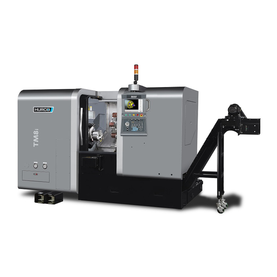
Machine Components Before using the machine, you should become familiar with its components. Because of European Committee (CE) requirements, Hurco machines sold in Europe may differ from those sold elsewhere. The figure below identifies some of the easily recognized components of a machine. The location of some components may differ on other models. -
Page 17: Turret
The optional Parts Catcher holds a part after it has been cut. You can open the Parts Catcher door to take the part out while the next part is being cut. Refer to WinMax Lathe Options Parts Catcher, on page 10 - 1 for information about this option. Refer to the Maintenance and Safety Manual for information about the pneumatic system maintenance for this option. -
Page 18: Bar Feeder
As the stock is cut, the feeder replaces it with a new piece as necessary. You can program a tool with a Bar Feed Block to pull the stock away from the feeder. Refer to WinMax Lathe Options Bar Feeder, on page 3 - 1 for information about this option. v546GS 1 - 4 Machine and Console Basics Getting Started—WinMax Lathe Max Control... -
Page 19: Consoles
PC. Only the parts of the Windows® operating system that are necessary to run Hurco CNCs are used. Customers are not permitted to install software on the WinMax control. Pictured below are the Max5 dual-, Max4 dual-, and Max4 single-screen consoles. -
Page 20: Winmax Interface Environment
See Edit Mode below for more information. Edit Mode Edit Mode is set in Utilities. Refer to User Interface Settings, on page 2 - 10. WinMax has two edit modes: •... -
Page 21: Full Precision Editing
Cancel. Do not use Full Precision Editing to change numbers that are automatically calculated by WinMax. These numbers are calculated to their 12-digit maximum accuracy and changing them could result in changes to other automatic calculations in the program. -
Page 22: Drop-Down Lists
Select the “-” to collapse (close) and hide the files and folders in a folder Figure 1–5. Example of Expand and Collapse Files v546GS 1 - 8 Machine and Console Basics Getting Started—WinMax Lathe Max Control... -
Page 23: Sorting And Resizing Columns
These pop-ups can also be closed by selecting the “X” in the upper right corner: Minimize Close Figure 1–8. Pop-up showing minimize and close icons v546GS Machine and Console Basics 1-9 Getting Started—WinMax Lathe Max Control... -
Page 24: Status Bar
Status Bar The Status Bar appears at the bottom of every WinMax screen. It displays the program name of the current active part program, a calculator icon, the current unit of measure (inch or mm), the keyboard icon, and the current time. When viewed on a Max console, all icons appear in the same status bar;... -
Page 25: Pop-Up Calculator
(e.g., after creating a program name). 4. Select the X located in the lower left corner of the text entry window to close the keyboard. v546GS Machine and Console Basics 1-11 Getting Started—WinMax Lathe Max Control... -
Page 26: On-Screen Help
• Use the Print button to print the current displayed Help topic, if a printer is attached and configured. See Accessing the WinMax Help in PDF format for printing, on page 1 - 13 for more information about printing. •... -
Page 27: Accessing The Winmax Help In Pdf Format For Printing
Accessing the WinMax Help in PDF format for printing The WinMax On-screen Help is also provided in PDF format for easy printing. The information contained in the PDF files is identical to the on-screen Help. The PDF files may be copied to a USB memory device to be transferred to a PC for viewing or printing. -
Page 28: Control Panel Function Groups
Control Panel Function Groups The buttons, keys, and dials on the console are grouped by their functions. Here are the control panel groups on a WinMax Lathe Max console: 1. Machine Control buttons 2. Axis and Spindle Control dials 3. Jog Control functions 4. - Page 29 Feed Hold button is pressed, and the yellow beacon flashes above the control. Figure 1–13. Input screen with Feed Hold and Emergency Stop icons v546GS Machine and Console Basics 1-15 Getting Started—WinMax Lathe Max Control...
-
Page 30: Axis And Spindle Control
Rapid Override at 100% - Turret rotates at approximately 83 RPM (Maximum Speed). • Rapid Override at 1% - Turret rotates at approximately 0.83 RPM (Minimum Speed). v546GS 1 - 16 Machine and Console Basics Getting Started—WinMax Lathe Max Control... - Page 31 Spindle Speed knobs: • S1—S3 Speed (concentric override knob)—the larger bottom knob controls the Main spindle; the smaller top knob controls the Sub spindle. • S2 Speed—controls the Live Tooling spindle. v546GS Machine and Console Basics 1-17 Getting Started—WinMax Lathe Max Control...
-
Page 32: Machine Operations
Conversational block.The spindle will continue running at the last programmed speed. Press the flashing Start Cycle button to resume the automatic machining operation and execute the next block. v546GS 1 - 18 Machine and Console Basics Getting Started—WinMax Lathe Max Control... -
Page 33: Coolant
Activates the primary coolant system when the machine is in Auto or Manual mode, and overrides a Coolant Auto operation. Pressing the Primary key a second time turns off this operation. v546GS Machine and Console Basics 1-19 Getting Started—WinMax Lathe Max Control... -
Page 34: Spindle
If you select a spindle for jogging then select to jog the C Axis, the spindle automatically stops. v546GS 1 - 20 Machine and Console Basics Getting Started—WinMax Lathe Max Control... -
Page 35: Turret
Turret plus key once changes the Active Tool from Tool 4 to Tool The Start Cycle button flashes when the Turret -/+ console key is pressed. Press the flashing button to manually move the turret. v546GS Machine and Console Basics 1-21 Getting Started—WinMax Lathe Max Control... -
Page 36: Jog Units
Other than the Emergency Stop button, the Jog Unit does not affect running programs. The Wireless Remote Jog Unit must be paired with the machine before first use. See Wireless Jog Unit Pairing, on page 1 - 54. v546GS 1 - 22 Machine and Console Basics Getting Started—WinMax Lathe Max Control... -
Page 37: Setting Jog Unit Parameters
Entering a negative value (e.g., -500) causes the spindle to reverse (turn counterclockwise) at that speed. • Rotary Jog Feed (for machines with rotary or swivel axes)—enter the jog feedrate in RPM. v546GS Machine and Console Basics 1-23 Getting Started—WinMax Lathe Max Control... -
Page 38: Max5 Remote Jog Units
Flashlight Handle Store Position Emergency Stop Stop Cycle Start Cycle Rapid Jog Rate Knob Feed Hold Flashlight On/Off Axis Select Knob Handwheel Multipliers Jog Feed Jog Handwheel v546GS 1 - 24 Machine and Console Basics Getting Started—WinMax Lathe Max Control... -
Page 39: Premium Remote Jog Unit
(Premium and Wireless) Stop Cycle Start Cycle Rapid Jog Rate Knob Feed Hold Axis Select & Flashlight On/Off Override Knob feed rapid spindle Handwheel Multipliers Jog Feed Jog Handwheel v546GS Machine and Console Basics 1-25 Getting Started—WinMax Lathe Max Control... - Page 40 This is the view of the back of the Max5 Remote Jog Unit (both Basic and Premium): Enable button v546GS 1 - 26 Machine and Console Basics Getting Started—WinMax Lathe Max Control...
-
Page 41: Max4 Remote Jog Unit
1. Emergency Stop Button 2. Store Position Key 3. Hand Wheel Multiplier Keys 4. Jog Hand Wheel 5. Jog Feed Keys 6. Jog Feed Override 7. Axis Select Switch v546GS Machine and Console Basics 1-27 Getting Started—WinMax Lathe Max Control... -
Page 42: Remote Jog Units
S1, W, Y, C3, and S3 depending on the configuration. See Setting Jog Unit Parameters, on page 1 - 23 for instructions on setting the Jog Unit parameters. v546GS 1 - 28 Machine and Console Basics Getting Started—WinMax Lathe Max Control... - Page 43 One full turn equals 1 inch, or 25.4 mm). • Enable button—on machines with CE enabled, must be held to use the Start Cycle button and the +/- jog on the unit. v546GS Machine and Console Basics 1-29 Getting Started—WinMax Lathe Max Control...
-
Page 44: Enable Button
Enable button to jog the axes. It is not necessary to press and hold the Enable button to jog the axis using the hand wheel at x1, x10, or x100 speeds. v546GS 1 - 30 Machine and Console Basics Getting Started—WinMax Lathe Max Control... -
Page 45: Programming Keyboard
The right-hand pane lists the elements for the selected Profile data block. Jump to a desired block by selecting the block and pressing Enter. Figure 1–17. Program Review screen—Conversational Part Programming v546GS Machine and Console Basics 1-31 Getting Started—WinMax Lathe Max Control... - Page 46 For Numerical Control (NC) programs, the Review key displays the NC subroutines by number. Figure 1–18. Program Review screen—NC Programming v546GS 1 - 32 Machine and Console Basics Getting Started—WinMax Lathe Max Control...
- Page 47 • Aux/Menu—displays a pop-up menu for accessing functions for developing and managing programs. If using the WinMax Lathe Desktop software, select the F9 key to access this screen. Figure 1–19. Menu Console Key’s Pop-up selections A menu toolbar is also available by selecting anywhere on the status bar at the bottom of the screen.
-
Page 48: Standard Keys
• jump to the last visible line in the program on the NC Editor screen. v546GS 1 - 34 Machine and Console Basics Getting Started—WinMax Lathe Max Control... -
Page 49: Cursor Control Keys
Simulate Shift + left mouse click. • C (clear) console key—press to clear the value at the current cursor position. The C key works like an Esc key on a keyboard. v546GS Machine and Console Basics 1-35 Getting Started—WinMax Lathe Max Control... -
Page 50: Numeric Keypad
If the console is equipped with an AT-keyboard, it may be used to enter data into a field. Press the Enter key to update a field and advance the cursor. Press F1 through F8 to make softkey selections. v546GS 1 - 36 Machine and Console Basics Getting Started—WinMax Lathe Max Control... -
Page 51: Draw Key
Verify console key. Select the Draw F1 softkey to display or re-draw the graphic. Figure 1–22. Verification Graphics Screen For information on using graphics with part programs, see Verifying Part Programs— Graphics, on page 4 - 86. v546GS Machine and Console Basics 1-37 Getting Started—WinMax Lathe Max Control... -
Page 52: Communications Panel
Communications Panel Each Hurco machine may be connected to peripheral devices through a communications panel located on the machine’s electrical cabinet. Figure 1–23. Communications Panel Communication connectors may include a USB port, a serial port, and a network connector. •... -
Page 53: Utilities
Figure 2–1. Auxiliary Menu screen Use the softkeys on the Auxiliary Menu screen to navigate to other parts of WinMax Mill. This section describes the Edit Lockout Mode and the Utility Screen. Before using the Toggle Edit Lockout State for the first time, be sure to review Edit Lockout Mode—First Use, on page 2 - 14 and be... -
Page 54: Utility Screen
Log Files ..........2 - 28 Hurco recommends using the Shutdown Control command prior to turning off machine power to ensure that no data is lost. -
Page 55: System Configuration
When 0 is entered, the timer is off. In other words, there is no time out. • When a number from 1 to 600 is entered, that number represents the number of minutes the machine can sit idle before shutting off the control power. v546GS Utilities 2-3 Getting Started—WinMax Lathe Max Control... -
Page 56: Hour Meters
• MAIN SPINDLE ON TIME—displays how many hours, minutes, and seconds the main spindle has been run since the machine was commissioned. v546GS 2 - 4 Utilities Getting Started—WinMax Lathe Max Control... -
Page 57: Machine Internet Protocol Address
To access the Hardware Configuration softkey menu, select the HARDWARE CONFIGURATIONS F3 softkey on the System Configuration screen. This screen appears: Figure 2–5. Hardware Configurations screen v546GS Utilities 2-5 Getting Started—WinMax Lathe Max Control... -
Page 58: Tool Setter Calibration
Tool Setter Calibration Select the TOOL SETTER CALIBRATION F1 softkey on the Hardware Configurations screen to configure the Tool Setter option. Refer to WinMax Lathe Options Tool Setter, on page 16 - 1 for information about this feature. Figure 2–6. Tool Setter Calibration screen... - Page 59 • FORCE OUTPUT ON F4—the Output State on-screen LED turns green when this softkey is selected. • FORCE OUTPUT OFF F5—the Input State on-screen LED turns red when this softkey is selected. v546GS Utilities 2-7 Getting Started—WinMax Lathe Max Control...
-
Page 60: Software Options
2. From the System Configuration screen, select the BACKUP CONFIG FILES F6 softkey. When you copy a file using a storage device or network drive, a pop- up window appears for choosing the location for the files to be cop- ied. v546GS 2 - 8 Utilities Getting Started—WinMax Lathe Max Control... - Page 61 4. Remove the storage device when the restoration is complete, and store it in a safe location. If you use a network drive, be sure it is in a safe, secure location. v546GS Utilities 2-9 Getting Started—WinMax Lathe Max Control...
-
Page 62: User Preferences
The USER INTERFACE SETTINGS F1 softkey accesses a screen with the following fields. Change the screen appearance or behavior with the User Interface Settings selections. Figure 2–10. User Interface Settings screen v546GS 2 - 10 Utilities Getting Started—WinMax Lathe Max Control... - Page 63 The Show All File Types field must be set to YES in order to see the PDF files in the directory in which the Help documentation is stored. Please refer to Accessing the WinMax Help in PDF format for printing, on page 1 - 13 for information about printing the Help.
- Page 64 2 - 13 for a complete listing of features that are affected by partial and full lockout. You will be redirected to the Input screen if you are on a screen that becomes locked out when you enter the password. v546GS 2 - 12 Utilities Getting Started—WinMax Lathe Max Control...
-
Page 65: User Preferences
Program Parameters. Since Program Parameters are not accessible in Partial or Full lockout mode, Feed Override Lockout should be set to YES so overrides cannot be adjusted while running the program. v546GS Utilities 2-13 Getting Started—WinMax Lathe Max Control... -
Page 66: Edit Lockout Mode-First Use
4. Select the User Interface Settings softkey. The User Interface Settings screen appears. When the cursor is in the Edit Lockout Level field, the Change Lockout Password softkey is available. Figure 2–11. User Interface Settings, Change Lockout Password softkey v546GS 2 - 14 Utilities Getting Started—WinMax Lathe Max Control... -
Page 67: Enable Edit Lockout Mode
2. Enter the password and select OK. The Edit Lockout feature is disabled, and a confirmation message appears. Please refer to Setting Edit Lockout Level Preferences, on page 2 - 14 for details about Partial and Full lockout levels. v546GS Utilities 2-15 Getting Started—WinMax Lathe Max Control... -
Page 68: Conversational Settings
• If a field contains a value of 5 and you type “2-” the 5 changes to “2” because the control expects a second value to be subtracted from 2. v546GS 2 - 16 Utilities Getting Started—WinMax Lathe Max Control... -
Page 69: Nc Settings
ENABLE GOUGE DETECTION—select Yes or No to enable gouge protection when running NC programs. This field is available for ISNC. • M-CODE TRANSLATION MAP Softkey—opens M-Code Translation Map table. See M Code Translation, on page 5 - 2. v546GS Utilities 2-17 Getting Started—WinMax Lathe Max Control... -
Page 70: Autosave Settings
AutoSave does not save a program to its original program name or drive. Refer to Save Files, on page 3 - 5 for instructions on saving a program. v546GS 2 - 18 Utilities Getting Started—WinMax Lathe Max Control... -
Page 71: Select Language
Current Language field. Language Quick Toggle You can toggle between two languages from any screen in WinMax using the Language Quick Toggle feature. To set the primary and secondary languages, highlight a language in the list and select the Set as Toggle Language 1 softkey (for primary language) or Set as Toggle Language 2 softkey (for secondary language). -
Page 72: Data Logging Filters
When NO is selected in the Enable Data Logging field, none of the filter selections are active. NO is the default. This field resets to NO each time the WinMax software restarts. Select YES and the message “Warning: Enabling data logging will reduce performance.”... -
Page 73: Serial Port Settings
XON/XOFF—identifies the protocol using a software flow control method. • FULL HANDSHAKE—identifies the protocol using a software flow control method similar to XON/XOFF. The difference lies in the synchronization stage of Full Handshake. v546GS Utilities 2-21 Getting Started—WinMax Lathe Max Control... -
Page 74: Ftp Server Settings
F7 softkey to access the FTP SERVER SETTINGS F2 softkey and the FTP Server Settings screen. Figure 2–18. FTP Server Settings screen Refer to WinMax Lathe Options UltiMonitor, on page 17 - 1 for information about this option. v546GS 2 - 22 Utilities... -
Page 75: Mmi Uptime
(D), hours (H), minutes (M) and seconds (S) for machine power on. Refer to Power Up, on page 5 - 2 for more information about machine and control power. Figure 2–19. Uptime screen v546GS Utilities 2-23 Getting Started—WinMax Lathe Max Control... -
Page 76: Printing
PROGRAM PARAMETERS • PART SETUP • TOOL SETUP • WEAR OFFSETS • GEOMETRY OFFSETS • PRINT SIZE—move the slider from SMALL to LARGE to adjust the size of the printed text. v546GS 2 - 24 Utilities Getting Started—WinMax Lathe Max Control... -
Page 77: Integrator Support Services
Figure 2–21. Print Preview screen Integrator Support Services The Integrator Support Services screen is for Hurco Certified Technicians use only in configuring and setting up the machine. This screen is password protected. Unauthorized access to this area and changing machine settings may result in improper machine operation and/or damage to the machine. -
Page 78: Restart Control
The Restart Control command will remove control power, save all open programs in Project Manager based upon the last time AutoSave was performed for each open program, complete an orderly shutdown of the WinMax Lathe Max control, and then restart. -
Page 79: Serial I/O
FROM PORT and READ CONV FROM PORT to identify the program format to read. • BEGIN WRITING TO PORT1 F2—writes the program to the port. • ABORT PORT OPERATION F3—halts the read or write operation for the port. v546GS Utilities 2-27 Getting Started—WinMax Lathe Max Control... -
Page 80: Log Files
History screen. This list includes a date, time, filename and description for each status message. PREVIOUS PAGE F1 and NEXT PAGE F2 softkeys become available for accessing multiple page lists. A CLEAR ALL F4 softkey clears the list. v546GS 2 - 28 Utilities Getting Started—WinMax Lathe Max Control... -
Page 81: Retrieving Log Files
The Log files reside in the Part Programs (D) directory. 4. Navigate to the Significant Events folder following this path: Part Programs (D)/Hurco/WinMax/Output Files/Significant Events 5. Select the file(s) you wish to copy from the right-hand pane. 6. Select the Copy File(s) F2 softkey. - Page 82 2 - 30 Utilities Getting Started—WinMax Lathe Max Control...
-
Page 83: Project Manager
This section explains how to create and manage files and directories, set program properties, use File Manager, and access the UltiMonitor option using FTP Manager. Refer to WinMax Lathe Options UltiMonitor, on page 17 - 1 for details about UltiNet. The following topics are explained in this section: Overview . -
Page 84: Overview
Subdirectories are the folders inside a drawer, or a drive. Folders and files are stored in the cabinet drawers. Part programs are like individual sheets of paper that are stored loosely on the drives or inside folders. Figure 3–1. Directory Structure v546GS 3 - 2 Project Manager Getting Started—WinMax Lathe Max Control... -
Page 85: Managing Program Files
Project Manager icon to access this screen. Figure 3–2. Project Manager screen For detailed information about NC programming, refer to WinMax Lathe NC Programming Overview, on page 1 - 1 A lock icon appears between the program name and path name when the file is in use on a network. -
Page 86: Create A New File
Selecting a heading a second time inverts the order. For example, the alphabetical order for files sorted from A to Z will be sorted from Z to A with the second click of the heading. v546GS 3 - 4 Project Manager Getting Started—WinMax Lathe Max Control... -
Page 87: Save Files
1. Highlight the appropriate folder. folder will reside. 2. Select CREATE FOLDER F4. 2. Enter a file name. 3. Enter the folder name in the pop-up 3. Select SAVE F1. window and select OK. v546GS Project Manager 3-5 Getting Started—WinMax Lathe Max Control... -
Page 88: Close A File
PATH—displays the path to the saved file. This field is read-only. To change the path for the saved file, select the EXIT F8 softkey followed by the SAVE AS F4 softkey. v546GS 3 - 6 Project Manager Getting Started—WinMax Lathe Max Control... -
Page 89: Use File Manager
“Continue with delete operation?” If you are sure that you want to delete the folder, select OK. If you do not wish to delete the folder, select Cancel. v546GS Project Manager 3-7 Getting Started—WinMax Lathe Max Control... -
Page 90: Files
• FTP MANAGER F7—accesses the FTP Manager softkey menu. On the Project Manager screen, the FTP MANAGER softkey is F8. Refer to WinMax Lathe Options for details about the UltiMonitor option. • EXIT F8—returns to the Project Manager screen... -
Page 91: Use The Ftp Manager
Use the FTP Manager FTP (File Transfer Protocol) is a method of transferring files from one computer to another using the Internet and access the UltiMonitor option. Refer to WinMax Lathe Options UltiMonitor, on page 17 - 1 for details about UltiNet. - Page 92 3 - 10 Project Manager Getting Started—WinMax Lathe Max Control...
-
Page 93: Programming Basics
Programming Training........4 - 91 v546GS Programming Basics 4-1 Getting Started—WinMax Lathe Max Control... -
Page 94: Part Programming
NC Programing Overview, on page 1 - 1, Importing and Exporting M Code Data, on page 1 - 29, M Code Translation, on page 5 - 2, and WinMax Lathe Options, NCPP Variables, on page 8 - 2 for information about their functions. - Page 95 The following diagram shows how the software is set up, starting with the Input screen, accessing Part Setup F1, Tool Setup F2, Part Programming F3 for programming Data blocks, Program Parameters F4, and Project Manager F8. Figure 4–2. WinMax Lathe Programming diagram v546GS Programming Basics 4-3...
- Page 96 Exit F8 to New Block screen Transfer F5 (TMX MYS machines only) Move Tailstock F5 (TM12 and TM18 machines only) Exit F8 to Input Screen Table 4–1. Types of Data Blocks v546GS 4 - 4 Programming Basics Getting Started—WinMax Lathe Max Control...
-
Page 97: Planning
Radial and axial tools are used for live tooling. • Radial tooling approaches the stock in the -X axis direction. • Axial tooling approaches the stock in the -Z axis direction. v546GS Programming Basics 4-5 Getting Started—WinMax Lathe Max Control... -
Page 98: Setup Screens
Refer to Axis and Spindle Control, on page 1 - 16 for information about axis controls. Part and Tool Setup information is saved with conversational programs but not with NC programs. v546GS 4 - 6 Programming Basics Getting Started—WinMax Lathe Max Control... -
Page 99: Part And Tool Loading
Chuck Operations, on page 5 - 48 for information about operating the chuck. Loading Live Tooling Tool Holders Hurco TMM, TMX MY, and TMX MYS Series turning centers use tool holders mounted in turret turning stations to hold tools. Each tool holder must be inserted into the turret. -
Page 100: Loading Tools
Loading Tools Hurco turning centers use a turret to hold tools. Each tool is manually inserted into the turret. There are multiple turning center configurations: • Two Axis (TM series) • Live Tooling (TMM series) • Two Axis with Programmable Tailstock (TMX series) •... -
Page 101: Load Tools In Turret And Assign Tool Numbers
11 station 12 station 1 station 2 station 3 The Index Turret Forward example applies to 12 station turning centers. For 10 station turning centers, station 1 follows station 10. v546GS Programming Basics 4-9 Getting Started—WinMax Lathe Max Control... - Page 102 3 Move the turret in the most efficient manner, keeping in mind the length of tools and how moving the turret will affect their position during each index. v546GS 4 - 10 Programming Basics Getting Started—WinMax Lathe Max Control...
-
Page 103: Part Setup-Work Offsets
The Change Part Setup data block can be used to insert changes in part setup information within a part program. For information about this type of data block, refer to WinMax Lathe Conversational Part Programming, Change Part Setup, on page 2 - 195. - Page 104 • • • • • • • • • • • • • TMX MY • • • • • TMX MYS Table 4–2. Part Setup—Work Offsets machine configurations v546GS 4 - 12 Programming Basics Getting Started—WinMax Lathe Max Control...
- Page 105 10. Definitions for the fields and softkeys are located in these sections: Part Setup Fields, on page 4 - 14 and Part Setup Softkeys, on page 4 - 16. v546GS Programming Basics 4-13 Getting Started—WinMax Lathe Max Control...
-
Page 106: Part Setup Fields
Zero as shown in Figure 4–7. Part Offset Relative to Machine Zero, on page 4 - 11. This field is available for Two-Axis Programmable Tailstock (TMX series) turning centers only. v546GS 4 - 14 Programming Basics Getting Started—WinMax Lathe Max Control... - Page 107 ACTIVE OFFSET—contains the index value (1 – 99) specifying which offset is active. You can also define a new Active Offset by inserting a Change Part Setup data block within your part program. Refer to WinMax Lathe Conversational Programming, Change Part Setup, on page 2 - 195 for details.
-
Page 108: Part Setup Softkeys
EXIT F8 —exits the Table Commands menu and returns to the first Part Setup - Work Offsets menu. • EXIT F8 —exits the part setup process and returns to the Input screen. v546GS 4 - 16 Programming Basics Getting Started—WinMax Lathe Max Control... -
Page 109: Tool Setup-Geometry Offsets
Either press the Aux/Menu console key or the Input console key followed by the TOOL SETUP F2 softkey to access the Tool Setup screen and softkey menu. You can also use the menu toolbar and select the Tool icon to access this screen. v546GS Programming Basics 4-17 Getting Started—WinMax Lathe Max Control... - Page 110 # field, the software uses the Tool number as the Station number. If a tool is not assigned to a valid station number when you run the program, an error message appears on the screen. v546GS 4 - 18 Programming Basics Getting Started—WinMax Lathe Max Control...
- Page 111 The End console key jumps to the last tool in the program. The Page Up console key jumps to the previous tool in Tool Setup. The Page Down console key jumps to the next tool in Tool Setup. v546GS Programming Basics 4-19 Getting Started—WinMax Lathe Max Control...
-
Page 112: Turning Tool Setup Fields
Inserted Drill ..........4 - 44 Please refer to Live-Tooling Tool Setup Fields, on page 4 - 47 for information about Turning Tool setup. v546GS 4 - 20 Programming Basics Getting Started—WinMax Lathe Max Control... -
Page 113: Custom
Select the MORE F7 softkey followed by the SPEED AS CSS F1 softkey for the Feet or Meters per Minute value. Select the MORE F7 softkey followed by the SPEED AS RPM F2 softkey for the Revolutions per Minute value. v546GS Programming Basics 4-21 Getting Started—WinMax Lathe Max Control... - Page 114 INSERT HEIGHT—identifies the height of the insert when Parallelogram or Rectangle is the Insert Shape. There are no size, length, or height fields when Round is the Insert Shape. v546GS 4 - 22 Programming Basics Getting Started—WinMax Lathe Max Control...
-
Page 115: Turning
Geometry Offsets. This field is read-only and can only be edited from the Radius field in the Geometry Offset screen. Refer to Select a Radius, on page 4 - 73 for information about changing this entry. v546GS Programming Basics 4-23 Getting Started—WinMax Lathe Max Control... - Page 116 A graphical representation of the insert appears on the screen. Here are some examples of the available shapes: Diamond - 80° Square - 90° Triangle - 60° Round Parallelogram - 82° Figure 4–13. Sample Insert Shapes—Turning Tool Setup v546GS 4 - 24 Programming Basics Getting Started—WinMax Lathe Max Control...
-
Page 117: Boring
COMMENT—allows you to enter up to 20 characters to help describe the tool. This field does not affect the part program. You can use either the programming keypad, the pop-up text window, or the optional keyboard to enter characters. v546GS Programming Basics 4-25 Getting Started—WinMax Lathe Max Control... - Page 118 Primary coolant will be enabled whenever this tool is used if the Auto Coolant LED is on and OFF is not selected in the COOLANT field. v546GS 4 - 26 Programming Basics Getting Started—WinMax Lathe Max Control...
- Page 119 Figure 4–16. Positive and Negative Lead Angle examples—Boring Tool Setup v546GS Programming Basics 4-27 Getting Started—WinMax Lathe Max Control...
-
Page 120: Center Drill
• IPM—Inches per Minute. • MMPM—Millimeters Per Minute. The value for the Feed (IPM) or (MMPM) is calculated by the control using the Speed and Feed Per Rev field. v546GS 4 - 28 Programming Basics Getting Started—WinMax Lathe Max Control... -
Page 121: Drill
MAX X OFFSET—identifies the maximum amount a tool can be offset from the spindle center line when boring a hole with a drill. This is useful for cases where you need to bore a hole larger than the tool diameter. v546GS Programming Basics 4-29 Getting Started—WinMax Lathe Max Control... - Page 122 Selections for the Tool Tip Angle appear as softkey selections when the cursor is in this field. Figure 4–18. Tool Tip Angle and Tool Length fields—Drill v546GS 4 - 30 Programming Basics Getting Started—WinMax Lathe Max Control...
-
Page 123: Threading
Primary coolant will be enabled whenever this tool is used if the Auto Coolant LED is on and OFF is not selected in the COOLANT field. v546GS Programming Basics 4-31 Getting Started—WinMax Lathe Max Control... -
Page 124: Grooving
Geometry Offsets. This field is read-only and can only be edited from the Radius field in the Geometry Offset screen. Refer to Select a Radius, on page 4 - 73 for information about changing this entry. v546GS 4 - 32 Programming Basics Getting Started—WinMax Lathe Max Control... - Page 125 Primary coolant will be enabled whenever this tool is used if the Auto Coolant LED is on and OFF is not selected in the COOLANT field. v546GS Programming Basics 4-33 Getting Started—WinMax Lathe Max Control...
- Page 126 Figure 4–21. Illegal Orientation and Calibrated Corner example—Grooving Tool • TOOL WIDTH and TOOL LENGTH—enter the tool width and length in the fields that appear in the graphic. Figure 4–22. Width and Tool Length fields—Grooving Tool v546GS 4 - 34 Programming Basics Getting Started—WinMax Lathe Max Control...
-
Page 127: Cutoff
Select the MORE F7 softkey followed by the SPEED AS RPM F2 softkey for the Revolutions per Minute value. • Spindle Direction—identifies clockwise (CW) or counterclockwise (CCW) for the direction the tool will turn. The default is CW. v546GS Programming Basics 4-35 Getting Started—WinMax Lathe Max Control... - Page 128 Corner 1 at Upper Left Figure 4–23. Orientation and Calibrated Corner examples—Cutoff Tool If an illegal orientation is selected, the screen displays this image: Figure 4–24. Illegal Orientation and Calibrated Corner example—Cutoff Tool v546GS 4 - 36 Programming Basics Getting Started—WinMax Lathe Max Control...
-
Page 129: Back Turning
Geometry Offsets. This field is read-only and can only be edited from the Radius field in the Geometry Offset screen. Refer to Select a Radius, on page 4 - 73 for information about changing this entry. v546GS Programming Basics 4-37 Getting Started—WinMax Lathe Max Control... - Page 130 A graphical representation of the insert appears on the screen. Here are some examples of the available shapes: Diamond - 80° Square - 90° Triangle - 60° Round Parallelogram - 82° Figure 4–26. Sample Insert Shapes—Back Turning Tool Setup v546GS 4 - 38 Programming Basics Getting Started—WinMax Lathe Max Control...
-
Page 131: Back Boring
COMMENT—allows you to enter up to 20 characters to help describe the tool. This field does not affect the part program. You can use either the programming keypad, the pop-up text window, or the optional keyboard to enter characters. v546GS Programming Basics 4-39 Getting Started—WinMax Lathe Max Control... - Page 132 Primary coolant will be enabled whenever this tool is used if the Auto Coolant LED is on and OFF is not selected in the COOLANT field. v546GS 4 - 40 Programming Basics Getting Started—WinMax Lathe Max Control...
- Page 133 Figure 4–29. Positive and Negative Lead Angle examples—Back Boring Tool Setup v546GS Programming Basics 4-41 Getting Started—WinMax Lathe Max Control...
-
Page 134: Tap
IPM—Inches per Minute. • MMPM—Millimeters Per Minute. The value for the Feed (IPM) or (MMPM) is calculated by the control using the Speed and either the Pitch or TPI field. v546GS 4 - 42 Programming Basics Getting Started—WinMax Lathe Max Control... -
Page 135: Ream
• SPEED (RPM)—identifies the Revolutions per Minute (RPM) value for this tool. • Spindle Direction—identifies clockwise (CW) or counterclockwise (CCW) for the direction the tool will turn. The default is CW. v546GS Programming Basics 4-43 Getting Started—WinMax Lathe Max Control... -
Page 136: Inserted Drill
COMMENT—allows you to enter up to 20 characters to help describe the tool. This field does not affect the part program. You can use either the programming keypad, the pop-up text window, or the optional keyboard to enter characters. v546GS 4 - 44 Programming Basics Getting Started—WinMax Lathe Max Control... - Page 137 Inches or Millimeters per Minute feed rate. Select the MORE F7 softkey followed by the FEED PER REVOLUTION F5 softkey for the Inches or Millimeters per Revolution feed rate. • TOOL LENGTH—identifies the length of the tool. v546GS Programming Basics 4-45 Getting Started—WinMax Lathe Max Control...
- Page 138 Figure 4–33. Positive and Negative Lead Angle examples—Inserted Drill Tool Setup v546GS 4 - 46 Programming Basics Getting Started—WinMax Lathe Max Control...
-
Page 139: Live-Tooling Tool Setup Fields
Radius field in the Geometry Offset screen. Refer to Select a Radius, on page 4 - 73 for information about changing this entry. v546GS Programming Basics 4-47 Getting Started—WinMax Lathe Max Control... - Page 140 FLUTES—identifies the number of cutting flutes for the tool. This entry will be used to automatically calculate the mill feed in all data blocks for this part program using this tool. v546GS 4 - 48 Programming Basics Getting Started—WinMax Lathe Max Control...
- Page 141 Speed and Feed Per Rev field. • L—enter the length of the tool. When the cursor is in this field, the graphic changes to define what is meant by length. Figure 4–35. Tool Length field—End Mill v546GS Programming Basics 4-49 Getting Started—WinMax Lathe Max Control...
-
Page 142: Ball End Mill
Be aware of the length of radial tools. Radial tools that are too long can interfere with the Z-axis way cover when indexing the turret. Be aware of the tool orientation direction when using the Sub-spindle on TMX MYS machines. v546GS 4 - 50 Programming Basics Getting Started—WinMax Lathe Max Control... - Page 143 Be aware of the length of radial tools. Radial tools that are too long can interfere with the Z-axis way cover when indexing the turret. Be aware of the tool orientation direction when using the Sub-spindle on TMX MYS machines. v546GS Programming Basics 4-51 Getting Started—WinMax Lathe Max Control...
-
Page 144: Bull Nose Mill
Z axis. selected. Reset the orientation from the Orientation pop-up window in Tool Geometry Offsets. Figure 4–38. Live Tooling Orientation examples—Bull Nose Mill Tool Setup v546GS 4 - 52 Programming Basics Getting Started—WinMax Lathe Max Control... - Page 145 L—enter the length of the tool. When the cursor is in this field, the graphic changes to define what is meant by this length. Figure 4–39. Tool Length field—Bull Nose Mill v546GS Programming Basics 4-53 Getting Started—WinMax Lathe Max Control...
-
Page 146: Live Center Drill
Radius field in the Geometry Offset screen. Refer to Select a Radius, on page 4 - 73 for information about changing this entry. v546GS 4 - 54 Programming Basics Getting Started—WinMax Lathe Max Control... - Page 147 COOLANT field. • FEED PER REV—identifies the Feed per Revolution. The value for the Feed (IPM) or (MMPM) is calculated by the control using the Speed and Feed Per Rev field. v546GS Programming Basics 4-55 Getting Started—WinMax Lathe Max Control...
-
Page 148: Live Drill
TYPE—identifies the tool type to use for this tool number. The tool type determines the parameters required to define each tool. Select a tool type from the choices listed in this field. Select the down arrow to expand the list. v546GS 4 - 56 Programming Basics Getting Started—WinMax Lathe Max Control... - Page 149 SURFACE SPEED (FPM) or SURFACE SPEED (MPM)—identifies the surface speed per minute. When a value is entered in this field, the control automatically calculates the value for the SPEED field. • FPM—Feet per Minute. • MPM—Meters per Minute. v546GS Programming Basics 4-57 Getting Started—WinMax Lathe Max Control...
-
Page 150: Live Tap
TYPE—identifies the tool type to use for this tool number. The tool type determines the parameters required to define each tool. Select a tool type from the choices listed in this field. Select the down arrow to expand the list. v546GS 4 - 58 Programming Basics Getting Started—WinMax Lathe Max Control... - Page 151 Primary coolant will be enabled whenever this tool is used if the Auto Coolant LED is on and OFF is not selected in the COOLANT field. v546GS Programming Basics 4-59 Getting Started—WinMax Lathe Max Control...
-
Page 152: Live Ream
Be sure to verify Geometry and Wear Offsets for the tool. Refer to Tool Geometry Offsets, on page 4 - 67 and Tool Wear Offsets, on page 4 - 74 for details about these offsets. v546GS 4 - 60 Programming Basics Getting Started—WinMax Lathe Max Control... - Page 153 Primary coolant will be enabled whenever this tool is used if the Auto Coolant LED is on and OFF is not selected in the COOLANT field. v546GS Programming Basics 4-61 Getting Started—WinMax Lathe Max Control...
-
Page 154: Live Custom
Be sure to verify Geometry and Wear Offsets for the tool. Refer to Tool Geometry Offsets, on page 4 - 67 and Tool Wear Offsets, on page 4 - 74 for details about these offsets. v546GS 4 - 62 Programming Basics Getting Started—WinMax Lathe Max Control... - Page 155 Primary coolant will be enabled whenever this tool is used if the Auto Coolant LED is on and OFF is not selected in the COOLANT field. v546GS Programming Basics 4-63 Getting Started—WinMax Lathe Max Control...
- Page 156 TA—enter the angle of the tool tip. When the cursor is in this field, the graphic changes to define what is meant by this angle. Figure 4–54. Tool Tip Angle field—Live Custom v546GS 4 - 64 Programming Basics Getting Started—WinMax Lathe Max Control...
-
Page 157: Tool Setup Softkeys
WEAR OFFSETS F4—displays the Tool Wear Offsets screen. Refer to Tool Wear Offsets, on page 4 - 74 for details about this screen. • DELETE TOOL F5—deletes all program settings for the tool number entered in the Tool field. v546GS Programming Basics 4-65 Getting Started—WinMax Lathe Max Control... - Page 158 EXIT F8—exits the second softkey menu and returns to the first menu or exits the tool setup process from the first softkey menu and returns to the Input screen. v546GS 4 - 66 Programming Basics Getting Started—WinMax Lathe Max Control...
-
Page 159: Tool Geometry Offsets
Z-axis geometry offsets. Press the Store Position console key or select the softkey to store the offset in the Work Offset Z field. This selection is unavailable when Job Block Z is selected. v546GS Programming Basics 4-67 Getting Started—WinMax Lathe Max Control... -
Page 160: Tool Geometry Offsets Softkeys
Block Z or Work Offset Z) relative to the machine position. The cursor location defines which axis (X or Z) will be set. • TOOL SETTER F6—refer to WinMax Lathe Options, Tool Setter, on page 16 - 1 for information about this option. v546GS 4 - 68 Programming Basics Getting Started—WinMax Lathe Max Control... - Page 161 • More F7 —exits the menu and returns to the Tool Geometry Offsets menu. • EXIT F8 —exits the Tool Geometry Offsets menu and returns to the Tool Setup screen. v546GS Programming Basics 4-69 Getting Started—WinMax Lathe Max Control...
-
Page 162: Measuring Tool Offsets
X Offset—Measure from the turret face to the tip of the tool inserted in the tool holder. Figure 4–59. Turning tool and tool holder—Front (left) and Side (right) views v546GS 4 - 70 Programming Basics Getting Started—WinMax Lathe Max Control... - Page 163 Reference the tool manufacturer’s data sheet for the boring bar F-Dimension. Figure 4–60. Boring Bar tool and tool holder with F Dimension v546GS Programming Basics 4-71 Getting Started—WinMax Lathe Max Control...
- Page 164 Z Offset—Measure at the tool holder shank centerline = 0. X Offset—Measure from turret face to tip of tool inserted in the tool holder. Figure 4–62. Radial Live tool and tool holder v546GS 4 - 72 Programming Basics Getting Started—WinMax Lathe Max Control...
- Page 165 STORE POSITION F6 softkey. Repeat steps 2 through 5 for the Z axis. 6. Enter the appropriate Radius for this tool. 7. Select the ORIENTATION F3 softkey to select the orientation for this tool from the pop-up window. v546GS Programming Basics 4-73 Getting Started—WinMax Lathe Max Control...
-
Page 166: Tool Wear Offsets
X WEAR—displays the amount of tool wear in the X axis. • Z WEAR—displays the amount of tool wear in the Z axis. • RADIUS WEAR—displays the amount of tool wear in the Radius. v546GS 4 - 74 Programming Basics Getting Started—WinMax Lathe Max Control... -
Page 167: Tool Wear Offset Softkeys
F5 softkey for softkey choices to enter for the X, Z, or Radius offset. The choices are +0.0001 F1, +0.001 F2, +0.01 F3, -0.01 F4, -0.001 F5, and -0.0001 F6. v546GS Programming Basics 4-75 Getting Started—WinMax Lathe Max Control... -
Page 168: Automatic Feed And Speed Calculations
When performing a drilling operation, the control automatically calculates spindle speeds using this formula: When performing a drilling operation, the control uses this equation to calculate the feedrate: Feedrate = Feed Per Rev x RPM v546GS 4 - 76 Programming Basics Getting Started—WinMax Lathe Max Control... -
Page 169: Tool Review
2. Press the Insert key. The Tool Setup screen appears with the New Tool field. 3. Enter a number for the new tool and press Enter. The Tool Setup screen appears with fields for entering tool setup information for the new tool. v546GS Programming Basics 4-77 Getting Started—WinMax Lathe Max Control... -
Page 170: Edit From The Tool Review Screen
Cancel. You can also delete tools from the Tool Review screen using either the DELETE TOOL F4 softkey in the Multiple Tool Functions menu or the Delete key. v546GS 4 - 78 Programming Basics Getting Started—WinMax Lathe Max Control... - Page 171 • PART PROGRAMMING F3—accesses the Part Programming softkey menu. Refer to WinMax Lathe Conversational Part Programming for information about programming data blocks. • PART SETUP F4—accesses the Part Setup softkey menu. Refer to Part Setup—Work Offsets, on page 4 - 11 for information.
- Page 172 3. Press the DELETE F4 softkey. You can also delete tools directly from the Tool Review screen using the DELETE TOOL F2 softkey or the Delete key. 4. Save the revised program. v546GS 4 - 80 Programming Basics Getting Started—WinMax Lathe Max Control...
- Page 173 Select the minus sign (-) in the upper right hand corner of this screen to minimize the view. • Select the X in the upper right hand corner of this screen to Exit and close this screen. v546GS Programming Basics 4-81 Getting Started—WinMax Lathe Max Control...
-
Page 174: Program Parameters
Figure 4–67. Program Parameters screen: Conversational and NC For information regarding the Program Parameters, NC Variables softkey, please refer to Variables, on page 8 - 2, in the NCPP Option section of the Help. v546GS 4 - 82 Programming Basics Getting Started—WinMax Lathe Max Control... - Page 175 If YES is selected and the Opt Stop button is not enabled, the optional stop will not occur. Select NO if an optional stop is not required after each tool change NO is the default. v546GS Programming Basics 4-83 Getting Started—WinMax Lathe Max Control...
- Page 176 FIRST Z THEN X F3—from the current position the turret moves the Z axis first to the Z position then the X axis to the X position This field is available for TM, TMM and TMX Series machines. v546GS 4 - 84 Programming Basics Getting Started—WinMax Lathe Max Control...
- Page 177 Y home location without hitting its limit switch. You can change Program Parameters within a part program using the Change Parameters data block. Refer to WinMax Lathe Conversational Part Programming, Change Parameters, on page 2 - 192 for details.
-
Page 178: Verifying Part Programs-Graphics
• The Graphics button displays the part: Expand or collapse control panel • The DRO button displays the DRO with the part at the bottom of the screen: v546GS 4 - 86 Programming Basics Getting Started—WinMax Lathe Max Control... - Page 179 • The Graphics/DRO button displays the part with the DRO at the bottom of the screen: v546GS Programming Basics 4-87 Getting Started—WinMax Lathe Max Control...
-
Page 180: Max5 Graphics Screen Controls
Jump to location in program Capture part snapshot to display in Prog. Manager & file loading Hi Res displays high resolution view of the part area on screen Access Graphics Settings (see below) v546GS 4 - 88 Programming Basics Getting Started—WinMax Lathe Max Control... -
Page 181: Graphics Settings
Background Color—choose Black or White background color for the graphics window display. • Default View—the default graphics display view when WinMax is started, either XY plane, XZ plane, Isometric, or All Views. • Draw Chuck and Jaw—Use slider to turn the chuck and jaw display on or off. -
Page 182: Performance Settings
Chuck Diameter—identifies the diameter of the chuck. • Chuck Width—identifies the width of the chuck. • Jaw Height—identifies the height of the jaw. • Jaw Length—identifies the length of the jaw. v546GS 4 - 90 Programming Basics Getting Started—WinMax Lathe Max Control... -
Page 183: Programming Training
Programming Training Learn how to create part programs in minutes on the easy-to-use WinMax Lathe Max Control. Hurco offers hands-on training classes to demonstrate the powerful programming capabilities of the control. Every customer will gain an advantage by attending the training classes. - Page 184 4 - 92 Programming Basics Getting Started—WinMax Lathe Max Control...
-
Page 185: Machine Operation Basics
Shut Down the Control and Machine ......5 - 65 v546GS Machine Operation Basics 5-1 Getting Started—WinMax Lathe Max Control... -
Page 186: Power Up
• Windows OS messages. • The Hurco Lathes screen appears before all of the software is active. • Boot up is complete when the Input screen is displayed, as shown below. Figure 5–1. Input Screen If the Input screen does not appear or contains error messages, refer to the Maintenance and Safety Manual, Troubleshooting, for assistance. -
Page 187: Control Power
C axis at C Home position. • C3 Zero is determined by the X axis, with either a radial or axial tool, with the C3 axis at C3 Home position. v546GS Machine Operation Basics 5-3 Getting Started—WinMax Lathe Max Control... - Page 188 After the machine has been calibrated, the axes positions appear on the Manual screen, as shown here. The axes displayed depend upon your machine configuration. Figure 5–3. TMX MY Series Manual Screen Showing Calibrated Axes v546GS 5 - 4 Machine Operation Basics Getting Started—WinMax Lathe Max Control...
-
Page 189: Home The Machine
3. Use a pattern to run the program for the warm-up lasting 5-10 minutes. 4. Let the spindle run for a few minutes before stopping motion and beginning to program or run a part. v546GS Machine Operation Basics 5-5 Getting Started—WinMax Lathe Max Control... -
Page 190: Jogging The Axes Manually
• Rapid Override at 100% - Turret rotates at approximately 83 RPM (Maximum Speed). • Rapid Override at 1% - Turret rotates at approximately 0.83 RPM (Minimum Speed). v546GS 5 - 6 Machine Operation Basics Getting Started—WinMax Lathe Max Control... -
Page 191: Manual Mode Operation
Live-Tooling and Y-Axis Motion (TMX MY Series) ..... 5 - 17 Live-Tooling, Y-Axis Motion, and Sub-spindle (TMX MYS Series) ... 5 - 20 v546GS Machine Operation Basics 5-7 Getting Started—WinMax Lathe Max Control... -
Page 192: Two-Axis (Tm Series)
RPM%—displays the current revolution per minute percentage set with the Spindle Speed override knob. • JOG %—displays the current Jog Feedrate Per Minute percentage set with the Jog Feed override knob. v546GS 5 - 8 Machine Operation Basics Getting Started—WinMax Lathe Max Control... - Page 193 FOOTSWITCH MODE—displays either Toggle or Hold-Open based on entries made in the CHUCK OPERATIONS F5 softkey menu. Refer to Chuck Operations, on page 5 - 48 for details about this softkey menu. v546GS Machine Operation Basics 5-9 Getting Started—WinMax Lathe Max Control...
-
Page 194: Tm Series Manual Screen Softkeys
Oil Skimmer, Mist Collector, and Chuck Coolant. This menu provides active softkeys for each installed option. • Refer to Options, on page 1 - 1 in WinMax Lathe Options for programming information about these optional accessory operations. • Refer to the Turning Center Maintenance and Safety Manual for information about maintenance for the Accessory Operations. -
Page 195: Live Tooling (Tmm Series)
RAP %—displays the current Rapid Feedrate Per Minute percentage set with the Rapid override knob. • JOG %—displays the current Jog Feedrate Per Minute percentage set with the Jog Feed override knob. v546GS Machine Operation Basics 5-11 Getting Started—WinMax Lathe Max Control... - Page 196 CHUCK OPERATIONS F5softkey menu. Refer to Chuck Operations, on page 5 - 48 for details about this softkey menu. • FOOTSWITCH MODE—displays either Toggle or Hold-Open based on entries v546GS 5 - 12 Machine Operation Basics Getting Started—WinMax Lathe Max Control...
-
Page 197: Tmm Series Manual Screen Softkeys
Oil Skimmer, Mist Collector, and Chuck Coolant. This menu provides active softkeys for each installed option. • Refer to Options, on page 1 - 1 in WinMax Lathe Options for programming information about these optional accessory operations. • Refer to the Turning Center Maintenance and Safety Manual for information about maintenance for the Accessory Operations. -
Page 198: Two-Axis Programmable Tailstock (Tmx Series)
(pocket). Refer to Indexing the Turret using Console Keys, on page 5 - 6 for details about these fields. • WORK OFFSET—displays the current Work Offset relative to Machine Zero. This field is available for TMX series machines. v546GS 5 - 14 Machine Operation Basics Getting Started—WinMax Lathe Max Control... -
Page 199: Tmx Series Manual Screen Softkeys
MANUAL FUNCTION SETUP F2—displays axis feed, spindle speed, and spindle direction fields along with the Manual Function softkey menu. Please refer to Setting Jog Unit Parameters, on page 5 - 23 for details. v546GS Machine Operation Basics 5-15 Getting Started—WinMax Lathe Max Control... - Page 200 Oil Skimmer, Mist Collector, and Chuck Coolant. This menu provides active softkeys for each installed option. • Refer to Options, on page 1 - 1 in WinMax Lathe Options for programming information about these optional accessory operations. • Refer to the Turning Center Maintenance and Safety Manual for information about maintenance for the Accessory Operations.
-
Page 201: Live-Tooling And Y-Axis Motion (Tmx My Series)
The adjacent RPM field displays the current live-tooling spindle revolutions per minute. The % and RPM settings are made with the Spindle Speed 2 override knob. This field is available for TMX MY series machines. v546GS Machine Operation Basics 5-17 Getting Started—WinMax Lathe Max Control... - Page 202 ACCESSORY OPERATIONS F4, TAILSTOCK F2 softkey menu. Unknown appears when neither Retracted or Advanced can be detected, if a fault is detected, or if the option is not active. v546GS 5 - 18 Machine Operation Basics Getting Started—WinMax Lathe Max Control...
-
Page 203: Tmx My Series Manual Screen Softkeys
Oil Skimmer, Mist Collector, and Chuck Coolant. This menu provides active softkeys for each installed option. Accessory Operations, on page 5 - 47 • Refer to the Options, on page 1 - 1 in WinMax Lathe Options for programming information about these optional accessory operations. •... -
Page 204: Live-Tooling, Y-Axis Motion, And Sub-Spindle (Tmx Mys Series)
The adjacent RPM field displays the current main spindle revolutions per minute. The % and RPM settings are made with the Spindle Speed 1 override knob.This field is available for TMX MY series machines. v546GS 5 - 20 Machine Operation Basics Getting Started—WinMax Lathe Max Control... - Page 205 CHUCK OPERATIONS F5, More F7 softkey menu. Refer to Chuck Operations, on page 5 - 48 for details about this softkey menu. v546GS Machine Operation Basics 5-21 Getting Started—WinMax Lathe Max Control...
-
Page 206: Tmx Mys Series Manual Screen Softkeys
Oil Skimmer, Mist Collector, Chuck Coolant, and Part Ejector. This menu provides active softkeys for each installed option. • Refer to the Options, on page 1 - 1 in WinMax Lathe Options for programming information about these optional accessory operations. •... -
Page 207: Set Active Tool
Spindle Speed—enter the spindle speed RPM used when the Spindle On console key is pressed. This value cannot be greater than the machine’s maximum spindle speed. • Spindle Direction—select CW or CCW direction for right-hand and left- hand tools, respectively. v546GS Machine Operation Basics 5-23 Getting Started—WinMax Lathe Max Control... -
Page 208: Manual Function Setup Softkeys
TMX MY and TMX MYS Series Machines ......5 - 35 v546GS 5 - 24 Machine Operation Basics Getting Started—WinMax Lathe Max Control... -
Page 209: Tm Series Machines
CLAMP TURRET—verifies the turret is clamped when the indicator is green. • UNCLAMP TURRET—verifies the turret is unclamped when the indicator is green. • ACTIVE TURRET STATION—identifies the active turret station. v546GS Machine Operation Basics 5-25 Getting Started—WinMax Lathe Max Control... - Page 210 TURRET CLAMPED • TURRET IN-POSITION • POSITIONS as appropriate according to the Position Sensor Status In addition to the Input indicators, the Output CLAMP TURRET indicator will be green. v546GS 5 - 26 Machine Operation Basics Getting Started—WinMax Lathe Max Control...
-
Page 211: Tm Series Turret Diagnostics Softkeys
2. Press the Feed Hold button again to release it and put it back in the up/unlatched position. The button’s light turns off, indicating the Feed Hold condition has been cleared. 3. Jog the turret using the +/- Console Jog keys. v546GS Machine Operation Basics 5-27 Getting Started—WinMax Lathe Max Control... -
Page 212: Tmm Series Machines
PARITY BIT—indicates parity in binary code for requested turret position codes. The turret controller requires an even-numbered parity command. The Parity Bit is used to meet this requirement. v546GS 5 - 28 Machine Operation Basics Getting Started—WinMax Lathe Max Control... - Page 213 • SP ORIENT COMPLETE—indicates the spindle is in position for the turret to index. • ACTIVE TOOL—indicates the active tool turret position upon completion of a successful Turret Reference/Calibration process. v546GS Machine Operation Basics 5-29 Getting Started—WinMax Lathe Max Control...
-
Page 214: Tmm Series Turret Diagnostics Softkeys
REFERENCE TURRET F2—signals the turret to index to Station 1. Upon completion of the operation, the TURRET CLAMPED, TURRET IN-POSITION, TURRET POSITION BIT1 indicators turn green. The turret must be referenced prior to exiting the Turret Diagnostics screen. v546GS 5 - 30 Machine Operation Basics Getting Started—WinMax Lathe Max Control... - Page 215 ACTIVATE TIMED FAULT BYPASS F7—activates a timed bypass, lasting two minutes, to allow you to jog aces when the turret is not at Home position. Following the timed delay, the machine returns to a protected mode. v546GS Machine Operation Basics 5-31 Getting Started—WinMax Lathe Max Control...
-
Page 216: Tmx Series Machines
• JOG KEY STATUS—verifies the Jog Keys on the console have been activated for manually jogging the turret command has been enabled when the indicator is green. v546GS 5 - 32 Machine Operation Basics Getting Started—WinMax Lathe Max Control... -
Page 217: Tmx Series Turret Diagnostics Softkeys
TURRET indicators turning green and the Feed Hold button is activated and lights. • INDEX TURRET FORWARD F5—increments the turret forward by one position. The turret must be Unclamped before executing this command. v546GS Machine Operation Basics 5-33 Getting Started—WinMax Lathe Max Control... - Page 218 3. Press the Feed Hold button again to release it and put it back in the up/unlatched position. The button’s light turns off, indicating the Feed Hold condition has been cleared. 4. Jog the turret using the +/- Console Jog keys. v546GS 5 - 34 Machine Operation Basics Getting Started—WinMax Lathe Max Control...
-
Page 219: Tmx My And Tmx Mys Series Machines
• JOG KEY STATUS—verifies the command to activate the Jog Keys on the console for manually jogging the turret has been enabled when the indicator is green. v546GS Machine Operation Basics 5-35 Getting Started—WinMax Lathe Max Control... - Page 220 The range of values that will be displayed is +/- 200%. As the motor load increases, the meter changes from blue to green to yellow to red. v546GS 5 - 36 Machine Operation Basics Getting Started—WinMax Lathe Max Control...
-
Page 221: Tmx My And Tmx Mys Series Turret Diagnostics Softkeys
On and Off. Use this feature in conjunction with the override dials to move the turret one step at a time. When active the JOG KEY STATUS Output indicator turns green. v546GS Machine Operation Basics 5-37 Getting Started—WinMax Lathe Max Control... -
Page 222: Lube Diagnostics
To perform Steady Rest Lubrication Diagnostics and check the lubrication level, pressure, pump state, and perform manual lubrication, please refer to Steady Rest Lubrication Diagnostics, on page 5 - 47. v546GS 5 - 38 Machine Operation Basics Getting Started—WinMax Lathe Max Control... -
Page 223: Axis Limit Switches
Unlocked or Locked. The Door Switch Status must be Closed when the Door Lock Status is Locked. • Door Switch Status—displays status as Closed or Open. The switch must be Closed when the Door Lock Status is Locked. v546GS Machine Operation Basics 5-39 Getting Started—WinMax Lathe Max Control... -
Page 224: Entering The Access Code
• Pressing the Manual console key. • Pressing the Auto console key. • Pressing the Emergency Stop button. • Turning off Control power. • Turning off Machine power. v546GS 5 - 40 Machine Operation Basics Getting Started—WinMax Lathe Max Control... -
Page 225: Changing An Existing Access Code
• Part Catcher Retract Motion (if equipped) • Tool Probing where the Live spindle is required to run (if both are equipped) • Steady Rest Advance/Clamp Motion (if equipped) v546GS Machine Operation Basics 5-41 Getting Started—WinMax Lathe Max Control... -
Page 226: Input/Output Diagnostics
The window contains a list of the names and PLC states of the digital outputs. Use the slider bar on the right-hand side of the window to scroll and view the entire list. v546GS 5 - 42 Machine Operation Basics Getting Started—WinMax Lathe Max Control... -
Page 227: Manual Turret Operation For Tmx My And Tmx Mys Series Machines
4. Rotate the live tool using an appropriate spanner wrench until the clutch re- engages. The Turret Overload Clutch OK Input signal is active (green) and the message clears from the screen. v546GS Machine Operation Basics 5-43 Getting Started—WinMax Lathe Max Control... -
Page 228: Turret Overload Clutch And Tool Disc Rotation
16. Select the Reference the Turret F2 softkey. The turret returns to normal state, the Turret Overload Clutch OK Input signal is active (green), and the message clears from the screen. v546GS 5 - 44 Machine Operation Basics Getting Started—WinMax Lathe Max Control... -
Page 229: Tool Disc Rotation Spline Driver Alignment
13. Place a machinists’ level on top of the turret. 14. Rotate the turret tool disc using the + or - console Jog Feed keys until the top surface is level. 15. Remove the level. v546GS Machine Operation Basics 5-45 Getting Started—WinMax Lathe Max Control... - Page 230 17. Select the Clamp Turret F3 softkey. 18. Select the Reference the Turret F2 softkey. The turret returns to normal state and the message clears from the screen. v546GS 5 - 46 Machine Operation Basics Getting Started—WinMax Lathe Max Control...
-
Page 231: Accessory Operations
Chuck Coolant with the Accessory Operations F4 softkey. This menu provides active softkeys for each installed option. • Refer to Options, on page 1 - 1 in WinMax Lathe Options for programming information about these optional accessory operations. •... -
Page 232: Steady Rest Lube Diagnostics Fields
1. Press the Manual console key to access the Manual screen. 2. Select the CHUCK OPERATIONS F5 softkey to access the Chuck softkey menu. Figure 5–17. TMX Chuck Operations softkeys v546GS 5 - 48 Machine Operation Basics Getting Started—WinMax Lathe Max Control... - Page 233 CHUCKING TYPE COLLET F5—sets the chuck type to Collet. The Collet holds bar-feed material. This softkey selection is only available if you purchase the optional Collet Chuck. Refer to WinMax Lathe Options, Collet Chuck, on page 5 - 1 for information about the Collet Chuck.
- Page 234 Internal.The Internal chuck type holds stock on the inside of the stock or internally. Refer to the chuck’s operator’s manual and the Turning Center Maintenance and Safety manual for hydraulic pressure recommendations. v546GS 5 - 50 Machine Operation Basics Getting Started—WinMax Lathe Max Control...
- Page 235 SUB—sets the main spindle chuck or sub-spindle chuck type to Collet. The Collet holds bar-feed material. This softkey selection is only available if you purchase the optional Collet Chuck. Refer to WinMax Lathe Options, Collet Chuck, on page 5 - 1 for information about the Collet Chuck.
-
Page 236: Auto Mode Operation
Here is an Auto (NC) screen, which appears with the file name for the part program to be executed showing in the Part Program field: Figure 5–20. Auto (NC) screen v546GS 5 - 52 Machine Operation Basics Getting Started—WinMax Lathe Max Control... -
Page 237: Auto (Conversational) Screen Fields
Change Parameter data block, the control processes that information prior to starting the program at the Start Block. For NC Programs, the Start and End Blocks are not displayed. v546GS Machine Operation Basics 5-53 Getting Started—WinMax Lathe Max Control... - Page 238 • PREVIOUS CYCLE TIME—displays the length of time required to complete the previous program or cycle. This field is not available on the Auto (NC) screen. v546GS 5 - 54 Machine Operation Basics Getting Started—WinMax Lathe Max Control...
-
Page 239: Auto Run Screen Softkeys
Operate the Optional Chip Conveyor The Chip Conveyor softkeys are active on the Auto Run screen when the optional chip conveyor is installed. Please refer to WinMax Lathe Options Chip Conveyor, on page 4 - 1 for details about this option. -
Page 240: Tm Series Auto Run Fields
Spindle Load Meter—shows a color bar representing the power required on the spindle by the cut, graduating from green to yellow to red as horsepower increases to maximum (red). v546GS 5 - 56 Machine Operation Basics Getting Started—WinMax Lathe Max Control... -
Page 241: Tmm Series Auto Run Fields
Cycles Completed—identifies the number of cycles in the program that have been completed. The counter counts up to the value indicated in Cycles to Run. Cycles Completed defaults to the entry set on the Auto screen. v546GS Machine Operation Basics 5-57 Getting Started—WinMax Lathe Max Control... -
Page 242: Tmx Series Auto Run Fields
Refer to Turning Tool Setup Fields, on page 4 - 20 for details. • TAILSTOCK—displays Retracted, Advanced, or Unknown based on selections made in the Manual screen. Refer to Manual Mode Operation, on page 5 - 7 for details. v546GS 5 - 58 Machine Operation Basics Getting Started—WinMax Lathe Max Control... -
Page 243: Tmx My Series Auto Run Fields
Tool Setup. Refer to Turning Tool Setup Fields, on page 4 - 20 for details. • CSS—displays Off or On based on CSS selection in Tool Setup. Refer to Turning Tool Setup Fields, on page 4 - 20 for details. v546GS Machine Operation Basics 5-59 Getting Started—WinMax Lathe Max Control... -
Page 244: Tmx Mys Series Auto Run Fields
• CONVEYOR—displays On or Off. On appears when the option is turned on; Off appears when the option is turned off or the option is not installed. v546GS 5 - 60 Machine Operation Basics Getting Started—WinMax Lathe Max Control... - Page 245 The center left area of the screen graphically displays tool motion. Use the ZOOM/PAN F7softkey to access the graphics softkey menu to adjust the graphic. Refer to Verifying Part Programs—Graphics, on page 4 - 86 for more details about these menu selections. v546GS Machine Operation Basics 5-61 Getting Started—WinMax Lathe Max Control...
-
Page 246: Running A Program
M231 - Bypass Chuck Open Interlock - Main Spindle • M241 - Bypass Chuck Open Interlock - Sub-spindle Please refer to the Operation Requirements chapter of the Turning Centers Maintenance and Safety Manual for more information. v546GS 5 - 62 Machine Operation Basics Getting Started—WinMax Lathe Max Control... -
Page 247: Automatic Machine Operation
NC motion or action that is generated for the Conversational block. • For NC Programming, the machine halts with the spindle running after each NC block is executed. v546GS Machine Operation Basics 5-63 Getting Started—WinMax Lathe Max Control... -
Page 248: Stop Automatic Machine Operation
Changes, or an M01 Optional Stop are programmed and the Opt Stop key is not pressed, the program does not stop automatically until reaching the end of the program. • Press the Emergency Stop button. v546GS 5 - 64 Machine Operation Basics Getting Started—WinMax Lathe Max Control... -
Page 249: Shut Down The Control And Machine
If the machine will not be used for several days, it is recommended to turn off machine power at the main power switch. v546GS Machine Operation Basics 5-65 Getting Started—WinMax Lathe Max Control... - Page 250 5 - 66 Machine Operation Basics Getting Started—WinMax Lathe Max Control...
-
Page 251: Record Of Changes
Updated Program Edit Lockout: • Full protection enabled: cannot modify the Auto screen Cycles Completed value. • Partial Edit Lockout mode enabled: changing tool feeds and speeds does not update conversational programs. v546GS Record of Changes — I Getting Started—WinMax Lathe Max Control... - Page 252 Approved by: K.Van Blaircum, D. Skrzypczak October 2012 Changes 704-0115-109: Updates based on changes through v09.00.43 software. Among those changes: Added WinMax Interface Environment section. Added Utilities, System Configuration, Software Options screen. Added Utilities, User Preferences, Edit Lockout information. Added quick toggle between two languages.
- Page 253 Approved by: D. Bobeck, R.Gorgol, R.J. McCammon, G.McNickle, D. Skrzypczak, C. Thale, October 2007 Changes Updates based on v1.1, v1.2, and v2.0 software and the introduction of the Live Tooling (TMM Series) machine. v546GS Record of Changes -III Getting Started—WinMax Lathe Max Control...
- Page 254 704-0115-101, 28 April 2005, ECN 15866 Revised by: K. Gross Approved by: D. Bobeck, D. Skrzypczak, C. Thale, 4 March 2005 Changes New manual release. v546GS IV - Record of Changes Getting Started—WinMax Lathe Max Control...
-
Page 255: Index
AXIS MINUS LIMIT field TMM Series 5 - 57 System Configuration screen 2 - 4 TMX MY Series 5 - 59 TMX MYS Series 5 - 60 TMX Series 5 - 58 v546GS Index — I Getting Started—WinMax Lathe Max Control... - Page 256 5 - 50 C OFFSET Part Setup - Work Offsets screen CHUCK OPEN SUB F2 softkey checkbox 4 - 14 TMX MYS Chuck Operations, Manual field 4 - 14 screen 5 - 50 v546GS II - Index Getting Started—WinMax Lathe Max Control...
- Page 257 5 - 1 Tool Geometry Offsets screen 4 - 69 motion control buttons 1 - 14 Tool Wear Offsets screen 4 - 75 Motion hold 1 - 15 Power On 1 - 15 v546GS Index — III Getting Started—WinMax Lathe Max Control...
- Page 258 - xii COPY FOLDER F2 softkey, File Manager CONTROL POWER OFF TIMER (MINS) field, screen 3 - 7 System Configuration screen 2 - 3 copy tools 4 - 78 v546GS IV - Index Getting Started—WinMax Lathe Max Control...
- Page 259 Boring Tool Setup 4 - 26 DEFAULT PROGRAM UNITS field Bull Nose Mill Tool Setup 4 - 53 Conversational Settings screen 2 - 16 Center Drill Tool Setup 4 - 28 v546GS Index — V Getting Started—WinMax Lathe Max Control...
- Page 260 Boring Tool Setup 4 - 26 EDIT LOCKOUT LEVEL field, User Interface Bull Nose Mill Tool Setup 4 - 53 Settings screen 2 - 11 Center Drill Tool Setup 4 - 28 v546GS VI - Index Getting Started—WinMax Lathe Max Control...
- Page 261 Bull Nose Mill Tool Setup 4 - 53 close 3 - 6 End Mill Tool Setup 4 - 48 in use 3 - 3 Live Custom Tool Setup 4 - 64 management 3 - 2 v546GS Index — VII Getting Started—WinMax Lathe Max Control...
- Page 262 Manual screen 4 - 9 up screen 4 - 65 INDEX FORWARD field Geometry Offsets field TM Series Turret Diagnostics screen Inserted Drill Tool Setup BORE INSERT programming area 4 - 46 v546GS VIII - Index Getting Started—WinMax Lathe Max Control...
- Page 263 4 - 39 Boring Tool Setup 4 - 27 manual operation for 5 - 6 Custom Tool Setup 4 - 22 parameters 1 - 23 Turning Tool Setup 4 - 25 v546GS Index — IX Getting Started—WinMax Lathe Max Control...
- Page 264 User Interface Settings screen 2 - 11 Steady Rest Lube Diagnostics screen Live Center Drill tools 4 - 54 5 - 48 Live Custom tools 4 - 62 Live Drill tools 4 - 56 v546GS X - Index Getting Started—WinMax Lathe Max Control...
- Page 265 CE safety circuit switch 5 - 41 TMX MY Manual screen 5 - 17 Manual screen 1 - 19 TMX MY Series Auto Run screen 5 - 59 loading tools 4 - 9 v546GS Index — XI Getting Started—WinMax Lathe Max Control...
- Page 266 4 - 11 MMI Uptime F3 softkey save and restore 4 - 16 User Preferences screen 2 - 23 On Spindle console key 1 - 20 Mode 1 - 28 v546GS XII - Index Getting Started—WinMax Lathe Max Control...
- Page 267 5 - 53 OUTPUT 2 (M53 / M63) F2 softkey part programming Auxiliary I/O Configuration screen 2 - 6 conversational 4 - 2 OUTPUT 3 (M54 / M64) F3 softkey v546GS Index — XIII Getting Started—WinMax Lathe Max Control...
- Page 268 Project Manager 3 - 1 TMM Turret Diagnostics screen 5 - 29 Project Manager screen 3 - 3 Position sensor status PROTOCOL, Serial Port Settings screen TM turret 5 - 26 v546GS XIV - Index Getting Started—WinMax Lathe Max Control...
- Page 269 Turning Tool Setup 4 - 24 REFERENCE TURRET F2 softkey RPM% field TMM Turret Diagnostics screen 5 - 30 TM Manual screen 5 - 8 TMX MY and TMX MYS Turret v546GS Index — XV Getting Started—WinMax Lathe Max Control...
- Page 270 I/O port status 2 - 27 AutoSave Settings screen 2 - 18 Serial I/O screen 2 - 27 save and restore offsets 4 - 16 serial port settings 2 - 21 v546GS XVI - Index Getting Started—WinMax Lathe Max Control...
- Page 271 S-Synch console key 1 - 21 Cutoff Tool Setup 4 - 35 STANDARD CALCULATOR Drill Tool Setup 4 - 30 Conversational Settings screen 2 - 16 End Mill Tool Setup 4 - 48 v546GS Index — XVII Getting Started—WinMax Lathe Max Control...
- Page 272 SUB CHUCK OPERATIONS F6 softkey TOGGLE CHECKBOX F1 softkey TMX MYS Chuck Operations, Manual Printing screen 2 - 25 screen 5 - 51 Toggle Edit Lockout State softkey 2 - 15 SUB-SPINDLE ON TIME field v546GS XVIII - Index Getting Started—WinMax Lathe Max Control...
- Page 273 Threading Tool Setup 4 - 31 measuring 4 - 70 Turning Tool Setup 4 - 23 Tool Path 4 - 89 types 4 - 17 TOOL REVIEW F6 softkey, Tool Setup v546GS Index — XIX Getting Started—WinMax Lathe Max Control...
- Page 274 TMX MY Manual screen 5 - 17 TMX Manual screen. Diagnostics menu TMX MYS Manual screen 5 - 20 5 - 16 toolbar, menu 1 - 33 TMX MY Manual screen, Diagnostics v546GS XX - Index Getting Started—WinMax Lathe Max Control...
- Page 275 TMX MY Manual screen 5 - 19 TMX MYS Manual screen 5 - 23 W-Axis Ultimax Classic edit mode Additional Axis Offsets F3 softkey 4 - 16 User Interface Settings screen 2 - 11 v546GS Index — XXI Getting Started—WinMax Lathe Max Control...
- Page 276 IX - XXII Index Getting Started—WinMax Lathe Max Control...
Need help?
Do you have a question about the winmax and is the answer not in the manual?
Questions and answers