
Related Manuals for Hurco TM6


Summary of Contents for Hurco TM6
- Page 1 Getting Started with Your TM6, TM8, TM10 L ATHE Preliminary Manual PRE 704-0214-101, B December 2004 Revision B...
- Page 2 PRE 704-0214-101, B ii - TM6, TM8, TM10 Lathe LatheGetting Started Manual...
- Page 3 MS-DOS, Microsoft, and Windows are registered trademarks of Microsoft Corporation. Many of the designations used by manufacturers and sellers to distinguish their products are claimed as trademarks. Hurco has listed here all trademarks of which it is aware. For more information about Hurco products and services, contact: Hurco Companies, Inc.
- Page 4 PRE 704-0214-101, B iv - TM6, TM8, TM10 Lathe LatheGetting Started Manual...
-
Page 5: Table Of Contents
Understanding Hurco Icons ........xi... - Page 6 Index ........... IX - 1 PRE 704-0214-101, B vi - Table of Contents LatheGetting Started Manual...
- Page 7 IST OF IGURES Figure 1–1. TM Machining Center Operating Dimensions—Three Views ..1 - 5 Figure 1–2. Delta and Wye Transformer Configurations ....1 - 10 PRE 704-0214-101, B List of Figures —...
- Page 8 PRE 704-0214-101, B viii - List of Figures LatheGetting Started Manual...
- Page 9 Table 1–1. TM6 Machine Weight ........1...
- Page 10 PRE 704-0214-101, B x - List of Tables LatheGetting Started Manual...
-
Page 11: Table Of Contents
Be sure to review the Print Range selections and make the appropriate choice for pages. Select Properties/Paper/Quality and adjust the Tray Selection/Paper Source if necessary. Understanding Hurco Icons This manual may contain the following icons: Caution/Warning The operator may be injured and the center severely damaged if the described procedure is not followed. - Page 12 Notes PRE 704-0214-101, B xii - Using This Manual LatheGetting Started Manual...
-
Page 13: Site Preparation
REPARATION The following topics are covered in this section: Preparing the Site..........1 - 2 Foundation Supporting the Machine . -
Page 14: Preparing The Site
Preparing the Site To avoid problems when the equipment arrives for installation, Hurco recommends that the site be prepared. Specific site preparation information is provided in this manual. Review the following: • Capacity of the floor to support the machine’s weight •... -
Page 15: Machine Weight
Approximate weights for VMX series machines appear below. Shipping weights include the shipping pallet, cover and packaging. Units Shipping Weight Operating Weight 2800 2600 6160 5720 Table 1–1. TM6 Machine Weight Units Shipping Weight Operating Weight 3980 3710 8755 8160 Table 1–2. TM8 Machine Weight... -
Page 16: Machine Size
Use the following tables and illustrations as a guide. All dimensions are approximate. Shipping Dimensions These dimensions are with the machine under its shipping cover and on its shipping pallet. (The Z axis is retracted fully down.) TM6 Shipping Dimensions Units Width Depth... -
Page 17: Operating Dimensions
Operating Dimensions Machine operating dimensions are measured with the enclosure and electrical cabinet doors open, the Z axis fully up, and the console swung out. The following drawings show the machine dimensions referenced in the tables above. Allow additional space around the machine for servicing and safe operation. -
Page 18: Table 1-7. Tm6 Width And Height Dimensions
H—Enclosure depth with Max console (cabinet door open) 2197 86.5 I—Enclosure depth with Max console (cabinet door closed) 1777 Table 1–7. TM6 Width and Height Dimensions Operating Dimensions A—Height 2057 B—Enclosure Width (side doors closed) 2591 C—Maximum Width (side doors open) 4331 170.5... -
Page 19: Table 1-9. Tm10 Width And Height Dimensions
TM10 Operating Dimensions A—Height 2108 B—Enclosure Width (side doors closed) 2845 C—Maximum Width (side doors open) 3200 D—Right side door E—Left door F—Enclosure depth (cabinet door closed) G—Electrical cabinet (door open) H—Enclosure depth with Max console (cabinet door open) 3200 I—Enclosure depth with Max console (cabinet door closed) Table 1–9. -
Page 20: Electrical Service Requirements
Electrical Service Requirements Be familiar with the following requirements: • On-site wiring must comply with all applicable electrical codes. • Dedicated, grounded 3-phase AC power is required to prevent high/low voltages, spikes, surges, and noise. • The AC power source must match the voltage specifications on the machine’s electrical cabinet. -
Page 21: Calculating Service Fusing
Run electrical power to the machine’s location, with adequate length to reach the connections in the power cabinet. Final connections MUST be supervised by a Hurco Certified Field Service Engineer. The following table contains service fusing currents for the input voltages listed:... -
Page 22: Recommended Isolation Transformer Configuration
Recommended Isolation Transformer Configuration If a transformer other than the one supplied by Hurco is used, it must meet Hurco’s machine operating voltage requirements. Use one of the configurations shown in the figure below. Hurco recommends the Wye system. It is the customer’s responsibility to have a qualified electrician connect the transformer to the power source. -
Page 23: Compressed Air Requirements
These fittings restrict the air supply. Recommended Operating Temperature Hurco Machining Centers that are not equipped with the air conditioning option may be operated in ambient temperatures up to 95ºF (35ºC), and in relative humidity (non- condensing) up to 95%. -
Page 24: Machine Coolant System
Flood Pump Rating Flood Pump Size 62.0 lit. 60 l/min 0.19kW 16.3 gal 15.8 g/min 0.25 hp Table 1–12. TM6 Coolant Capacity and Pump Rating Tank Capacity Flood Pump Rating Flood Pump Size 113 .0 lit. 41 l/min .66 kW 30 gal. -
Page 25: Machine Lubrication
Machine Lubrication Lubrication points and recommended lubricants appear in the table below. This list is not exhaustive. Lubricants that meet the same specifications as those listed below may be substituted. Lube Point Fill Level or Condition Lubricant Type FRL Unit Between the high and low marks I.S.O. - Page 26 PRE 704-0214-101, B 1 - 14 Site Preparation LatheGetting Started Manual...
-
Page 27: Machine Arrival
ACHINE RRIVAL The following topics are covered in this section: Inspecting for Damage Before Unloading ......2 - 2 Unloading the Machine . -
Page 28: Inspecting For Damage Before Unloading
Inspecting for Damage Before Unloading All Hurco equipment must pass a quality control inspection before being shipped. However, damage may occur during shipment. Hurco strongly recommends that the machine equipment be inspected for damage before unloading. • Before unloading the machine from the shipping carrier, check whether the shock meter sensor is tripped. -
Page 29: Forklift Capacities
Do not remove the shipping supports from under the machine head or the tool changer at this time. If you discover any damage, contact your Hurco representative and the freight company immediately. Do not unpack the Ultimax console from its box. The console will be unpacked and installed by the Certified Field Service Engineer. -
Page 30: Moving The Machine Into Final Position
The machine is now rough leveled. Leveling the Machine Once the machine is rough leveled, contact your full service distributor or Hurco to have a Field Service Engineer visit and finish the leveling. After the service engineer has leveled the machine, it is the customer's responsibility to check and maintain this level (using the initial leveling specifications obtained at installation). -
Page 31: Start-Up Preparation
TART REPARATION The following topics are covered in this section: Meeting Requirements Before the Service Visit......3 - 2 Lathe Max Programming Training . -
Page 32: Meeting Requirements Before The Service Visit
Flood coolant tank, tubing and coolant pump motor placed near the machine base. A Hurco Certified Service Engineer will visit your site and prepare the machine for start- The customer agrees to furnish, at no charge to Hurco, the materials and personnel necessary to assist the Hurco Service Engineer in testing and inspecting the machine. -
Page 33: Machine And Software Options
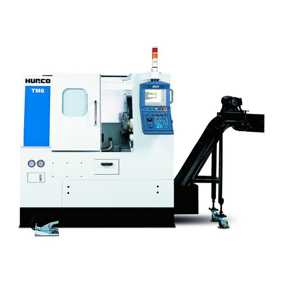
ACHINE AND OFTWARE PTIONS Chip Conveyor The chip conveyor is available as a machine option. The chip conveyor removes material from the machine while the part is being machined. UltiDraw DXF Option The UltiDraw Data Exchange Format (DXF) File option allows you to rapidly create Conversational part programs from 2D CAD drawings. - Page 34 PRE 704-0214-101, B 4 - 2 Machine and Software Options LatheGetting Started Manual...
- Page 35 1 - 11 NDEX Hurco training 3 - 2 Installation Capacities Hurco Field Service Engineer coolant tank 1 - 12 machine 3 - 2 forklift 2 - 3 transformer 3 - 2 Coolant machine 3 - 2 flood tank...
- Page 36 Machine Lubrication 1 - 13 Machine Lubrication, Lubrication 1 - 13 UltiDraw DXF Option 4 - 1 Ultimax removing console from shipping pallet 2 - 3 Operating Unloading machine machine dimensions 1 - 5 from pallet 2 - 4 temperature 1 - 11 Unpacking machine equipment 2 - 3...
Need help?
Do you have a question about the TM6 and is the answer not in the manual?
Questions and answers