Table of Contents
Advertisement
Quick Links
Spaside Remote Control
for Aqua Logic and Pro Logic
Owner's Manual
.....
620 Division Street, Elizabeth NJ 07207
USE ONLY HAYWARD GENUINE REPLACEMENT PARTS
Contents
Compatibility.........................1
Installation............................1
Operation..............................7
Troubleshooting....................9
Warranty..............................14
Hayward Pool Products
Phone: (908) 355-7995
www.hayward.com
092081C RevE
Advertisement
Table of Contents

Related Manuals for Hayward AQL-SS-6B


Summary of Contents for Hayward AQL-SS-6B
- Page 1 092081C RevE Spaside Remote Control for Aqua Logic and Pro Logic Owner’s Manual ..Contents Compatibility......1 Installation......1 Operation......7 Troubleshooting....9 Warranty......14 AQL-SS-6B AQL-SS-D Hayward Pool Products 620 Division Street, Elizabeth NJ 07207 Phone: (908) 355-7995 www.hayward.com USE ONLY HAYWARD GENUINE REPLACEMENT PARTS...
- Page 2 Aqua Logic manual to determine software version). The AQL-SS-6B is also configurable when used with the Aqua Logic P-4 running software version 2.40 or later. The AQL-SS-6B is compat- ible with PS and P4 models prior to version 2.40, but is not configurable (the buttons are fixed to operate specific functions).
- Page 3 O-Ring 4. When the spa construction is completed, cut back the PVC conduit receptacle flush with the spa wall or surface of the deck. Run the cable from the AQL-SS-6B/D through the conduit to the Pro Logic or Aqua Logic.
- Page 4 O-ring is inserted into the PVC pipe. Refer to the diagram below and follow the following steps: Find the desired location for the installation of the AQL-SS-6B/D and cut out the hole using one of the included templates (page 10). The remote should be mounted in a location above the high water mark.
- Page 5 Cutout templates are provided on page 10. Wiring The AQL-SS-6B/D comes with 150 ft. of 5-conductor 24 AWG outdoor rated cable. In most ap- plications, the cable will need to be shortened. Follow the wiring instructions below: Turn off AC power to the Pro Logic or Aqua Logic Run the cable through the conduit from the remote mounting location to the Pro Logic/Aqua Logic.
- Page 6 Up to 3 wired remote controls of any type can be connected to the Pro Logic or Aqua Logic. The AQL-SS-6B and AQL-SS-D are wired to the Pro Logic/Aqua Logic in one of 3 ways, depending on how many wired spa side controls will be used. Refer to diagram on page 4. For a single remote control, use “Configuration A”...
- Page 7 Select which of the available remote controls (A, B or C) is to be configured. 6B A, Button 1 This menu allows the user to map each button of the AQL-SS-6B to one of the standard Pro Logic/Aqua Logic functions. The default selections are: Button 1 - Pool/Spa, Button 2 - Filter, Button 3 - Lights, Button 4 - Heater1, Button 5 - Aux1 and Button 6 - Aux2.
- Page 8 LED lights next to the labels will indicate the status of the function. The operation of functions that are controlled by the AQL-SS-6B will vary. On/Off functions like “Lights” and “Aux’s” operate in the same manner. Other functions like “Heater” and “Pool/Spa”...
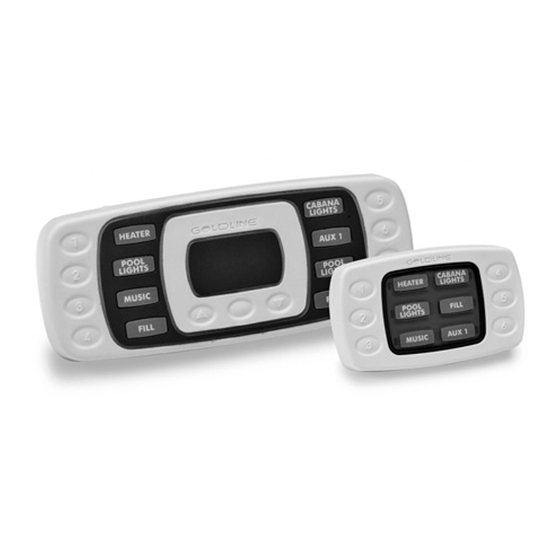
- Page 9 The AQL-SS-D can only be used with Pro Logic PS models and Aqua Logic PS models running software version 2.40 or greater. It is similar to the AQL-SS-6B except that it has 2 more function buttons as well as 3 buttons underneath the LED display. The 8 functions operate in the same manner as the AQL-SS-6B.
-
Page 10: Troubleshooting
AQL-SS-6B/D cable is correctly wired to the terminal block according to page 4. If OK, cycle the Pro Logic/Aqua Logic’s power off and on. If using the AQL-SS-6B and Aqua Logic software version 2.40 or greater, make sure that the buttons are properly configured in the configuration menu (page 5 - 6). - Page 11 USE ONLY HAYWARD GENUINE REPLACEMENT PARTS...
- Page 12 USE ONLY HAYWARD GENUINE REPLACEMENT PARTS...
- Page 13 USE ONLY HAYWARD GENUINE REPLACEMENT PARTS...
- Page 14 USE ONLY HAYWARD GENUINE REPLACEMENT PARTS...
- Page 15 (3) years. Hayward also warrants its Aqua Trol chlorination products to be free of defects in materials and workmanship, under normal use and service for a period of one (1) year. These warran- ties are applicable from the initial date of purchase on private residential swimming pools in the US and Canada.
- Page 16 Hayward is a registered trademark of Hayward Industries, Inc. © 2016 Hayward Industries, Inc. All other trademarks not owned by Hayward are the property of their respective owners. Hayward is not in any way affiliated with or endorsed by those third parties.
Need help?
Do you have a question about the AQL-SS-6B and is the answer not in the manual?
Questions and answers