Bendix/King Skymap IIIC Operating Manual
Hide thumbs
Also See for Skymap IIIC:
- Pilot's manual (67 pages) ,
- Manual (6 pages) ,
- Quick reference (6 pages)
Table of Contents
Advertisement
Skymap IIIC & Tracker IIIC
Pilot Guide & Operating Manual
Manual Revision: SM2105-07 SIIIC Pilots Guide
Unit Software Version 1.11+ (System Model Packages SM4000 & TR4000)
Aeronautical Database: - Supplied courtesy of Jeppesen®
2000 Skyforce Avionics Ltd,
(A subsidiary of Honeywell Inc)
5 The Old Granary,
Boxgrove,
Chichester,
West Sussex PO18 0ES,
UK
Information in this document is subject to change without notice. Honeywell reserves the right
to change or improve its products and to make changes in the content without notification.
i
Advertisement
Table of Contents

Related Manuals for Bendix/King Skymap IIIC


Summary of Contents for Bendix/King Skymap IIIC
- Page 1 Skymap IIIC & Tracker IIIC Pilot Guide & Operating Manual Manual Revision: SM2105-07 SIIIC Pilots Guide Unit Software Version 1.11+ (System Model Packages SM4000 & TR4000) Aeronautical Database: - Supplied courtesy of Jeppesen® 2000 Skyforce Avionics Ltd,...
- Page 2 EMORY 5 TITLE AND HELP SCREENS ......................5-1 ......................5-1 EST AND NITIALISATION .......................... 5-2 CREEN ..........................5-3 CREEN 6 GPS STATUS SCREENS (SKYMAP IIIC ONLY) ................6-1 ........................ 6-3 DJUSTING IME AND ......................6-4 ETTING OCAL FFSET ......................6-4...
- Page 3 ..........................8-1 AYPOINTS ........................ 8-3 IEWING AYPOINTS ..................... 8-4 ANUAL AYPOINT DITING ....................8-5 RAPHICAL AYPOINT DITING ........................8-6 DITING IRPORTS ........................... 8-6 LIGHT LANS ..................8-7 ANUAL LIGHT UILDING AND DITING DIRECT TO......8-8 ANUALLY NSERTING A AYPOINT INTO A LIGHT LAN AND ANUAL...
- Page 4 APPENDIX 04: DIFFERENTIAL FUNCTIONS (SKYMAP IIIC ONLY)...........1 DGPS? ...........................1 DGPS W ?........................1 DGPS ............................1 ..........................2 ONNECTION APPENDIX 05: SKYMAP IIIC SERIAL DATA OUTPUT SENTENCES..........1 NMEA 0183 D ........................1 ORMAT RS-232C AR-NAV D ......................3 ORMAT APPENDIX 06: SERVICE AND WARRANTY ..................1...
- Page 5 Screen 35: Data Input/Output Setup and Test Screen .............. 14-14 Screen 35B: GPS Source Change Warning Screen ..............14-14 Screen 37: Aviation Interface Output Test Screen (Skymap IIIC only)........14-15 Screen 38: Basic Map Mode Screen ....................9-1 Screen 39: Map Mode with Joystick Active Screen ..............9-2 Screen 40: Map Mode Airfield Info Screen..................
- Page 6 Screen 48: NAV Information and TP IMMINENT Flags Showing - Enroute Screen....11-3 Screen 49: NAV Information and TP IMMINENT Flags Showing - Final Screen....... 11-4 Screen 50: Representation of Screen 47 Showing DEMO MODE Flag ........12-2 Screen 51: RAM Lost Warning Screen ................Appendix 01 Screen 52: Memory Battery Warning Screen..............
-
Page 7: Introduction
GPS equipment. Use this equipment at your own risk. Your new Bendix/King equipment is a precision navigation aid but like any navaid it can be misused or misinterpreted and so become unsafe. You are strongly advised to read and fully understand this Manual before using it. -
Page 8: Definitions, Acronyms And Abbreviations
DEFINITIONS, ACRONYMS AND ABBREVIATIONS Definitions alphabetic: any of the following characters (b/ is a space): b/ABCDEFGHIJKLMNOPQRSTUVWXYZ alphanumeric: any of the following characters (b/ is a space): b/ABCDEFGHIJKLMNOPQRSTUVWXYZ0123456789 baud: bits per sec barometric altitude: pressure altitude corrected for barometric altimeter setting bearing to user waypoint: bearing from the present position to the active user waypoint measured clockwise relative to true or magnetic north (true is implied unless magnetic is specified) cross track error: distance from the present position to the nearest point on the desired course, and... - Page 9 greater than 7000 feet clears all terrain by 2000 feet. A sector is an area bounded by a 1 latitude/longitude grid. RAIM: Receiver Autonomous Integrity Monitoring - A technique whereby a GPS receiver determines the integrity of the GPS navigation signals by a consistency check among redundant pseudo range measurements.
-
Page 10: Acronyms And Abbreviations
Acronyms and Abbreviations. alternating current ACT: active (user waypoint or flight plan) ADF: automatic direction finder ANSI: American National Standards Institute APT: airport ARTCC: air route traffic control centre ASCII: American standard code for information interchange ATC: air traffic control ATF: aerodrome traffic frequency ATIS:... - Page 11 pounds LED: light emitting diode LON: longitude LONG: longitude LRU: line replaceable unit meters milliamperes MATZ: Military air traffic zone MAHP: missed approach holding point MAP: missed approach point millibars mandatory frequency MHz: megahertz statute miles min: minutes MOA: military operation area MSA: minimum safe altitude msec:...
-
Page 12: A Quick Look At Your Unit
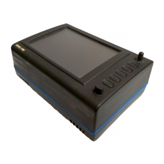
Skymap IIIC Front View Skymap IIIC Rear View KEY TO DRAWINGS Joystick Function Keys ON / OFF / Brightness control Full Colour TFT Liquid Crystal Display. Leg Strap Slot. Accessory Mounting Point. Rear Cover Fasteners. Antenna Socket (Skymap IIIC only) Power/Data Connector. -
Page 13: Standard Accessories
Memory Card. Cooling Air Intake (do not block). Cooling Air Exhaust (do not block). Rear Case Earth Tab (do not bend). Standard Accessories SM2100 Portable Antenna with Cable and Suction Cup (Skymap IIIC only) SM2104 Carrying Case SM2200 Leg Strap SM2207... -
Page 15: General Information
Screen Orientation The Skymap IIIC and Tracker IIIC software can be run in one of four display modes and so allows you to mount the unit either horizontally (either landscape standard or inverse) or vertically (either portrait standard or inverse). This enables the user to configure the unit for either left or right handed operation or place the Keys along the left, right, top or bottom edges of the case. -
Page 16: Data Input
Allows the PIN security function to be Setup. INST & DIAGS Allows installation and diagnostics for data input/output and GPS receiver (Skymap IIIC only) to be performed. Flight logs can be viewed and various sections of memory can be cleared from here. - Page 17 The RAM is maintained by battery power from an internal Lithium cell, which should be replaced by your Bendix/King dealer every three years to prevent loss of user-defined data. The NVM (Non Volatile Memory) is also built into the unit. It stores initialisation data, serial number, PIN number and performance log details.
-
Page 19: Power And Antenna Considerations
Data Input Section of this Manual for more details. If your unit is a Skymap IIIC, the yellow core (data in) can also be connected to the data output line of another GPS, if required and the Skymap IIIC can be switched to Tracker mode and used as a repeater for that GPS. - Page 20 The data presented across the data output pins is controlled by the settings on Screen 35, Data I Input/Output Setup and Test Screen. If you want to connect an external audio annunciator to your unit, do so in accordance with the following drawing and activate it’s operation on Screen 23, NAV Mode Customisation Screen by setting EXTERNAL ALARM to ON.
- Page 21 If the position in which you wish to locate your Skymap IIIC is shielded from the sky and the standard antenna cable is not long enough for an acceptable installation bearing the above guidelines in mind, you may choose one of several options for remote antenna sitting.
-
Page 23: Quick Reference Guide
Sections in this Manual. The information contained within this Section is equally applicable to the Tracker IIIC as it is to the Skymap IIIC. Where the Tracker IIIC operation differs, the differences are explained in italic text after each paragraph. -
Page 24: Mode,
Software Structure Since the software is tree structured, an analogy can be drawn between the trunk of a tree and MAIN MENU. This can be accessed after powering on the unit by pressing the HELP key. MAIN MENU has 5 main software branches, which are as follows: •... - Page 25 Database Selection Both the internal (i.e.: Jeppesen and towns) waypoints and user defined waypoints are stored in your unit in a series of databases. During the normal use of your unit you will need to select items from these databases, whether it is to find out airport frequency information, or select a DIRECT TO point or when creating a flight plan.
- Page 26 If you have a ground speed your Bendix/King unit will calculate the time to reach the tip of the on screen pointer. This information is displayed in the PETE (or Pointer ETE) field.
-
Page 27: Waypoint In Flight
Editing/Creating A User Waypoint Manually From MAIN MENU select the FLIGHT PLAN key, followed by USER WPTS. Use the joystick to select the desired user waypoint number or name. Then press the EDIT key and use the joystick to edit the NAME, LAT and LONG fields. The entire user waypoint can be deleted by pressing CLEAR WPT. - Page 28 Editing/Creating A Flight Plan Manually From MAIN MENU select the FLIGHT PLAN key, followed by EDIT FPLN. Use the joystick to select the desired flight plan number and then press SELECT. To insert an item press INSERT ITEM and follow the Database Selection process explained earlier in this Section of the Manual.
- Page 29 Selecting A Flight Plan To Fly From MAIN MENU select the MAP key, followed by NAV MENU and FLIGHT PLAN. Use the joystick to select the desired flight plan number and then press the SELECT key. Ensure that the leg arrow is pointing at the initial leg that is to be flown and press FLY FPLN.
-
Page 30: Earch
Ten Nearest Search The ten nearest airports or beacons can be displayed by either pressing NAV MENU or DIRECT TO in MAP mode, followed by either NEAR APTS (for airports) or NEAR NAVAID (for beacons). The desired information will be presented dynamically as a bearing and distance from your present position. -
Page 31: F Unctions
On the initial page, each of the displayed features can be set by using the joystick. The features are as follows: ORIENTATION: Set either in Track Up or North Up. AIRPORT NAMES: Labels airports in MAP mode either with ICAO code, airport or city names. MAP UNITS: Sets all map units to ether nautical miles, statute miles or kilometres. -
Page 32: Clear Memory
Each of the displayed features can be set by using the joystick. They are as follows: CDI SCALE: Sets the full scale deflection of displayed CDIs to 0.3, 1.0, 2.5 or 5.0nm. CDI DISPLAY: Either turns the CDI display off, or sets it to either a numeric or bar display. CDI ALARM: Switches the CDI alarm on or off. -
Page 33: Title And Help Screens
Key 3 calls Screen 20, which is the Demo Mode Setup Screen. (If, since being switched on, the unit has received valid fix information from the internal GPS receiver (Skymap IIIC) or from an external device (Tracker IIIC), Key 3 DEMO MODE will for safety reasons be blanked and disabled.) This is the only Screen on which Demo Mode can be activated. -
Page 34: Main Menu Screen
Change Warning Screen, will be displayed (Refer to Appendix 01). 6. If the unit is a Skymap IIIC the GPS receiver circuitry will be tested and if any problems are found, a NO REPLY message will be indicated in the STATUS field of Screen 3, GPS Status Screen. -
Page 35: Screen 62: Notepad Screen
Using the 'Flight Manager' software you can prepare and store a library of Note Pad files and load the relevant one into your Bendix/King unit to suit your day's flying. Screen 62 also gives access to the E6-B Calculator Screens. -
Page 37: Gps Status Screens (Skymap Iiic Only)
DIFFERENTIAL This word will be displayed in conjunction with 2D FIX or 3D FIX and means that the Skymap IIIC has a fix and is also receiving differential correction signals from an external source. (Refer to Appendix 04 for further details concerning differential operation.) ACQUIRING means the unit is currently searching for satellites or is loading information from one or more satellites. - Page 38 Other information that is displayed on this Screen includes: DOP (Dilution of Precision), This is a number between 00.0 and 99.0 that represents the dilution of quality of the calculated fix due to satellite geometry. 00.0 is best, 99.9 is worst. If this figure is greater than 5.0, performance of the system is likely to be degraded because some of the visible satellites appear too close to each other.
-
Page 39: Date
When using the Skymap IIIC for the first time (or after it has been relocated by more than 100 miles since it was last used) setting up the present position (to within 50 miles or so) and ensuring that UTC and Date are correct (to within a few minutes) will considerably speed up the TTFF (time to first fix). -
Page 40: Time Offset
Setting Local Time Offset Screen 5: Local Time Offset Screen Pressing GPS STATUS in Main Menu, followed by LOCAL OFFSET, accesses this Screen. When this Screen initially appears a cursor will be active in the data entry field. The hour’s value can be adjusted between the limits of +12 and -12 by using the joystick. -
Page 41: Screen 10A: View Map Screen
Screen 10A: View Map Screen When Screen 10A is displayed you can zoom in or out using Keys 3 or 4. By using the joystick you can ‘bump’ the borders of the map window to view anywhere in the world. The POS: box at the bottom of the screen displays the latitude and longitude of the pointer. - Page 43 Tracker IIIC has no internal GPS receiver and so requires a data input from a separate GPS or LORAN unit in order to function in Map Mode. If required, the Skymap IIIC can also be run in Tracker mode using an external GPS or LORAN unit. (Refer to Data In/Out in the Setup Screens Section of the Manual).
-
Page 44: Screen 35(T): Data Input/Output Setup And Test Screen
Screen 35(T): Data Input/Output Setup and Test Screen If your GPS or LORAN is correctly connected, switched on and outputting data, your Tracker IIIC will automatically start to read and decode the incoming data. There is no need to set an input type on the Tracker IIIC as this is done automatically. -
Page 45: User Waypoints
A user waypoint is a specific location anywhere in the world, defined by an icon, a name of up to nine letters or numbers and by a latitude and longitude. In your new Bendix/King equipment there are three types of user-defined user waypoints, each with a specific function. -
Page 46: Screen 7: Flight Planning Mode Cover Screen
be included in the ten nearest airports search on Screen 43, Ten Nearest Airports Screen, and will receive equal priority with other database airports for position reporting purposes. On Screen 39, MAP Mode with Joystick Active Screen, if the pointer is placed over a user-defined airport and the MORE INFO Key is pressed, Screen 40, Map Mode Airport Information Screen, will be displayed with the data you have entered being displayed. -
Page 47: W Aypoints
Viewing User Waypoints Screen 8: User Waypoint Viewer Screen Pressing FLIGHT PLAN in Main Menu, followed by USER WPTS, accesses this Screen. When this Screen appears a cursor will be seen positioned over the WPT field. Use the joystick to increment or decrement the user waypoint number. -
Page 48: Screen 9: Manual User Waypoint Edit Screen
Manual User Waypoint Editing Screen 9: Manual User Waypoint Edit Screen Pressing FLIGHT PLAN in Main Menu, followed by USER WPTS and EDIT, accesses this Screen. On entry to this Screen a cursor appears over the word NAME. The cursor can be moved up and down between NAME, LAT, LONG and ICON using the joystick. -
Page 49: Screen 10: View And Edit User Waypoints On The Map Screen
Graphical User Waypoint Editing Screen 10: View and Edit User Waypoints on the Map Screen When this Screen first appears, after pressing VIEW MAP on Screen 8, User Waypoint Viewer Screen, the selected user waypoint will be centrally positioned. The joystick can be used to move the pointer. -
Page 50: Flight Plans
Editing User Airports Screen 8A: User Airport Edit Screen Whenever you select a user waypoint number between 101 and 125 in Screen 8, User Waypoint Viewer Screen, Screen 8A, User Airport Edit Screen will be displayed. This is similar to Screen 8 but contains data entry fields where you can enter and store additional information about the airport's main runway and frequencies. -
Page 51: E Diting
Key 1, PREV PAGE, returns you to the Flight Planning Mode Cover Screen. Key 5, VIEW MAP, calls Screen 19, enabling you to edit the selected flight plan graphically on the map. Key 4, TRIP/FUEL gives access to the trip and fuel planning function. For more information on this function please refer to the Trip/Fuel Planning information in the E6B Calculator Section of this Manual. -
Page 52: Flight Plan And Manual Direct To
In the example shown in the illustration for Screen 12, moving the joystick down would move the cursor down over 01 (or Waypoint 1) but would leave the “LEG” arrow positioned as it was. The distance shown next to the word LEG also would remain unchanged, showing the leg distance from the flight plan start point to Waypoint 01 (01). -
Page 53: Screen 15: Direct To Destination Input Screen
As stated above, Key 5, TEMP WPT, only appears if this Screen has been entered after performing a DIRECT TO in Screen 38, MAP Mode. If you press Key 5, this will take you to Screen 15 (see below), which allows you to enter a DIRECT TO point. If Key 1, PREV PAGE, is pressed to discontinue the selection process the unit will return to whichever the previous Screen was, Screen 12, Flight Plan Program/Edit Screen, or Screen 38, MAP Mode. - Page 54 If AIRPORTS, VORS, NDBS, INTS or AIRWAYS was selected on Screen 13, the first item in the data entry box on screen 16 is AREA:. This is an area filter, which can be set to a specific ICAO country or area code.
-
Page 55: Flight Plan
Graphical Viewing and Editing of Flight Plans Screen 19: View and Edit Flight Plans On Map Screen This Screen is accessed by pressing FLIGHT PLAN in Main Menu, followed by EDIT FPLN and Key 5, View Map, on Screen 11, Flight Plan Selection Screen. Screen 19 is displayed showing the starting point of the selected flight plan centred in the middle of the display. - Page 56 If, for example you wanted to add DEAL into the existing flight plan going from MANSTON to DOVER VOR shown in the illustration above, you would first position the pointer over the track line between Manston and Dover VOR, thereby highlighting it and then press Key 2, GRAB LINE. This will pick up the line.
-
Page 57: Map Mode Screens
This Screen can be accessed by pressing MAP mode in Main Menu. When you enter this Screen, if the Skymap IIIC's internal GPS receiver has been able to establish a fix or if the external GPS you are using to feed your Tracker IIIC is sending valid data, a Screen similar to the above will be displayed. -
Page 58: Direct To
All airport names are shown preceded by an asterisk character (*) in order to distinguish them from towns or cities with similar names, which may have significantly different locations. If your position is found to be within five miles of a VOR beacon and more than five miles from an airport, then your position will be shown with respect to the VOR beacon, even if there is a user waypoint, NDB or town nearer. - Page 59 In addition to finding it useful for measuring distances, bearings and ETE's, you can utilise this Screen for other tasks. If you place the pointer over any data icon and then press Key 4, MORE INFO, Screen 40 (Airport), Screen 40A (Beacon) or Screen 40C (all other data icons) as illustrated below will appear. These Screens contain additional data and information on the selected item.
-
Page 60: Beacon Information
Beacon Information Screen 40A: Map Mode Beacon Information Screen As explained above, you can access this Screen from Screen 39 by placing the joystick pointer over a VOR or NDB icon and pressing Key 4, MORE INFO. Full details of the Beacon are listed, type, frequency and ident. -
Page 61: General Icon Information
General Icon Information Screen 40C: Map Mode General Information Screen As explained above, you can access this Screen from Screen 39 by placing the joystick pointer over any data icon that is not an airport, VOR or NDB and pressing Key 4, MORE INFO. All available information concerning the chosen data item is then listed. -
Page 62: Airspace Interrogation
Airspace Interrogation In order to interrogate a piece of airspace in MAP Mode, move the joystick operated pointer and point at one of the airspace boundaries. After you have released the joystick, the software will search the airspace database and after a short time will re-draw the piece of airspace to which you have pointed in a bolder line. -
Page 63: Nav Menu Screens
10 NAV MENU SCREENS Screen 41: NAV Menu Cover Screen You can enter this important Screen by pressing Key 4, NAV MENU, while in MAP Mode (on Screen 38 or 47). It is a versatile Screen with several useful functions. If you move the joystick up or down when in this Screen, the screen layout presented when in Map Mode with NAV Information (or NAV Mode i.e. -
Page 64: Screen 42: Flight Plan Selection Screen
The text boxes in the bottom half of the screen gives the following information: NAV Mode selected (one of six options described above) Position in plain English Position in latitude/longitude (or the co-ordinate system selected on the Map Setup Screen) Track and Ground Speed GPS Altitude MSA for the present position... -
Page 65: Airports
Screen 12: Flight Plan Program/Edit Screen In order to select a flight plan to fly, bring up the desired Flight plan Number with the joystick and press Key 2, SELECT, in Screen 42, Flight Plan Selection Screen. This will call Screen 12 from which you can choose to edit the flight plan, reverse the flight plan or activate the flight plan. - Page 66 You can scroll up and down the list by using the joystick. Once the cursor is lying over the name of the airport you require, if you press Key 3, MORE INFO, Screen 44 below will appear, giving you additional information about that airport.
-
Page 67: Beacons
Beacons Screen 45: Ten Nearest Beacons Screen This Screen is accessed by pressing Key 4, NEAR NAVAID, on Screen 41, NAV Menu Cover Screen, and dynamically shows the range and bearing of the ten nearest beacons. When this Screen appears you will find a cursor placed over the first beacon in the list. - Page 68 From here by pressing Key 2 you will get back to MAP mode (Screen 38 or 47). To select another beacon from the Ten Nearest (Screen 45) you press Key 1. If you press Key 3, IDENT, the unit will mimic the Morse code ident for the chosen beacon on the internal beeper (and on the external alarm if you switched this on in Screen 23, NAV Mode Customisation Screen).
-
Page 69: Map Mode With Nav Information
11 MAP MODE WITH NAV INFORMATION Whenever a flight plan is active or you have called for a DIRECT TO, the map will have extra navigation information added to it and will resemble Screen 47 below. Alternatively you may have selected one of the other Navigation Modes detailed in the NAV Menu Screens Section of this Manual. -
Page 70: To Page
On the Skymap IIIC unit only, at the top right of the map is the ETA. This is the Estimated Time of Arrival at the next turning point. Ensure you have set the local time offset correctly to get correct ETA’s. -
Page 71: Aypoint
Direct-To The Direct-To function allows you to perform a short cut whilst flying a flight plan by skipping over intermediate legs and flying directly to a point further along your planned flight plan. Once the selected point is reached, the normal flight plan is automatically resumed. A black cursor bar is hidden behind the Magenta bar which is highlighting the current destination waypoint. - Page 72 When the WPT Alert alarm has been given, a new box will appear at the bottom of the screen showing the new course [NEW CRS XXX] to steer for the next leg of the flight plan. The next leg of the flight plan will also be displayed as a solid white line.
-
Page 73: Topo On / Topo Off Large Text Mode
Alternative Navigation Map Modes You may have selected one of the other Map presentation modes detailed in the NAV Menu Screens Section of this Manual. The same navigation data as described previously is presented on all the alternative screens in different ways. TOPO ON / TOPO OFF Large Text Mode Screen 47A: TOPO ON Large Text NAV Information Screen. -
Page 74: Topo On / Topo Off Cdi (Pseudo Hsi) Mode:
TOPO ON / TOPO OFF CDI (Pseudo HSI) Mode: Screen 47B: CDI (Pseudo HSI) NAV Information Screen This Screen presents numeric navigation information in small text but instead of a map display, shows a pseudo CDI complete with OBS knob. The aircraft icon in the center of the CDI will remain static and the outer ring represents the desired magnetic track between the start waypoint and the destination waypoint (i.e. - Page 75 This has the effect of rotating your desired track ring and hence rotating the desired track line on the map screen using the destination point as a pivot. For example if you were approaching an airport from the south west on an inbound heading of 070° but the runway in use at that airport was 09, it may be desirable to approach the airport on a heading of 090°...
-
Page 77: Demo Mode
This Demo Mode Screen can be accessed by pressing Key 3, DEMO MODE, on Screen 1, Title Screen, provided that, since the time you switched it on, your Skymap IIIC has not received valid satellite information from its internal GPS receiver, or your Tracker IIIC similarly lacks fix data from its external receiver. -
Page 78: Screen 50: Representation Of Screen 47 Showing Demo Mode Flag
Screen 50: Representation of Screen 47 Showing DEMO MODE Flag If Demo Mode is active and you switch to Screen 2, Main Menu Screen, you will see Key 3 is now labelled DEMO OFF and can be used to cancel Demo Mode. 12-2... -
Page 79: E6-B Calculator
13 E6-B CALCULATOR E6-B functions are accessible by pressing Key 3, NOTE PAD, in Main Menu followed by Key 3, E6-B CALC, in the Note Pad Screen. This gives access to Screen 57, E6-B Calculator Screen. This function is not available in Demo Mode. Screen 57: E6-B Calculator Cover Screen Key 1 returns you to Screen 2 Main Menu. - Page 80 1. Enter the altitude reading from your altimeter next to the IALT heading. Default value on entry to Screen is GPS altitude for Skymap IIIC or 2000 for Tracker IIIC. 2. Move the cursor over the entry field next to the heading IAS/CAS and enter your indicated or calibrated airspeed.
-
Page 81: Screen 59: V Nav Setup Screen
BY. On entry to this Screen, the FROM value will default to GPS altitude if your unit is a Skymap IIIC or to 5000 feet if your unit is a Tracker IIIC (or the last set value). The TO value will default to 1500 feet (or the last set value). -
Page 82: Screen 60: Trip / Fuel Flight Plan Select Screen
VNAV can be used for climbing as well as descending. If the FROM altitude is set to a lower value than the TO altitude then everywhere the words DESCENT and DESCEND appear, the word CLIMB will be used instead. Trip/Fuel Planning This feature is entered by pressing Key 4, TRIP/FUEL, on Screen 57, E6-B Calculator Cover Screen, and allows you to call up any flight plan and view the following details about each leg of the flight plan. -
Page 83: C Alculator
On entry to this Screen the present or last known latitude and longitude will show. The present date (Skymap IIIC only) will also show. If your unit is a Tracker IIIC, a default date value will be displayed. You can now alter the latitude, longitude and time with the joystick or alter the latitude and longitude by choosing an item from the database. -
Page 85: Setup Screens
14 SETUP SCREENS Screen 21: Setup Cover Screen Your Bendix/King unit allows you a great deal of flexibility to customise it to suit your own wishes and requirements. It also contains a high level of automatic self-testing and diagnostics. All customisation and diagnostic functions are grouped together in this Setup section. - Page 86 When the cursor is over the heading you wish to alter, move the joystick to the right. This will in turn move the cursor over to the set of options available for that heading. Moving the joystick up and down will then allow you to scroll through these options.
- Page 87 EXT TRACK: If Extended Track is turned on, you will see an extended track line drawn ahead of your present position in the direction of your present track. This can sometimes be useful to see just where the aircraft would end up if the present heading were maintained. Alternatively you can dispense with this map feature simply by selecting EXT TRACK to OFF.
-
Page 88: Screen 22A: Point Features Data Class Setup Screen
Screen 22A: Point Features Data Class Setup Screen Screens 22A, 22B and 22C, the Data Class Setup Screens are accessed by repeatedly pressing Key 5, NEXT. It is impossible to include every item from the database within the graphic map display, especially when zoomed out to the smaller scale maps. -
Page 89: Screen 22C: Airspace Data Class Setup Screen
Screen 22C: Airspace Data Class Setup Screen Please think carefully before altering any of the settings on these screens. You may inadvertently switch off an important data class (such as obstacles), which could compromise your situation awareness. NAV Mode Setup Screen 23: NAV Mode Customisation Screen When you first enter this Screen the current settings are displayed with a cursor over the words CDI SCALE. - Page 90 AUTO NEXT LEG: on / off. TURN ANTICIPATION: on / off FLIGHT PLAN DISPLAY: all legs / active leg. INTERNAL ALARM: on / off. EXTERNAL ALARM: on / off. CDI SCALE: This enables you to choose which of the given distances you want the unit to use as the setting for the full-scale deflection of the Course Deviation Indicator (CDI) in NAV mode.
-
Page 91: Screen 24: Pin Setup Cover Screen
Personal Identification Number (PIN) Setup Screen 24: PIN Setup Cover Screen We have provided the security feature of a Personal Identification Number (PIN) in your Bendix/King unit with the main aim of preventing unauthorised persons from using your navigation equipment. You may use this Screen to set up your own choice of a four-digit personal number. -
Page 92: Screen 26: Pin Change & Power-On Lock Enable Screen
Bendix/King unit. Should you have the misfortune to forget your number, keep trying; there are only 256 permutations! Screen 26: PIN Change & Power-On Lock Enable Screen If you have managed to get the PIN correct then you move straight to Screen 26 as illustrated above. -
Page 93: Screen 28: Installation And Diagnostics Cover Screen
Screen 55 (see Appendix 01). If this happens to you, in order to re-activate the unit, you will have to telephone Honeywell or your Bendix/King dealer, armed with the Serial Number of your unit and the Lock-Out Number, which you can read from the top of Screen 55. The operator at your dealer or at Honeywell will verify these details and check them against the Honeywell database and register of stolen units. -
Page 94: View Logs
Ground Speed exceeds 20 knots and the Stop Time is logged whenever the Ground Speed drops back to less than 3 knots. Key 2, GPS RX LOG, is available only on Skymap IIIC units and gives access to the GPS Receiver Engineering Log Screen 31. -
Page 95: Gps Receiver Information Log
GPS Receiver Information Log Screen 31: GPS Receiver Information Screen (Skymap IIIC only) Most of the information on this Screen is technical engineering information about the internal GPS receiver. The Total Fix Hours figure increases only during the periods when the GPS receiver has a 2D or 3D fix. -
Page 96: Screen 33: Memory Clear Cover Screen
Screen 33: Memory Clear Cover Screen Be careful to handle operations from this Screen correctly, otherwise you could lose valuable and important data from the memory of your unit. If for instance you press Key 2, labelled “CLEAR FPLNs”, you will go straight to a warning Screen that reads “Clear Memory. -
Page 97: Data In/Out
DATA OUTPUT: OFF / RS232 (AR NAV) 9600 BAUD / NMEA 0183 4800 BAUD / AVIONICS INTERFACE. The GPS SOURCE allows you to use your Skymap IIIC as a Tracker IIIC. When you move the cursor to the right of this field the following Warning / confirmation request shall be displayed: Screen 35B: GPS Source Change Warning Screen If you press ABORT the GPS source remains unchanged. -
Page 98: Output Test
If the data is valid and useable, the word YES will appear next to the words DATA VALID, if the data is not valid or useable then the word NO will be displayed. When Skymap IIIC is used with an external GPS source, the data output will be limited to OFF and ECHO INPUT. -
Page 99: Appendix 01: Warning Screens
By pressing Key 1 you can return to whichever Screen was showing before the low voltage condition was detected. If this screen is displayed, you should have your memory battery replaced by your Bendix/King dealer at the earliest possible opportunity. Appendix 01 - 1... -
Page 100: Pin Lock Warning
PIN Lock Warning Screen 54: Power On Security PIN Entry Screen If the Auto Power-On Lock function has been activated on Screen 26, this Screen will be called during initialisation. You must then input the correct PIN before you are allowed to move back to Screen 1 with full access to all functions. -
Page 101: New Data Card Warning
If you get locked out of the unit, in order to re-activate the unit, you will need to telephone Honeywell or your local Bendix/King dealer and provide them with your Serial Number and the Lockout Number. Your details will be verified and checked against the Honeywell database and register of stolen units. - Page 102 CHANGING DATABASE REFERENCE PLEASE CONFIRM Pressing Key 1 will change the database reference displayed on Screen 12, Flight Plan Program/Edit Screen, to OW indicating that this item is now an Old User Waypoint and is no longer accessible from any database. This check is carried out for every point in every flight plan and whenever discrepancies are found, Screen 56 will appear on each occasion.
-
Page 103: Data Areas
Honeywell produce a series of memory cards based on the ICAO/ARINC geographic areas for Skymap IIIC and Tracker IIIC that cover the entire world. Each card for each area contains the operating software, the appropriate Jeppesen aeronautical data and cartographic data to a high resolution. -
Page 104: Flight Plan Building
5001 feet MSL or higher. Grid MORAs are defined for all areas. In Skymap IIIC the Grid MORA information is used in two ways to derive Minimum Safe Altitudes (MSA), firstly during flight plan building and secondly during actual flight. - Page 105 BURUNDI, REPUBLIC OF BURUNDI CAMEROON, UNITED REPUBLIC OF CAMEROON CANARY ISLANDS (SPAIN) CANARY IS CAPE VERDE, REPUBLIC OF CAPE VERDE CENTRAL AFRICAN REPUBLIC CENTRAL AFRICAN REP CHAD, REPUBLIC OF CHAD CHAGOS ARCHIPELAGO CHAGOS ARCHIPELAGO COMOROS, ISLAMIC FED REP OF COMOROS CONGO, REPUBLIC OF THE CONGO DAKAR FIR/UIR...
- Page 106 TUNISIA, REPUBLIC OF TUNISIA UGANDA, REPUBLIC OF UGANDA ZAIRE, REPUBLIC OF ZAIRE ZAMBIA, REPUBLIC OF ZAMBIA ZIMBABWE, REPUBLIC OF ZIMBABWE Official Country Name ICAO Jeppesen Standard Name State Area ALASKA ALASKA ALBERTA ALBERTA BRITISH COLUMBIA BRITISH COLUMBIA CANADA CANADA MANITOBA MANITOBA NEW BRUNSWICK NEW BRUNSWICK...
- Page 107 RUSSIAN FEDERATION RUSSIA RUSSIAN FEDERATION RUSSIA SLOVAK REPUBLIC SLOVAKIA TAJIKISTAN, REPUBLIC OF TAJIKISTAN TURKMENISTAN TURKMENISTAN UKRAINE UKRAINE UZBEKISTAN, REPUBLIC OF UZBEKISTAN Official Country Name ICAO Jeppesen Standard Name State Area ALBANIA, REPUBLIC OF ALBANIA AUSTRIA, REPUBLIC OF AUSTRIA AZORES (PORTUGAL) AZORES BELGIUM BELGIUM...
- Page 108 MARTINIQUE MARTINIQUE MEXICO (UNITED MEXICAN STATES) MEXICO MONTSERRAT MONTSERRAT I NETHERLANDS ANTILLES NETH ANTILLES NICARAGUA, REPUBLIC OF NICARAGUA PANAMA, REPUBLIC OF PANAMA PUERTO RICO PUERTO RICO SAINT KITTS AND NEVIS NEVIS I SAINT VINCENT & THE GRENADINES ST VINCENT SAINT LUCIA ST LUCIA SAINT KITTS AND NEVIS ST KITTS...
- Page 109 KOREA, REPUBLIC OF KOREA LAO, PEOPLES DEM REP OF LAOS MACAU MACAU MARIANA ISLANDS MARIANA IS MARSHALL ISLANDS MARSHALL IS MICRONESIA, FED STATES OF MICRONESIA MIDWAY ISLANDS MIDWAY I MYANMAR, UNION OF MYANMAR NORTHERN MARIANA ISLANDS NORTHERN MARIANA IS OAKLAND OCEANIC CONTROL AREA OAKLAND OCTA PALAU, REPUBLIC OF PALAU...
- Page 110 TUAMOTU ISLANDS TUAMOTU IS TUVALU TUVALU VANUATU, REPUBLIC OF VANUATU WALLIS AND FUTUNA ISLANDS FUTUNA IS WALLIS AND FUTUNA ISLANDS WALLIS IS Official Country Name ICAO Jeppesen Standard Name State Area ALABAMA ALABAMA ARIZONA ARIZONA ARKANSAS ARKANSAS BAHAMAS, COMMONWEALTH OF THE MY BAHAMAS BERMUDA ISLANDS BERMUDA...
- Page 111 WISCONSIN WISCONSIN WYOMING WYOMING Appendix 02 - 9...
-
Page 113: What Is Gps
APPENDIX 03: How Does GPS Work? What Is GPS? Many of the radio-navigation aids used in aviation were originally developed for military use but have now been made freely available to civil users. The Global Positioning System (GPS) has a similar history. - Page 114 2) Making use of an extra satellite. In order to obtain a positional fix in three dimensional space, it is necessary to know the exact distance to each of three satellites. The exact distance is however not known because of the presence of an offset or error in the receiver's clock with respect to universal time.
- Page 115 Each satellite has three separate clocks on board (one in use and two standby) and in the event of the total failure of a satellite, one of the spares already in orbit can be manoeuvred into position within a few hours. The only time the DoD can predict there may be a substantial break in coverage for civilian users, is at a time of National Emergency, when the whole system may be reverted to P code (military) operation only, for strategic reasons.
-
Page 117: What Is Dgps
APPENDIX 04: Differential Functions (Skymap IIIC only) Your Bendix/King unit has been designed to enable it to make use of Differential GPS (DGPS). What Is DGPS? GPS on its own is, as we have seen in Appendix 03, an extremely accurate system for all general navigation purposes. -
Page 118: Odes
To connect the Skymap IIIC to a differential receiver unit, common up the 0v or ground lines (pin 5 of the Skymap IIIC connector) and connect the data output line from the differential receiver to pin 1 of the Skymap IIIC connector. - Page 119 APPENDIX 05: Skymap IIIC Serial Data Output Sentences. Skymap IIIC can output standard aviation RS232 data at 9600 baud or NMEA 0183 format RMC, GGA and RMB sentences at 4800 baud. The data output type is Setup on Screen 35 Data input/output Setup and Test Screen.
- Page 120 NMEA – RMB Sentence. $GPRMB,<1>,<2>,<3>,<4>,<5>,<6>,<7>,<8>,<9>,<10>,<11>,<12>,<13>*hhCRLF 1. Position valid (A = valid, V = invalid). 2. XX.XX Cross track error in nautical miles. 3. X Direction to steer (L = left, R = right). 4. XXXX Four character start waypoint identifier. (first four characters of name). 5.
- Page 121 RS-232C AR-NAV Data Format 9600 baud 8 data bits, 1 stop bit, no parity. Type 1 sentence only sent every two seconds. Each line of data is followed by a carriage return (CR) and a line feed (LF) character except the STX and ETX lines. Header Data Description.
- Page 123 Due to the Company's policy of continual development and routine database updates, new Memory Cards will become available every 28 days. As a registered owner of a Tracker IIIC or Skymap IIIC, you will be offered a 1/3/6/12 monthly Memory Card subscription. Keeping your database current is your own responsibility and is extremely important from a safety viewpoint.
Need help?
Do you have a question about the Skymap IIIC and is the answer not in the manual?
Questions and answers