Table of Contents
Advertisement
Advertisement
Table of Contents

Subscribe to Our Youtube Channel
Related Manuals for REXON SM2509R


Summary of Contents for REXON SM2509R
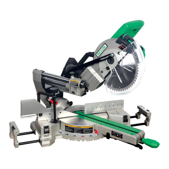
- Page 1 ® 10 IN. (255 MM) SILDE COMPOUND MITER SAW SM2509R INSTRUCTION MANUAL...
- Page 2 CONTENTS P 1 - 16 The original instruction manual is in English.
-
Page 3: Carton Contents
CARTON CONTENTS UNPACKING 1. Carefully remove the miter saw from the carton. 2. Separate and layout all of the parts. Carefully check them according to the diagram below. IMPORTANT: Always use the designated carrying handle and hand-hold on the side of the saw base for transportation. -
Page 4: General Safety Rules
General Safety Rules for the connection of dust extraction and collecting equipment, ensure these are WARNING ! When using electric tools connected and properly used. basic safety precautions should always 11. DO NOT ABUSE THE CABLE. Never be followed to reduce the risk of fire, pull the cable to disconnect it from the electric shock and personal injury. -
Page 5: Miter Saws
Damaged, warped or deformed blades conditions that may affect its operation. A guard or other part that is damaged should not be used. should be properly repaired or replaced 3. Do not use the saw without guards in by an authorised service centre unless position, in good working order and otherwise indicated in this instruction properly maintained. - Page 6 11. The laser fitted onto this mitre saw is of electrical appliances as unsorted municipal waste, use separate collection only designed for this saw. The fitting of facilities. Contact your local government any external, additional or different type for information regarding the collection of laser is not permitted.
- Page 7 To lock the cutting head: When transporting Specification or storing the miter saw, the cutting head should always be locked in the down Motor ....1800 W, 220 V~ 50/60 Hz, position. Double Insulation 1. Press the cutting head down to its No load speed ......
- Page 8 REMOVING AND INSTALLING THE NOTE: ● The dust bag assembly should be TABLE INSERT (FIG. 9) angled toward the right side of the saw WARNING! To avoid injury: for best results. This will also avoid any Always unplug the saw to avoid ●...
- Page 9 45° Bevel Stop Adjustment (Fig. 12, 13) Setting the tool 1. Loosen the bevel locking handle (4), fully extend the sliding fence completely NOTE: This tool is accurately adjusted to the left, and tilt the cutting arm before shipping from the factory. Check completely to the left.
- Page 10 Adjusting Miter Angles: 3. Recheck the blade depth by moving 1. Lift up on the quick-cam locking lever (1) the cutting head front to back through to unlock the table. the full motion of a typical cut along the 2. Move the turntable while lifting up on control arm.
- Page 11 NOTE: With the locking lever in the ● NOTE: All the adjustments for the down position, there must be sufficient operation of this machine have space between the lock nut (3) and the been completed at the factory. Due stop plate (5) to allow the mechanism to to normal wear and use, some unlock.
- Page 12 3. Carefully lower the saw head down to After performing the above adjustments, align the saw blade with the pattern visually check that both the front and top line. Position the saw blade to the left, laser lines are parallel with pattern line. center or right side of the “pattern line”...
- Page 13 Operating the tool Connecting to the Power Supply Check that the power supply and outlet WARNING! Never connect the plug to the used is in accordance with your miter power source outlet until all installations saw. Have a look at the rating plate of the and adjustments are completed and you motor or the rating on the miter saw.
- Page 14 SLIDING FENCE (FIG. 28) Removing 1. Unlock the fence cam locking lever (1) WARNING! The sliding fence must be by pushing it out toward the rear of the extended when making any bevel cut. machine. Failure to extend the sliding fence will 2.
- Page 15 3. Release the positive stop locking WARNING! To avoid injury from lever (2). materials being thrown, always unplug 4. Press down on the quick-cam locking the saw to avoid accidental starting, lever (1) until it locks the miter table in and remove small pieces of material place.
- Page 16 BEVEL CUT (FIG. 34, 35) 33.9° BEVEL DETENT PIN FOR CROWN MOLDINGS (FIG. 36) WARNING! 1. Push the bevel detent pin (1) in toward The sliding fence must be extended ● the rear of the machine. to the left when making bevel cuts. 2.
- Page 17 CROWN MOLDING CUT (FIG. 39) SLIDE CUT (FIG. 40) 1. Crown molding can only be cut flat on WARNING! To avoid injury: the table for this miter saw. Never pull the cutting head assembly ● 2. This miter saw has special miter stops and spinning blade toward you of 31.6°...
- Page 18 Installing the Blade (Fig. 41, 42, 43, 44) Changing Blades Unplug the miter saw before changing/ installing the blade. WARNING! Do not use a blade larger 1. Install a 255 mm blade with a 25.4 mm than 255 mm in diameter. To avoid injury arbor hole with a 15.95 mm reducer from an accidental start, make sure making sure the rotation arrow on the...
- Page 19 Maintenance WARNING! For your own safety, turn the switch off and remove the plug from the power source outlet before maintaining or lubricating your miter saw. GENERAL MAINTENANCE Occasionally use a cloth to wipe off chips and dust from the machine. And oil the rotary parts once a month to extend the tool life.
- Page 20 Fig. 1 Fig. 2 Fig. 5 Fig. 3 Fig. 6 Fig. 4 Fig. 7...
- Page 21 Fig. 8 Fig. 12 Fig. 9 Fig. 13 Fig. 10 Fig. 14 Fig. 11 Fig. 15...
- Page 22 Laser Laser Aperture Warning Label Label Fig. 16 Fig. 20 TOP VIEW Laser line Cutting Blade line Workpiece Laser line Cutting line Fig. 21 Fig. 17 Fig. 22 Fig. 18 Counterclockwise Clockwise Pattern line Laser line Fig. 23 Fig. 19...
- Page 23 Counterclockwise Clockwise Laser line Pattern line Fig. 24 Fig. 27 Fig. 28 Fig. 25 Fig. 29 No-Hands Zone 190 mm 190 mm Fig. 30 Fig. 26...
- Page 24 Fig. 31 Fig. 34 Fig. 32 Fig. 35 Fig. 36 Fig. 37 Fig. 33...
- Page 25 Workpiece Miter saw table Fig. 38 Fig. 42 Settings for standard crown molding lying flat on compound miter saw table Inside Corner Outside Corner Compound Cut Crown Moldings Fig. 39 Fig. 43 Fig. 40 Fig. 44 Fig. 41 Fig. 45...
- Page 26 SM2509R PARTS LIST (A) ORDER ONLY BY MODEL NUMBER AND PART NUMBER I.D. No. Description Size Q’ty I.D. No. Description Size Q’ty 082J CUSHION 0KD8 CR. RE. PAN HD. SCREW M4*0.7-12 082L BOLT 0KDG CR. RE. PAN HD. SCREW M5*0.8-6...
- Page 27 SM2509R PARTS LIST (B) ORDER ONLY BY MODEL NUMBER AND PART NUMBER I.D. No. Description Size Q’ty I.D. No. Description Size Q’ty 31XE SLIDE PLATE 3F4X SHAFT 34BN COMPRESSION SPRING 3F8Q PLUNGER HOUSING 34HH LEAD WIRE ASS’Y 3FKJ CR. RE. TRUSS HD. ROUND NECK SCREW M5*0.8-12...
- Page 28 Schematic MODEL: SM2509R 3Q0A 0JAZ 3JQE 3RNC 3JQF...
- Page 29 SM2509R MOTOR PARTS LIST ORDER ONLY BY MODEL NUMBER AND PART NUMBER I.D. No. Description Size Q’ty 0HX9 NEEDLE BEARING 0JCD SPRING PIN 0K43 CR. RE. PAN HD. SCREW & WASHER M5*0.8-16 0K44 CR. RE. PAN HD. SCREW & WASHER M5*0.8-12...
- Page 30 NOTES...
- Page 31 NOTES...
- Page 32 ®...
Need help?
Do you have a question about the SM2509R and is the answer not in the manual?
Questions and answers