Advertisement
Table of Contents
- 1 Table of Contents
- 2 Product Specifications
- 3 Power Tool Safety
- 4 Compound Miter Saw Safety
- 5 Electrical Requirements and Safety
- 6 Tools Needed for Assembly
- 7 Carton Contents
- 8 Know Your Miter Saw
- 9 Assembly
- 10 Mounting Instructions
- 11 Adjustments
- 12 Operation
- 13 Crown Molding Chart
- 14 Maintenance
- 15 Troubleshooting Guide
- 16 Parts List
- Download this manual
Advertisement
Table of Contents

Related Manuals for REXON M2507R


Summary of Contents for REXON M2507R
- Page 1 ® 10 in. (254 mm) MiterMate COMPOUND MITER SAW M2507R INSTRUCTION MANUAL...
-
Page 2: Table Of Contents
TABLE OF CONTENTS SECTION PAGE Product Specifications ................Power Tool Safety ..................Compound Miter Saw Safety ..............Electrical Requirements and Safety............Tools Needed for Assembly ..............Carton Contents ..................Know Your Miter Saw................. Assembly ....................Adjustments ..................... Operation ....................Maintenance .................... Troubleshooting Guide ................ -
Page 3: Power Tool Safety
POWER TOOL SAFETY GENERAL SAFETY INSTRUCTIONS 8. DO NOT FORCE THE TOOL. It will BEFORE USING THIS POWER TOOL do the job better and safer at the rate for which it was designed. Safety is a combination of common sense, staying alert and knowing how 9. - Page 4 WEAR A FACE MASK 20. NEVER LEAVE THE TOOL OR DUST MASK. Sawing RUNNING UNATTENDED. TURN operation produces dust. THE POWER “OFF”. Do not walk away from a running tool until the 14. SECURE WORK. Use clamps or blade comes to a complete stop a vise to hold work when and the tool is unplugged from the practical.
-
Page 5: Compound Miter Saw Safety
COMPOUND MITER SAW SAFETY SPECIFIC SAFETY INSTRUCTIONS 10. BE SURE both the blade and the FOR THIS COMPOUND MITER SAW collar are clean and the arbor bolt is tightened securely. 1. DO NOT USE THIN KERF 11. USE only blade collars specified for BLADES they can deflect and your saw. - Page 6 22. NEVER cut small pieces. If the 26. SHUT OFF the power before workpiece being cut would cause servicing or adjusting the tool. your hand or fingers to be within 27. DISCONNECT the saw from 15.2 cm. of the saw blade the the power source and clean the workpiece is too small.
-
Page 7: Electrical Requirements And Safety
ELECTRICAL REQUIREMENTS AND SAFETY CONNECTING TO THE POWER SUPPLY Check that the power supply and plug used is in accordance with your miter saw. Have a look at the rating plate of the motor or the rating on the miter saw. Any changes should always be carried out by a qualified electrician. -
Page 8: Tools Needed For Assembly
TOOLS NEEDED FOR ASSEMBLY Supplied Not supplied Blade Wrench Adjustable Wrench Phillips Screwdriver Hex Wrench Slotted Screwdriver Combination Square Square Bar... -
Page 9: Carton Contents
CARTON CONTENTS UNPACKING YOUR MITER SAW 2. Place the saw on a secure stationary work surface. WARNING 3. Separate all parts from the packing To avoid injury from unexpected material. Check each one with starting or electrical shock, do not the illustration to make certain all plug the power cord into a source items are accounted for, before... -
Page 10: Know Your Miter Saw
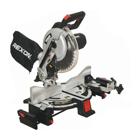
KNOW YOUR MITER SAW Safety Lock Carrying Handle Switch Handle Upper Blade Guard Motor Dust Bag Sliding Fence Laser Guide Bevel Lock Handle Extension Wing Lock Knob Hold Plate Table Stop Plate Clamp ON/OFF Tigger Switch Detent Lower Blade Detent Lock Knob Guard Head Down Lock Knob... -
Page 11: Assembly
ASSEMBLY 2. Push out the head lock down knob WARNING (2) into the locking hole (3). To avoid injury from unexpected IMPORTANT: To avoid damage, never starting or electrical shock, do not carry the miter saw by the switch plug the power cord into a source handle or the cutting arm. - Page 12 STORAGE Removing Blade (Fig. F, G, H) Storing the MiterMate™ Angle Finder 1. Unplug the saw from the outlet. (Fig. D) 2. Allow the cutting head to rise to the 1. Loosen the knob (1) on the upright position. Raise the lower MiterMate™...
- Page 13 8. Remove the arbor bolt (4), outer in while tightening the arbor bolt blade collar (6), and the blade (7). securely. (Fig. G) Do not remove the inner blade 5. Rotate the cover plate (3) back to its collar. (Fig. H) original position until the slot in the NOTE: Pay attention to the pieces cover plate engages with the cover...
-
Page 14: Mounting Instructions
● Never carry the miter saw by the NOTE: Mounting hardware is not power cord or by the switch handle. included with this tool. Bolts, nuts, Carrying the tool by the power washers, and screws must be cord could cause damage to the purchased separately. -
Page 15: Adjustments
ADJUSTMENTS Fig. L WARNING To avoid injury from an accidental start, make sure the switch is in the OFF position and the plug is not connected to the power source outlet. BEVEL STOP ADJUSTMENT (FIG. L, M, N) Fig.M WARNING NOTE: The upper blade guard has... - Page 16 45° Bevel Adjustment (Fig. O) To Adjust the Angle: 1. Unlock the bevel lock handle (1) 1. Unlock the left sliding fence unit and tilt the cutting arm as far to the by unlocking the positive stop lock left as possible. lever (1) behind the sliding fence 2.
- Page 17 ADJUSTING SLIDING FENCE UNITS Fig. R SQUARENESS AND ALIGNMENT (FIG. Q, R, S) 1. Lower the cutting arm and lock in position. 2. Using a square, lay the heel of the square against the worktable, and the rule against the blade. Check to see if the angle between the worktable and the blade is 90°.
- Page 18 ADJUSTING LOCK LEVERS (FIG. T) 5. Repeat until adjusted properly, and After a period of use, the lock levers tighten the locknut to secure the might loosen and couldn’t clamp the adjustment bolt into position. sliding fence units tightly. An adjustment is needed. Fig.
- Page 19 ● If you have any problem or question THE LASER GUIDE (FIG. W, X, Y) on the laser guide, please call the WARNING Service Center. For your own safety, never connect the plug to a power source outlet AVOID DIRECT EYE CONTACT until all the adjustment steps ...
- Page 20 ● Use of controls or adjustments B. Adjusting the Translation Position or performance of procedures of the Laser Beam (Fig. X, Y) other than those specified herein 1. Loosen two securing screws (3) may result in hazardous radiation slightly. (Fig. X) exposure.
-
Page 21: Operation
OPERATION ● Compare the direction of rotation SAFETY INSTRUCTIONS FOR BASIC SAW OPERATION arrow on the guard to the direction arrow on the blade. The blade teeth BEFORE USING THE MITER SAW should always point downward at the front of the saw. WARNING ●... - Page 22 ● Tighten the arbor bolt. SAFETY INSTRUCTIONS FOR BASIC ● Tighten the cover plate screw. SAW OPERATION ● Check for damaged parts. BEFORE USING THE MITER SAW Check for: WARNING ● Alignment of moving parts ● Damaged electric cords To avoid mistakes that could cause ●...
- Page 23 DRESS FOR SAFETY CAUTION Any power tool can throw To avoid burns or other fire damage, foreign objects into the eyes. never use the miter saw near This can result in permanent flammable liquids, vapors, or gases. eye damage. Everyday eyeglasses have only impact resistant ●...
- Page 24 ● Make sure there are no gaps WARNING between the workpiece, fence and To avoid injury, follow all applicable table that will let the workpiece shift safety instructions, when cutting after it is cut. non-ferrous metals: ● Keep the cut off piece free to move ●...
- Page 25 Starting a cut: BASIC SAW OPERATIONS ● Place hands at least 15.2 cm away WARNING from the path of the blade – out of the “no-hands zone” (1). For your convenience, your saw ● Hold workpiece firmly against the has a blade brake. The brake is fence to prevent movement toward not a safety device.
- Page 26 BEFORE LEAVING THE SAW 5. If the desired angle is not one of ● Never leave tool running positive stops, simply lock the unattended. Turn power OFF. Wait sliding fence unit by flipping the lock for all moving parts to stop and lever down.
- Page 27 BEVEL CUT (FIG. DD) 3. If the desired angle is one of the 1. When a bevel cut is required, positive stops, tighten the positive stop loosen the bevel lock handle for lock lever, and then flip the lock lever angle adjusting.
- Page 28 WORKPIECE SUPPORT AND Fig. HH REPETITIVE CUTTING USING THE STOP PLATE (FIG. FF) Long workpieces need to be supported by the extension wing. 1. Slide the extension wing to desired Inside Corner Outside Corner position and tighten the knob. 2. The stop plate (1) is designed for use during repetitive cutting.
- Page 29 4. Individually lock the left and right Fig. JJ Ceiling sliding fence units by flipping down the lock lever (6). 5. Remove the MiterMate™ angle 52° finder from the saw. Wall 6. Respectively place a base/crown molding piece against the left and right sliding fence units, and perform 38°...
- Page 30 Cutting base molding: CONVENTIONAL WAY OF CUTTING Base moldings and many other CROWN/BASE MOLDING moldings can be cut on your miter saw. The setup of the saw depends on The following instructions are not the molding characteristics and application. optimum way to cut molding using Perform practice cuts on scrap material the miter cutting feature.
- Page 31 Cutting crown molding Fig. NN (Fig. NN, OO): Your compound miter saw is suited for the difficult task of cutting crown Workpiece molding. To fit properly, crown molding must be cut with extreme accuracy. The two surfaces on a piece of crown Miter Saw Table molding that fit flat against the ceiling and wall are at angles that, when...
-
Page 32: Crown Molding Chart
CROWN MOLDING CHART MiterMate™ Miter Saw Miter and Bevel Angle Settings Wall to Crown Molding Angle 52/38° Crown Molding 45/45° Crown Molding 52/38° Crown Molding 45/45° Crown Molding Angle Angle Miter Bevel Miter Bevel Miter Bevel Between Miter Setting Bevel Setting Between Setting Setting... -
Page 33: Maintenance
MAINTENANCE MAINTENANCE NOTE: To reinstall the same brushes, first make sure the brushes go back in DANGER the way they came out. This will avoid To avoid injury, never put lubricants a break-in period that reduces motor on the blade while it is spinning. performance and increases wear. -
Page 34: Troubleshooting Guide
TROUBLESHOOTING GUIDE WARNING To avoid injury from accidental starting, always turn switch OFF and unplug the tool before moving, replacing the blade or making adjustments. TROUBLESHOOTING GUIDE - MOTOR PROBLEM PROBLEM CAUSE SUGGESTED CORRECTIVE ACTION Brake does 1. Motor brushes not sealed or 1. -
Page 35: Parts List
COMPOUND MITER SAW WARNING When servicing use only REXON replacement parts. Use of any other parts many create a HAZARD or cause product damage. Any attempt to repair or replace electrical parts on this Miter Saw may create a HAZARD unless repair is done by a qualified service technician. - Page 36 10 IN. (254 MM) MiterMate COMPOUND MITER SAW SCHEMATIC A...
- Page 37 10 IN. (254 MM) MiterMate COMPOUND MITER SAW PARTS LIST FOR SAW SCHEMATIC B I.D. Description Size Q’ty I.D. Description Size Q’ty 0824 PIVOT SHAFT 2VE6 BASE 0826 NEEDLE POINTER 2VE8 RIGHT-PIVOT-SUPPORT 0828 ROTATION SLIDE PLATE 2VE9 LEFT-PIVOT-SUPPORT 081U SUPPORT 2VEB RIGHT-FENCE 0D7W CLEVIS PIN...
- Page 38 10 IN. (254 MM) MiterMate COMPOUND MITER SAW SCHEMATIC B...
- Page 39 10 IN. (254 MM) MiterMate COMPOUND MITER SAW PARTS LIST AND SCHEMATIC FOR MOTOR I.D. Description Size Q’ty I.D. Description Size Q’ty 0QGR COMPRESSION SPRING 3236 CR. RE. PAN HD. SCREW & WASHER M6*1.0-55 0QR0 BRUSH COVER 3712 ARMATURE ASS’Y 32CA BRACKET STOP ASS’Y 37J5...
- Page 40 ®...
Need help?
Do you have a question about the M2507R and is the answer not in the manual?
Questions and answers