Table of Contents
Advertisement
Advertisement
Table of Contents

Subscribe to Our Youtube Channel
Related Manuals for REXON SM2158R


Summary of Contents for REXON SM2158R
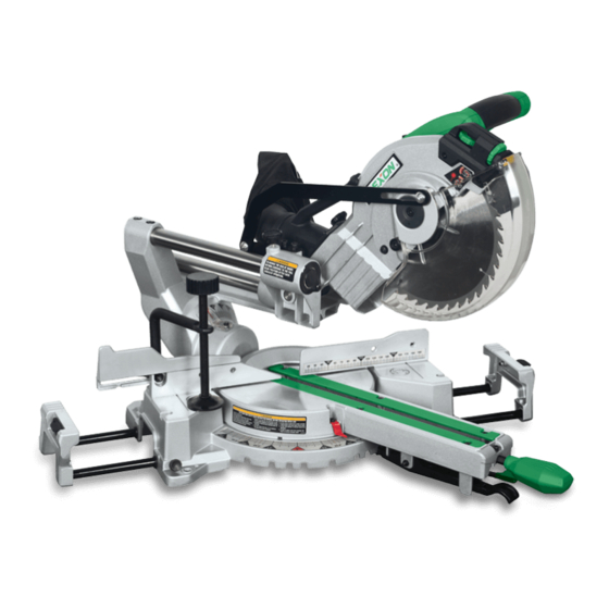
- Page 1 ® 8-1/2 in. (216 mm) SLIDE COMPOUND MITER SAW SM2158R INSTRUCTION MANUAL...
- Page 2 CONTENTS P 1 - 20...
-
Page 3: Carton Contents
CARTON CONTENTS UNPACKING 1. Carefully remove the miter saw from the carton. 2. Separate and layout all of the parts. Carefully check them according to the diagram below. IMPORTANT: Always use the designated carrying handle and hand-hold on the side of the saw base for transportation. WARNING! If any part is missing or damaged, do not plug in the miter saw until you have replaced the missing or damaged parts. -
Page 4: General Safety Rules
General Safety Rules working outdoors. Wear protective hair covering to contain long hair. WARNING ! When using electric tools 9. Use protective equipment. Use basic safety precautions should safety glasses. Use face or dust always be followed to reduce the risk mask if cutting operations create of fire, electric shock and personal dust. -
Page 5: Miter Saws
17. Avoid unintentional starting. equipment (e.g. blinking of a lamp). Ensure switch is in “off” position If the mains-impedance zmax < 0.34 when plugging in. Ohm, such disturbances are not 18. Use outdoor extension leads. expected. When the tool is used outdoors, use 24. - Page 6 9. The operator must be adequately 12. The laser fitted onto this miter saw trained in the operation of miter saws is only designed for this saw. The and their components. fitting of any external, additional 10. Wear suitable personal protective or different type of laser is not equipment when necessary, this permitted.
- Page 7 Wear safety goggles Installation Wear ear protection Wear a breathing mask KNOW YOUR MITER SAW (FIG. 1) 1. Laser horizontal adjustment knob Read and understand 2. Laser vertical adjustment knob instruction manual: to reduce 3. Lower blade guard the risk of injury, user and all 4.
- Page 8 TRANSPORTING THE SAW (FIG. 1) Specifications To avoid damage, never carry the miter saw by the switch handle, the cutting Motor ....400 W, S6: 20%, 10 min arm or the miter handle. ALWAYS use 220 V~, 60 Hz, Double Insulation the designated carrying handle (24).
- Page 9 INSTALLING THE MITER HANDLE NOTE: There are no screws to (FIG. 3) secure clamp. The clamp will secure 1. Insert the miter handle (1) into the itself to the base when turning the hole (2) in front of the miter saw and knob (3) to clamp the workpiece.
- Page 10 REMOVING AND INSTALLING THE Setting the Tool TABLE INSERT (FIG. 10) NOTE: This tool is accurately adjusted WARNING! before shipping from the factory. Check To avoid injury: the following accuracy and readjust ● Always unplug the saw to avoid them if necessary in order to obtain the accidental starting.
- Page 11 90° Bevel pointer adjustment Adjusting Miter Angles: (Fig. 12) 1. Lift up on the quick-cam locking 1. When the blade is exactly 90° lever (1) to unlock the table. (0°) to the table, loosen the bevel 2. Move the table while lifting up on pointer screw (6) using a # 2 Phillips the positive stop locking lever (2) to screwdriver.
- Page 12 ADJUSTING CUTTING DEPTH 3. Recheck the blade depth by moving (FIG. 16) the cutting head front to back The maximum depth travel of the through the full motion of a typical cutting head was set at the factory. cut along the control arm. NOTE: If the stop plate becomes Setting the maximum width travel of loose, it can interfere with raising...
- Page 13 ALIGNING THE LASER BEAM ● Do not attempt to repair or (FIG. 19, 20, 21, 22) disassemble the laser. If unqualified persons attempt to WARNING! For your own safety, repair this laser product, serious never connect the plug to power injury may result.
- Page 14 6. Looking at the front of the board, Connecting to the Power Supply if the laser line is not parallel to Check that the power supply and plug the “pattern line” please follow the used is in accordance with your miter instructions listed below under saw.
- Page 15 NOTE: Mounting hardware is not Mounting the Tool included with this tool. Bolts, nuts, washers and screws must be WARNING! TO AVOID INJURY FORM purchased separately. UNEXPECTED SAW MOVEMENT: 2. For portable use, place the saw on ● Disconnect the power cord from a 19.05 mm thick piece of plywood.
- Page 16 2. To cut wide boards up to 305 mm, TURNING SAW ON (FIG. 25) the slide carriage lock knob (1) Squeeze the trigger switch (1) to turn must be loosened to allow the the miter saw ON. Release the trigger cutting head to slide freely.
- Page 17 4. Once the desired miter angle is COMPOUND CUT (FIG. 30, 31) achieved, press down on the quick- A compound cut is the combination of cam locking lever (1) to secure the a miter and a bevel cut simultaneously. table into position. 1.
-
Page 18: Installing The Blade
Vertical Position Horizontal Position SETTINGS Left Side Right Side (Back of molding is (Back of molding is SETTINGS against the fence) flat on the table) Miter Angle 31.6 ° Right 31.6 ° Left Inside Corner 0 ° 45 ° Bevel Angle Bevel Angle 33.9 °... - Page 19 IMPORTANT: Make sure the flats of 4. While holding the lower blade guard, loosen the cover plate the blade collars are engaged with screw (2) with a Phillips screwdriver. the flats on the arbor shaft. Also, the 5. Rotate the cover plate (3) to expose flat side of the blade collar must be the arbor bolt (4).
- Page 20 Maintenance WARNING: For your own safety, turn the switch off and remove the plug from the power source outlet before maintaining or lubricating your miter saw. GENERAL MAINTENANCE Occasionally use a cloth to wipe off chips and dust from the machine. And oil the rotary parts once a month to extend the tool life.
- Page 21 FIG. 1 FIG. 2 FIG. 4 FIG. 3 FIG. 5...
- Page 22 FIG. 9 FIG. 6 FIG. 10 FIG. 7 FIG. 8 FIG. 11...
- Page 23 FIG. 12 FIG. 15 FIG. 16 FIG. 13 FIG. 14 FIG. 17...
- Page 24 Clockwise Counterclockwise Pattern line Laser line FIG. 18 FIG. 21 TOP VIEW Counterclockwise Clockwise Laser line Cutting Blade line Laser line Pattern line Workpiece Laser line Cutting line FIG. 19 FIG. 22 1. Miter saw base 2. Hex head bolt 3.
- Page 25 FIG. 27 No-Hand Zone 6-3/4 in. 6-3/4 in. FIG. 24 FIG. 28 FIG. 25 FIG. 29 FIG. 30 FIG. 26...
- Page 26 FIG. 31 FIG. 35 workpiece workpiece Miter saw table Miter saw table miter at 45°, bevel at 0° miter at 0°, bevel at 45° FIG. 32 FIG. 36 Workpiece Miter saw table FIG. 33 FIG. 37 Inside corner Outside corner Compound cut crown moldings FIG.
- Page 27 SM2158R PARTS LIST ORDER ONLY BY MODEL NUMBER AND PART NUMBER I.D. NO. DESCRIPTION SIZE Q’TY I.D. NO. DESCRIPTION SIZE Q’TY 082J CUSHION 0KDW CR. RE. PAN HD. SCREW M6*1.0-20 082L BOLT 0KL1 CR.RE. PAN HD. ROUND M6*1.0-12 082P SCREW STOP...
- Page 28 SM2158R SAW PARTS LIST ORDER ONLY BY MODEL NUMBER AND PART NUMBER I.D. NO. DESCRIPTION SIZE Q’TY I.D. NO. DESCRIPTION SIZE Q’TY 2YR6 SPRING GUARD 3H96 CUTTER SHAFT GUARD 31VX CR. RE. TRUSS HD. ROUND M6*1.0-14 3H98 SEGMENT HANDLE NECK SCREW...
- Page 29 Schematic MODEL: SM2158R...
- Page 30 SM2158R MOTOR PARTS LIST ORDER ONLY BY MODEL NUMBER AND PART NUMBER I.D. NO. DESCRIPTION SIZE Q’TY 0HV2 BALL BEARING 0HX7 NEEDLE ROLLER BEARING 0JCD SPRING PIN 0JX2 HEX. SOC SET SCREW M5*0.8-6 0K43 CR. RE. PAN HD. SCREW & WASHER M5*0.8-16...
- Page 31 NOTES...
- Page 32 ®...
Need help?
Do you have a question about the SM2158R and is the answer not in the manual?
Questions and answers