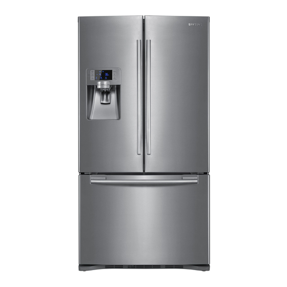
Samsung RFG237AA Service Manual
Bottom mount freezer
Hide thumbs
Also See for RFG237AA:
- User manual (92 pages) ,
- Specifications (2 pages) ,
- Manual de usuario (51 pages)
Table of Contents
Advertisement
Quick Links
RFG238AA
For the latest parts information, Please access to our service web site
(● North America : http://service.samsungportal.com)
REFRIGERATOR
BOTTOM MOUNT FREEZER
BASIC : RFG237AA / RFG238AA
MODEL NAME : RFG237AARS
RFG237AABP
RFG237AAWP
RFG237AAPN
MODEL CODE : RFG237AARS/XAA RFG238AARS/XAA
RFG237AABP/XAA RFG238AABP/XAA
RFG237AAWP/XAA RFG238AAWP/XAA
RFG237AAPN/XAA RFG238AAPN/XAA
CONTENTS
2. PRODUCT SPECIFICATIONS · · · · · · · · · · 8
4. TROUBLESHOOTING · · · · · · · · · · · · · · · · 52
5. EXPLODED VIEW & PARTS LIST · · · · 97
6. PCB DIAGRAM · · · · · · · · · · · · · · · · · · · · 120
7. WIRING DIAGRAM· · · · · · · · · · · · · · · · · · 126
8. SCHEMATIC DIAGRAM · · · · · · · · · · · · 127
RFG238AARS
RFG238AABP
RFG238AAWP
RFG238AAPN
Advertisement
Table of Contents


Need help?
Do you have a question about the RFG237AA and is the answer not in the manual?
Questions and answers