Table of Contents
Advertisement
Advertisement
Table of Contents

Related Manuals for Kidde Stratos-HSSD 2


Summary of Contents for Kidde Stratos-HSSD 2
- Page 1 High Sensitivity Smoke Detector Installer’s Handbook • LM80004 • Issue 12...
- Page 2 Reproduction of this document is strictly prohibited unless express written permission is obtained from Kidde Products Ltd. In line with continuous product improvement Kidde Products Ltd. reserves the right to modify or update specifications without notice. Stratos-HSSD, Stratos-Quadra, SenseNET, Stratos-Micra, FastLearn and ClassiFire are trademarks of Kidde Products Ltd.
-
Page 3: Introduction
0V or signal earth. Kidde Products Ltd. has taken every care to ensure that Stratos is as simple to install as possible but in case of difficulty, please contact our Help Line to ensure trouble free installation and operation. -
Page 4: Types Of Detector
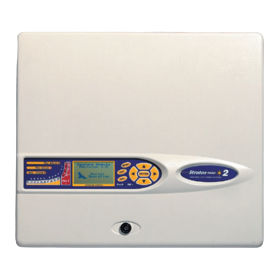
1. Types of Detector 1.1 Standard Detector The Standard Detector may be operated as a stand-alone unit, or may be part of a network of detectors centrally monitored by a Command Module (see section 1.2). It may be programmed via the front panel as in the version shown above. Alternatively, and for detectors ordered without front panel display, the detector may be pro- grammed remotely via the detector’s RS485 terminals using a Command Module, or via the detector’s RS232 port using a PC running... - Page 5 1.3 Standard Detector interior view Terminal block connections (see section 5.3.1) RS485 terminal connections (see section 5.3.1) 24VDC power supply connections (see section 5.4.1) 1A 5 x 20mm T-type protection fuse Detector address DIP switch (see section 8.1) Front panel display connector Filter removal tab (see section 10) RS232 serial port (see section 8.5) Safety earth studs (see section 5.4)
- Page 6 1.4 Stand-alone command module interior view Terminal block connections (see section 5.3.2) 24VDC power supply connections (see section 5.4.2) 500mA 5 x 20mm T-type protection fuse Internal power supply (see section 5.4.3) Stand-by batteries (see section 5.4.4) RS232 serial port Safety earth studs (see section 5.4) Front panel display connectors Display fixing screws (see section 5.2.1)
-
Page 7: Display Fixing Screws (See Section 5
1.5 Command module detector interior view Detector CPU board (see section 1.3) Command Module CPU board (see section 1.4) Command Module display connection Detector display connection Display fixing screws (see section 5.2.1) Page 7 Stratos HSSD-2 • INSTALLER’S HANDBOOK • Iss. 12... -
Page 8: Controls And Indicators
2. Controls and Indicators Standard Detector Command Module detector Aux, Pre-Alarm, Fire 1 and Fire 2 indicators illuminate when the appropriate alarm level has been reached and the appropriate time delays have expired. On a stand-alone Command Module, the indicators signify an alarm condition from any detector on the communications loop. - Page 9 TEST. When enabled, pressing <TEST> will start a lamp test and then the detector will show its nominal operating sensitivity as calculated by the ClassiFire Artificial Intelligence System. ISOL. Pressing <ISOL> will toggle the unit‘s isolation state. When isolated, the unit cannot generate any alarms and will signal a fault condition and the text display will show Panel Isolate.
-
Page 10: Programming The Unit
3. Programming The Stratos-HSSD-2 programmer means that programming and configuration of the the unit unit can be performed without opening the detector case. To enter programming mode, press any of the program menu keys 3.1 Engineering The Engineering Access code is required to allow the detector parameters to be Access code programmed. - Page 11 3.2 Main menu When the correct access code is entered, the display will show the main menu. The current selection is always shown with an arrow after it. Press to activate the selection. The choices available in the main menu are, in order: Setup menu : contains all the user-programmable functions Log menu : Allows the user to view historical information such as the event log (time and date of various events such as alarm or fault conditions)
-
Page 12: Stratos Hssd-2 • Installer's Handbook • Iss
3.3 Navigating through To navigate through the main menu options, press to navigate through the the menus available choices. The display shows two adjacent items, e.g. Setup menu Log menu Pressing Log menu Diagnostic menu would then show: Exit or pressing would show: Setup menu i.e.,... - Page 13 3.4 Stratos-HSSD-2 A list of all programmable functions follows with an explanation of their usage and the functions menu and submenu in which they can be found. The location of each sub-menu and function within the main menu is shown in the menu map (section 3.5). The menu map also shows the valid input range for programming parameters.
- Page 14 3.4.2 Alarm levels (Numeric - Address 001-127) > Setup menu Alarm levels The value set in the Pre Alarm level, Fire 1 level and Aux level functions in the Alarm levels submenu is the relatively scaled bargraph level at which the appropriate alarm is initiated on the detector.
- Page 15 If the detector is in FastLearn mode, setting this function to No will stop the FastLearn process. Using the function in this way is neither recommended nor supported by Kidde Products Ltd Setting this function to Yes will start a FastLearn at any time. The bargraph display on the front of the detector will show a rolling segment display on the front panel for the fifteen minutes that it takes to complete.
- Page 16 3.4.9 Auto FastLearn enable / disable (Yes/No - Address 001-127) Setup menu > Alarm levels As default, this function is set to Yes. This ensures that if the detector is powered down for any reason (e.g. for maintenance or to be moved to a new area), a FastLearn is commenced automatically on power-up.
- Page 17 3.4.13 Latching faults (Yes/No - Address 000-127) > Setup menu Alarm actions When this function is set to Yes it requires a reset from the front panel or a remote reset to clear fault indications. This is the factory default setting. It may be applied to the Command Module or a Standard Detector.
- Page 18 Thus, for example, the name of the area being protected, or the name of the person responsible for fire safety could be entered. The default device text is Stratos-HSSD 2 and the firmware revision level for the Standard Detector, and Command Module and the firmware revision level for the Command Module.
- Page 19 Setup menu Power checks The Stratos-HSSD 2 detector and Command Module are capable of signalling power supply faults from the power supply where this is equipped with a fault relay (the power supply fitted by default has this feature). The mains check is disabled by default.
- Page 20 3.4.31 Chart log recording rate (Numeric - Address 000-127) > Setup menu Miscellaneous This function controls how frequently the detector and alarm level or flow rates are stored in the Standard Detector or Command Module internal chart recorder log. The chart log recording rates are as follows. time per division setting type...
- Page 21 Wide Area Network. This function may then be set to a more suitable value. NB: If in doubt about the setting of this function, please contact the Kidde Products Ltd. help line (see page 3). Page 21...
- Page 22 3.4.38 Call centre (Numeric - CM only) > Setup menu Pager This is the phone number the modem dials up to send a message. For further details on this and the other functions in the “Pager” submenu, see section 6.1.3, “Paging from the Command Module”.
- Page 23 3.4.45 Detector read (Display - Address 001-127) Diagnostic menu This function displays five values as shown: 009.47% 086 091 087 091 The top value is the detector’s current smoke level reading as a percentage of the full-scale value, and the bottom four readings are the current flow rates on each pipe as a percentage of the maximum possible flow rate.
-
Page 24: Menu Map
3.5 Menu map Menu Submenu Item Para Time HH:MM Time and Date 3.4.1 Date DD/MM/YYYY Alarm levels Fire 2 level (1-25) Fire 1 level (8-10) 3.4.2 Pre Alarm level (3-8) Aux level (2-10) Fire 2 delay (0-99) Fire 1 delay (0-60) 3.4.3 Pre Alarm delay (0-60) Aux delay (0-60) - Page 25 4. Sampling Aspirating system design is inherently simple. It is often possible to achieve good Pipe Design system performance with very simple installations. There are however a few rules which must be adhered to, and these rules are equally applicable to all aspirating systems which operate on similar principles to Stratos-HSSD.
-
Page 26: Installation
Unused sampling pipe inlets must be closed. For advice on pipe layout design ■ consult the ‘System Manual’ and contact Kidde Products Ltd. help line (see page 3) in case of difficulty. The exhaust air from the unit must not be impeded in any way. If the unit is ■... - Page 27 5.2 Mechanical The detector body is fitted to a wall-mounting bracket which is attached to the wall via installation the mounting holes E as shown below. The detector is then fitted over the mounting stud D and secured inside the detector body with the nut provided for the purpose. For a more discreet layout, it is possible to allow the sampling pipes and cables to enter the detector from the rear (see illustrations below), with the sample pipes and connection cables channelled into the wall.
- Page 28 5.2.1 Removal and To remove the front cover, unlock it using the key provided (turn anticlockwise). The replacement of the bottom of the front cover may then be lifted away from the detector chassis until the detector front cover top of the cover disengages from the retaining rails at the top of the chassis. The cover may then be removed.
- Page 29 5.3 Electrical All electrical (power and signal) connections should be made to the green terminal installation block inside the detector. Power cables should be screened and of sufficient current car- rying capacity. Signal cable should be 120Ω screened twisted pair such as Belden 9841 24AWG.
- Page 30 5.3.2 All electrical (power and signal) connections should be made to the green terminal Command Module block inside the detector. Power cables should be screened and of sufficient current car- terminal block rying capacity. Signal cable should be 120Ω screened twisted pair such as Belden 9841 connections 24AWG.
- Page 31 5.3.3 Connecting For the system to meet full EMC compliance requirements, the following precautions power cables should be taken: Screened power cable should be used. ■ The earth wire of power cables should be connected to the detector EARTH ■ terminal, and this in turn connected to an earth stud on the detector chassis.
- Page 32 5.4 Power Supply The detector may be powered by any EN54-4 compliant monitored 24DC power supply of sufficient capacity. Connections 5.4.1 Detector power supply connections Safety earth* Safety earth* + 24V DC + 24V DC 5.4.2 Command Module power supply connections Safety earth* + 24V DC...
- Page 33 5.4.3 Command The Command Module may be fitted with an integral power supply and battery Module internal charger. The relevant connections are shown below, although these will normally be power supply made when the unit is manufactured. This diagram applies only to Command Modules fitted with an integral supply, although connections to alternative external power supplies will be similar.
- Page 34 5.4.4 Backup batteries The Stratos-HSSD 2 Command Module can be fitted with 2 x 12V, 7 Ah backup batteries to give up to 24 hours’ operation in the event of mains power failure. The integral battery charger can recharge the batteries to a minimum of 80% capacity within 24 hours of mains reconnection to comply with BS5839 and EN 54 part 4.
- Page 35 5.5 Demonstration In normal use, the detector remains in a reduced sensitivity mode for 24 hours whilst it gathers information about its environment. For purposes of demonstration, e.g. to verify Mode a new installation, this may be disabled by putting the detector into “Demonstration Mode”.
-
Page 36: External Communications
6.1 BMS protocols on the Stratos-HSSD 2 Command Module Communications The Command Module of the Stratos-HSSD 2 has a second RS232 port that can be used to send messages to a pager or compatible GSM phone using a modem or to ena- ble connection to a Building Management System (BMS). - Page 37 For further information on BACnet implementation, contact the Help Line. (see page 3) 6.1.3 Paging from the Command Module The Stratos-HSSD 2 Command Module has the facility to send text messages to alphanumeric pagers or SMS messages to some mobile phones.
-
Page 38: Event Log
6.1.4 Configuring the software No manual configuration of the modem is required as the command module config- ures the modem automatically on dialling. The command module has three entries used to send messages. They are described below with an example for a BT pager. The functions may be found in Setup menu ➔... -
Page 39: Interfacing
8. Interfacing Because of the flexible nature of the Stratos-HSSD-2 ® detector and the many possible configurations, there are many options for interfacing the detectors to the Fire Panel. These include many third party interfaces available from various manufacturers. Because of this, it is not possible to give a complete list of all interfacing methods but the following pages will give details of the most common methods that are likely to be used. - Page 40 8.1.1 Address table Addresses chosen for detectors do not have to be consecutive or in a given order so long as they are all different. ADDRESS Page 40 Stratos HSSD-2 • INSTALLER’S HANDBOOK • Iss. 12...
- Page 41 The RS485 A and B wires should be taken through a ferrite (supplied) with a single loop illustrated for the power wires in section 5.3.3. The total length of interconnecting cable between adjacent Stratos-HSSD 2 detectors in the loop should not exceed 1.2 kilometres.
-
Page 42: Terminal Block Connections (See Section 5
8.3 Connecting a When a Command Module is being used to manage one or more detectors (the Command Module maximum limit is 127) then a Addressable Protocol Interface Card (APIC) may be used to decode detector status information in the Command Module and relay to the the to an addressable Fire Panel via the Addressable Bus 1 and Bus 2 terminal block connections (see section Fire Panel... -
Page 43: Terminal Block Connections (See Section 5
8.4 Connecting a An APIC may be used to decode detector status information and relay this the the Fire single Stratos-HSSD-2 Panel via the Addressable Bus 1 and Bus 2 terminal block connections (see section 5.3.1 to an addressable Fire ‘Detector terminal block connections’). -
Page 44: Commissioning
When multiple detectors are networked together and a Command Module is being used, the PC connects to the Command Module‘s 9-way RS232 port. The cable connections are the same as the Standard Detector cable connections. 9. Commissioning Before commissioning the detector the local standards of aspirating detection systems must be consulted. -
Page 45: Maintenance
9.1 Commissioning The following brief checklist allows quick setup of the detector. This procedure will be checklist adequate for most standard installations. Before powering up the detector, visually check all cabling to ensure correct connection. If wire identification is not immediately clear (e.g. by use of different coloured wires or wire identification sleeves) an electrical check should be made. - Page 46 As dust contained in the dust separators may expose maintenance personnel to a ‘Nuisance Dust‘ hazard as defined by the ‘Control of Substances Hazardous to Health‘ (COSHH), it is strongly recommended that suitable masks and protective clothing be worn when changing filters. Used separators are not intended for re-use and should be disposed of.
-
Page 47: Troubleshooting
11. Troubleshooting 11.1 Pressing RESET or ISOL. button has no effect • Check that the controls have been enabled. These functions are disabled by default. See section 3.4.24 11.2 Nuisance alarms occur too often Check that the ClassiFire alarm factor setting is appropriate for the normal working •... - Page 48 11.6 Flow fault errors • These occur when the airflow rate into the detector exceeds the pre-programmed parameters. As the detector ‘learns‘ the flow setup from the initial installation, this usually means that there has been some change in conditions. A Flow high fault may indicate that a sampling pipe is damaged, and a Flow low fault may indicate that the pipe has been blocked, e.g.
-
Page 49: Error Messages
PC and note the detector signal level at the time of the fault. When as much information as possible has been determined about the conditions at the time of the error, please contact the Kidde Products Ltd help line (see page 3). Page 49 Stratos HSSD-2 • INSTALLER’S HANDBOOK • Iss. 12... -
Page 50: Do's And Don'ts
13. Do’s and Don’ts Ensure that the ClassiFire alarm factor is appropriately set. ✔ Ensure that power and signal cables are correctly connected before powering up ✔ by use of cable identifiers or electrical continuity checks. Incorrect connection could damage the detector. Ensure that cable of an appropriate approved type is used for interconnection. -
Page 51: Stratos-Hssd-2 Specification
14. Stratos-HSSD-2 SELV rating (EN 60950) Class III specification Supply Voltage 21.6V - 26.4V DC PSU Type: conforming to EN 54-4 Electrical safety complies with IEC 61010-1 Size (mm) 427W x 372H x 95D ☞ This equipment is Weight 5.2kg (Detector) 5.3kg (Command only to be used in Module Detector) 6.2kg (Stand-alone Command Module) 10.1kg (Stand-alone... - Page 52 Kidde Products Limited • Unit 2 Blair Way Dawdon • City: Seaham, County Durham, SR7 7PP United Kingdom Tel: +44(0)191-513 6100 Fax: +44(0)191-513 6102...
Need help?
Do you have a question about the Stratos-HSSD 2 and is the answer not in the manual?
Questions and answers